

Page 1
No.PS##-OMH0006-C
PRODUCT NAME
Multi Channel Pressure Sensor Controller
MODEL / Series / Product Number
PSE200
Page 2

-1-
No.PS##-OMH0006-C
Table of Contents
Safety Instructions 2
Model Indication and how to order 8
Summary of Product parts 9
Definition and terminology 10
Mounting and Installation 13
Installation 13
Wiring 15
Internal circuit and wiring example 17
Setting of Function 18
Pressure Setting 22
Setting of Special Function 24
Other Settings 27
Maintenance 28
Troubleshooting 29
Specification 36
Specifications 36
Dimensions 37
Page 3
-2-
No.PS##-OMH0006-C
Safety Instructions
These safety instructions are intended to prevent hazardous situations and/or equipment damage.
These instructions indicate the level of potential hazard with the labels of "Caution", "Warning" or
"Danger". They are all important notes for safety and must be followed in addition to International
standards (ISO/IEC)
*1)
and other safety regulations.
*1) ISO 4414: Pneumatic fluid power -- General rules relating to systems
ISO 4413: Hydraulic fluid power -- General rules relating to systems
IEC 60204-1: Safety of machinery -- Electrical equipment of machines (Part 1: General requirements)
ISO 10218-1: Manipulating industrial robots -Safety.
etc.
Caution :
CAUTION indicates a hazard with a low level of risk which, if not avoided,
could result in minor or moderate injury.
Warning :
WARNING indicates a hazard with a medium level of risk which, if not
avoided, could result in death or serious injury.
Danger :
DANGER indicates a hazard with a high level of risk which, if not avoided,
will result in death or serious injury.
Warning
1. The compatibility of the product is the responsibility of the person who designs the
equipment or decides its specifications.
Since the product specified here is used under various operating conditions, its compatibility with specific
equipment must be decided by the person who designs the equipment or decides its specifications based on
necessary analysis and test results. The expected performance and safety assurance of the equipment will be
the responsibility of the person who has determined its compatibility with the product. This person should also
continuously review all specifications of the product referring to its latest catalog information, with a view to giving
due consideration to any possibility of equipment failure when configuring the equipment.
2. Only personnel with appropriate training should operate machinery and equipment.
The product specified here may become unsafe if handled incorrectly. The assembly, operation and
maintenance of machines or equipment including our products must be performed by an operator who is
appropriately trained and experienced.
3. Do not service or attempt to remove product and machinery/equipment until safety is confirmed.
1. The inspection and maintenance of machinery/equipment should only be performed after measures to prevent
falling or runaway of the driven objects have been confirmed.
2. When the product is to be removed, confirm that the safety measures as mentioned above are implemented
and the power from any appropriate source is cut, and read and understand the specific product precautions of
all relevant products carefully.
3. Before machinery/equipment is restarted, take measures to prevent unexpected operation and malfunction.
4. Contact SMC beforehand and take special consideration of safety measures if the product is
to be used in any of the following conditions.
1. Conditions and environments outside of the given specifications, or use outdoors or in a place exposed to direct
sunlight.
2. Installation on equipment in conjunction with atomic energy, railways, air navigation, space, shipping, vehicles,
military, medical treatment, combustion and recreation, or equipment in contact with food and beverages,
emergency stop circuits, clutch and brake circuits in press applications, safety equipment or other applications
unsuitable for the standard specifications described in the product catalog.
3. An application which could have negative effects on people, property, or animals requiring special safety
analysis.
4. Use in an interlock circuit, which requires the provision of double interlock for possible failure by using a
mechanical protective function, and periodical checks to confirm proper operation.
Page 4
-3-
No.PS##-OMH0006-C
Caution
The product is provided for use in manufacturing industries.
The product herein described is basically provided for peaceful use in manufacturing industries.
If considering using the product in other industries, consult SMC beforehand and exchange specifications or
a contract if necessary.
If anything is unclear, contact your nearest sales branch.
Limited warranty and Disclaimer/Compliance Requirements
The product used is subject to the following "Limited warranty and Disclaimer" and "Compliance
Requirements".
Read and accept them before using the product.
Limited warranty and Disclaimer
1. The warranty period of the product is 1 year in service or 1.5 years after the product is delivered.
∗2)
Also, the product may have specified durability, running distance or replacement parts. Please
consult your nearest sales branch.
2. For any failure or damage reported within the warranty period which is clearly our responsibility, a
replacement product or necessary parts will be provided.
This limited warranty applies only to our product independently, and not to any other damage
incurred due to the failure of the product.
3. Prior to using SMC products, please read and understand the warranty terms and disclaimers noted
in the specified catalog for the particular products.
∗2) Vacuum pads are excluded from this 1 year warranty.
A vacuum pad is a consumable part, so it is warranted for a year after it is delivered.
Also, even within the warranty period, the wear of a product due to the use of the vacuum pad or failure due to
the deterioration of rubber material are not covered by the limited warranty.
Compliance Requirements
1. The use of SMC products with production equipment for the manufacture of weapons of mass
destruction (WMD) or any other weapon is strictly prohibited.
2. The exports of SMC products or technology from one country to another are governed by the
relevant security laws and regulation of the countries involved in the transaction. Prior to the
shipment of a SMC product to another country, assure that all local rules governing that export are
known and followed.
Page 5
-4-
No.PS##-OMH0006-C
Operator
♦This operation manual is intended for those who have knowledge of machinery using pneumatic
equipment, and have sufficient knowledge of assembly, operation and maintenance of such
equipment. Only those persons are allowed to perform assembly, operation and maintenance.
♦Read and understand this operation manual carefully before assembling, operating or providing
maintenance to the product.
■Safety Instructions
Warning
■Do not disassemble, modify (including changing the printed circuit board) or repair.
An injury or failure can result.
■Do not operate the product outside of the specifications.
Do not use for flammable or harmful fluids.
Fire, malfunction, or damage to the product can result.
Verify the specifications before use.
■Do not operate in an atmosphere containing flammable or explosive gases.
Fire or an explosion can result.
This product is not designed to be explosion proof.
■Do not use the product in a place where static electricity is a problem.
Otherwise it can cause failure or malfunction of the system.
■If using the product in an interlocking circuit:
•Provide a double interlocking system, for example a mechanical system
•Check the product regularly for proper operation
Otherwise malfunction can result, causing an accident.
■The following instructions must be followed during maintenance:
•Turn off the power supply
•Stop the air supply, exhaust the residual pressure and verify that the air is released before performing
maintenance
Otherwise an injury can result.
Caution
■Do not touch the terminals and connectors while the power is on.
Otherwise electric shock, malfunction or damage to the product can result.
■After maintenance is complete, perform appropriate functional inspections and leak tests.
Stop operation if the equipment does not function properly or there is a leakage of fluid.
When leakage occurred from other parts except piping, the product might break.
Cut off power supply and stop supplying fluid.
Do not apply fluid at leaking condition.
Safety cannot be assured in the case of unexpected malfunction.
Page 6

-5-
No.PS##-OMH0006-C
■NOTE
○Follow the instructions given below when designing, selecting and handling the product.
●The instructions on design and selection (installation, wiring, environment, adjustment,
operation, maintenance, etc.) described below must also be followed.
∗Product specifications
•Use the specified voltage.
Otherwise failure or malfunction can result.
•Do not exceed the specified maximum allowable load.
Otherwise it can cause damage or shorten the lifetime of the Controller.
•Design the product to prevent reverse current when the circuit is opened or the product is forced to operate for
operational check.
Reverse current can cause malfunction or damage to the product.
•Input data to the Controller is not deleted, even if the power supply is cut off.
(Writing time: 100,000 times, Data duration: 10 years after power off.)
•Reserve a space for maintenance.
Allow sufficient space for maintenance when designing the system.
●Product handling
∗Installation
•Tighten to the specified tightening torque.
If the tightening torque is exceeded the mounting screws and brackets may be broken.
If the tightening torque is insufficient, the product can be displaced and loosen the mounting screws.
(Refer to "Mounting and Installation" on page 13.)
•Do not apply excessive stress to the product when it is mounted with a panel mount.
Otherwise damage to the product and disconnection from the panel mount can result.
•Be sure to ground terminal FG when using a commercially available switch-mode power supply.
•Do not drop, hit or apply shock to the Controller.
Otherwise damage to the internal parts can result, causing malfunction.
•Do not pull the lead wire forcefully, not lift the product by pulling the lead wire.
Power and output lead wire: 50N or less
Lead wire with connector for sensor: 25N or less
Hold the body when handling to avoid the damage of the Controller which lead to cause the failure and malfunction.
•Do not insert metal wires or other foreign matter into the pressure measurement port.
It can damage the pressure sensor causing failure or malfunction.
•Never mount a product in a location that will be used as a foothold.
The product may be damaged if excessive force is applied by stepping or climbing onto it.
∗Wiring
•Do not pull the lead wires.
In particular, never lift a Controller equipped with fitting and piping by holding the lead wires.
Otherwise damage to the internal parts can result, causing malfunction or to be off the connector.
•Avoid repeatedly bending or stretching the lead wire, or placing heavy load on them.
Repetitive bending stress or tensile stress can cause the sheath of the wire to peel off, or breakage of the wire.
If the lead wire can move, fix it near the body of the product.
The recommended bend radius of the lead wire is 6 times the outside diameter of the sheath, or 33 times the
outside diameter of the insulation material, whichever is larger.
Replace the damaged lead wire with a new one.
•Wire correctly.
Incorrect wiring can break the Controller.
•Do not perform wiring while the power is on.
Otherwise damage to the internal parts can result, causing malfunction.
Page 7

-6-
No.PS##-OMH0006-C
•Do not route wires and cables together with power or high voltage cables.
Otherwise the product can malfunction due to interference of noise and surge voltage from power and high voltage
cables to the signal line. Route the wires (piping) of the product separately from power or high voltage cables.
•Confirm proper insulation of wiring.
Poor insulation (interference from another circuit, poor insulation between terminals, etc.) can lead to excess
voltage or current being applied to the product, causing damage.
•Design the system to prevent reverse current when the product is forced to operate for operational
check.
Depending on the circuit used, insulation may not be maintained when operation is forced, allowing reverse current
to flow, which can cause malfunction and damage the product.
•Keep wiring as short as possible to prevent interference from electromagnetic noise and surge voltage.
Do not use a cable longer than 10 m.
Wire the DC(-) line(blue) as close as possible to the power supply.
∗Environment
•Do not use the product in area that is exposed to corrosive gases, chemicals, sea water, water or
steam.
Otherwise failure or malfunction can result.
•Do not use in a place where the product could be splashed by oil or chemicals.
If the product is to be used in an environment containing oils or chemicals such as coolant or cleaning solvent,
even for a short time, it may be adversely affected (damage, malfunction, or hardening of the lead wires)
•Do not use in an area where surges are generated.
If there is equipment which generates a large amount of surge (solenoid type lifter, high frequency induction
furnace, motor, etc.) close to the Controller, this may cause deterioration or breakage of the internal circuit of the
Pressure switch. Avoid sources of surge generation and crossed lines.
•Do not use a load which generates surge voltage.
When a surge-generating load such as a relay or solenoid is driven directly, use a Pressure switch with a built-in
surge absorbing element.
•The product is CE marked, but not immune to lightning strikes. Take measures against lightning strikes
in the system.
•Mount the product in a place that is not exposed to vibration or impact.
Otherwise failure or malfunction can result.
•Prevent foreign matter such as remnant of wires from entering the pressure switch.
Take proper measures for the remnant not to enter the Controller in order to prevent failure or malfunction.
•Do not use the product in an environment that is exposed to temperature cycle.
Heat cycles other than ordinary changes in temperature can adversely affect the inside of the product.
•Do not expose the product to direct sunlight.
If using in a location directly exposed to sunlight, shade the product from the sunlight.
Otherwise failure or malfunction can result.
•Keep within the ambient temperatures
The fluid and ambient temperatures is 0 to 50 oC.
Avoid sudden temperature change even within specified temperature.
•Do not operate close to a heat source, or in a location exposed to radiant heat.
Otherwise malfunction can result.
∗Adjustment and Operation
•Turn the power on after connecting a load.
Otherwise it can cause excess current causing instantaneous breakage of the Controller.
•Do not short-circuit the load.
Although error is displayed when the Controller load is short circuit, generated excess current lead to cause the
damage of the Controller.
•Do not press the setting buttons with a sharp pointed object.
It may damage the setting buttons.
Page 8

-7-
No.PS##-OMH0006-C
•If using the product to detect very small pressure rates, warm up the product for 20 to 30 minutes first.
There will be a drift on the display of approximate 1% immediately after the power supply is turned on.
•Perform settings suitable for the operating conditions.
Incorrect setting can cause operation failure.
For details of each setting, refer to page 18 to 27 of this manual.
•Do not touch the LCD during operation.
The display can vary due to static electricity.
∗Maintenance
•Turn off the power supply, stop the supplied air, exhaust the residual pressure and verify the release of
air before performing maintenance.
There is a risk of unexpected malfunction.
•Perform regular maintenance and inspections.
There is a risk of unexpected malfunction.
•Perform drainage regularly.
If condensate enters the secondary side, it can cause operating failure of pneumatic equipment.
•Do not use solvents such as benzene, thinner etc. to clean the Controller.
They could damage the surface of the body and erase the markings on the body.
Use a soft cloth to remove stains. For heavy stains, use a cloth soaked with diluted neutral detergent and fully
squeezed, then wipe up the stains again with a dry cloth.
Page 9
-8-
No.PS##-OMH0006-C
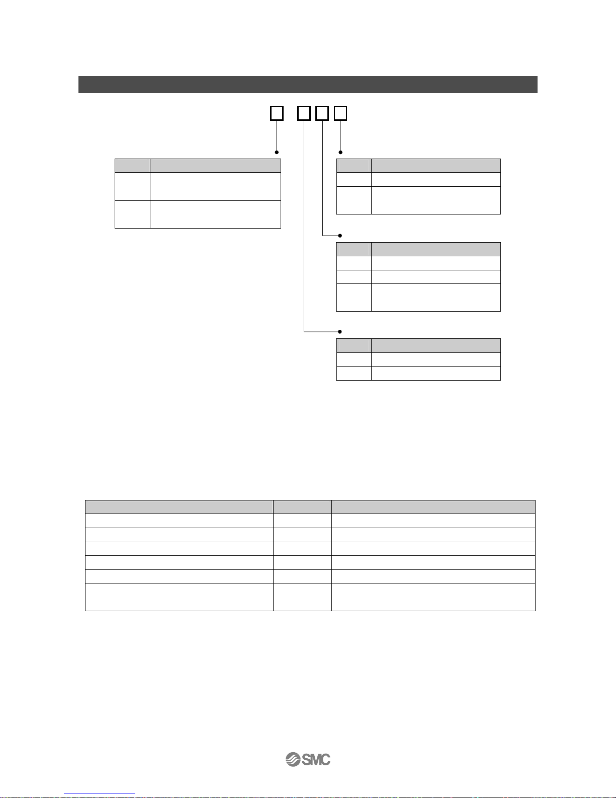
Model Indication and how to order
PSE20
-
Input/Output Specifications Option 2
Model Contents Model Contents
Nil No option
0
NPN open collector 5 outputs
+ Auto-shift Input
4C
Connector for sensor lead wire
(4 pcs.)
1
PNP open collector 5 outputs
+ Auto-shift Input
Option 1
Model Contents
Nil No option
A Panel mount adapter
B
Panel mount adapter
+ Front protective cover
Unit Specifications
Model Contents
Nil With unit conversion function
∗
1
M Fixed SI unit
∗
2
∗1: The new Measurement Law prohibits the
use of pressure switch with the unit
conversion function in Japan.
A unit label is attached.
∗2: Fixed unit
for compound, vacuum, low pressure: kPa
for positive pressure: MPa
○Option/Part number
Description Part number Note
Power and output lead wire ZS-26-A Length 2 m
Connector for sensor lead wire ZS-28-C 1 pc.
Panel mount adapter ZS-26-B With set screw M3x8 L (2 pcs.) and waterproof seal
Panel mount adapter + Front protective cover ZS-26-C With set screw M3x8 L (2 pcs.) and waterproof seal
Front protective cover ZS-26-01 -
□48 conversion adapter ZS-26-D
It is an adapter for attaching PSE200 series in the
panel cut size of PSE100 series.
Page 10
-9-
No.PS##-OMH0006-C
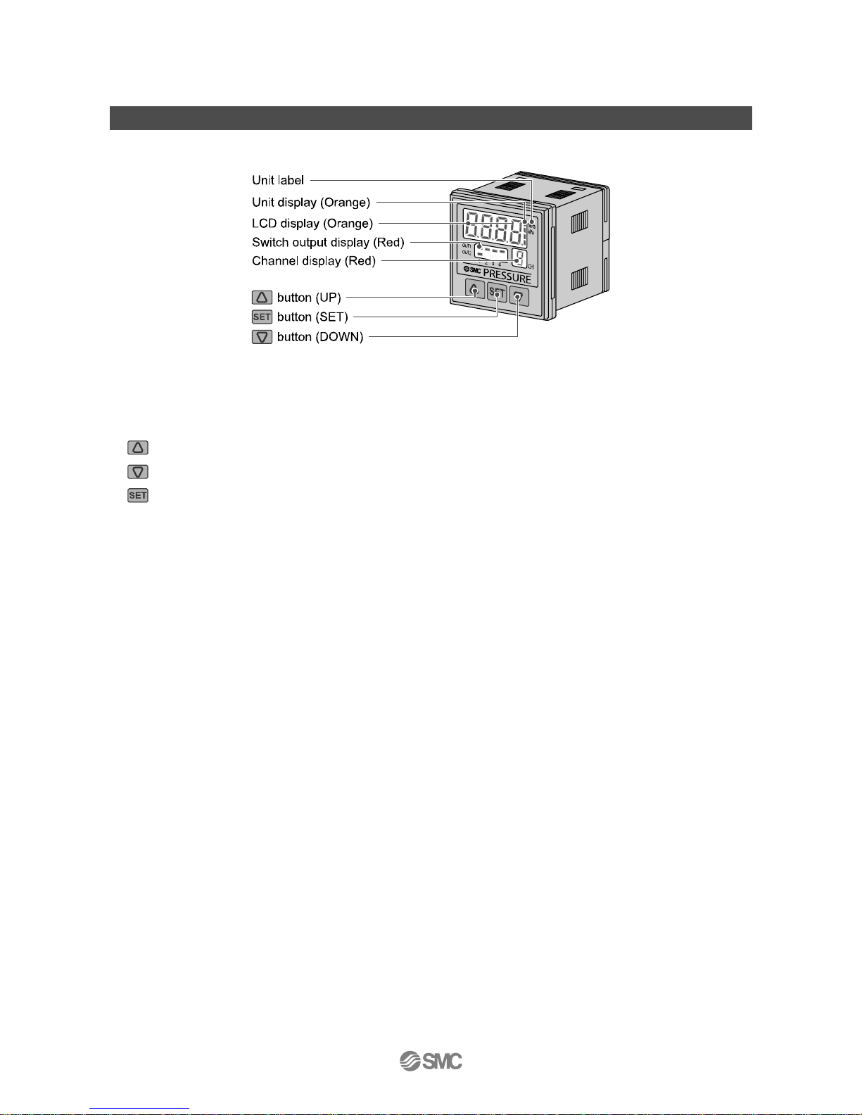
Summary of Product parts
○Names of individual parts
Switch output display (Red): Lit when OUT1 (CH1 to CH4) and/or OUT2 (only CH1) is ON.
LCD display (Orange): Displays the current status of pressure, setting mode, selected indication unit and
error code.
button (UP): Selects a mode and increases a set ON/OFF value.
button (DOWN): Selects a mode and decreases a set ON/OFF value.
button (SET): Changes the mode and sets a set value.
Unit display (Orange): Lit ON the indicator of selected unit. For the Controller without unit selection function,
the unit is fixed to SI (MPa or kPa).
Unit label: Attach the unit label (kgf/cm
2
, bar, psi, inHg, mmHg) with a unit selection function.
Channel display (Red): Indicate the CH1 to CH4 that is selected at that time.
Page 11
-10-
No.PS##-OMH0006-C
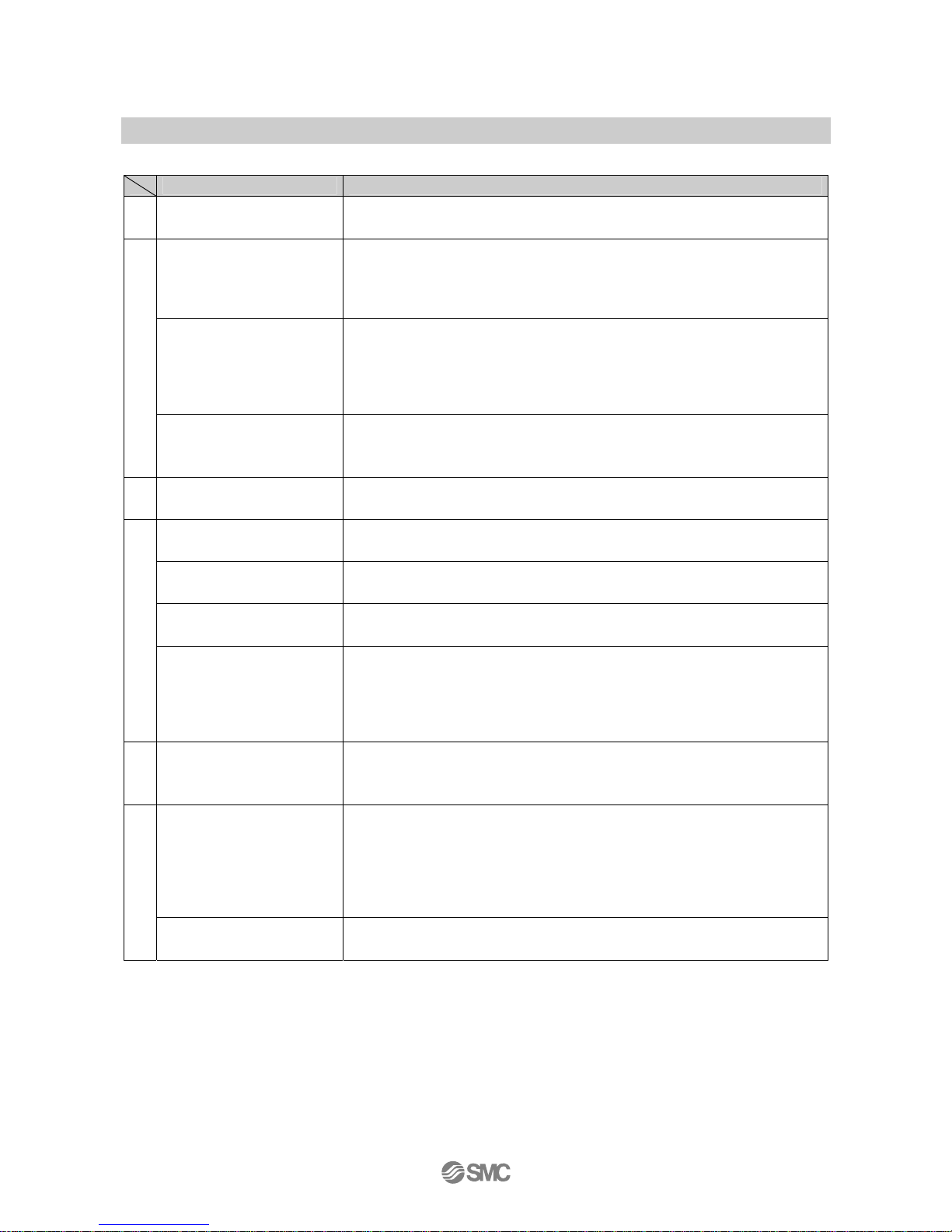
■Definition and terminology
Terms Meaning
7
7-segment indication
When "8" is shown on the display. It is called 7-segment because 8 consists of 7
pieces of "- (segments)".
Auto preset
A function of the Pressure switch to automatically setup pressure just by having
equipment hold and release a workpiece via vacuum adsorption. This function is
used in an application where vacuum adsorption of a workpiece needs to be
confirmed with a Pressure switch.
Auto shift
A function to correct the set value of the switch output in accordance with the
applied pressure in case the switch operation is unstable due to pulsation of
applied pressure. This function is used in applications such as vacuum
adsorption. The pressure when a signal is externally input is set as a reference
value with which the pressure that turns the switch on or off can be shifted.
A
Automatic identification
function
This function is enabled only when all connected sensors are PSE530 series.
(If just one is a different sensor, malfunction can result.)
The pressure range of the connected sensor is automatically identified and set.
B
Bottom value indication
(mode)
Shows the minimum pressure reached at that moment.
Channel scan (function)
The function to display the displayed values from CH1 to CH4 in order every two
seconds.
Chattering
The phenomenon caused in the switch output type in which the output turns on
and off repeatedly at high frequency.
Chattering-preventing
function
A function to delay the response time of switch output in order to prevent
chattering.
C
Copy between channels
The function to copy the settings of any channel (pressure and other initial setting
items) to other channels.
If the copy is performed from a one output channel (= CH2, CH3 and CH4) to a two
output channel (= CH1), it will not be applied to the setting of the second output of
the two output channel.
D
Digit (Min. setting unit)
Shows how precisely the pressure can be indicated or set by the digital Pressure
switch. When 1 digit = 1 kPa, the pressure is given with an increment of 1 kPa,
e.g., 1, 2, 3, …, 99, 100.
Direct output
One of the switch output types, and means the operation in which a switch is
turned on when pressure equal to the switch output set value or less is detected.
In the (hysteresis mode) window comparator mode, it indicates the operation in
which a switch is turned on when pressure outside the switch output range (n1L to
n1H or n2L to n2H) is detected.
(Refer to "List of output mode" on page 20.)
E
Error indication
With the self-diagnosis function given to the Pressure switch, it indicates that
there is a failure which could cause a switch failure.
Page 12
-11-
No.PS##-OMH0006-C
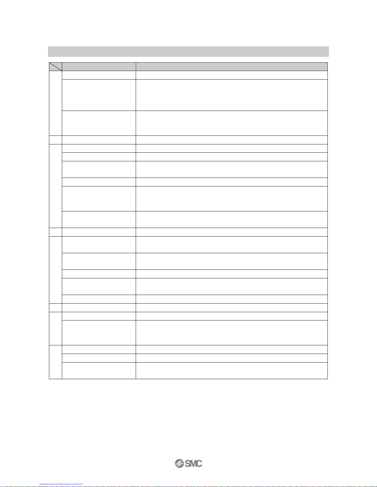
Terms Meaning
Fine adjustment mode Refer to "Fine adjustment of indicated value".
Fine adjustment of indicated
value (function)
An indicated pressure value can be adjusted within the range of ±5% R.D.
(±5% of the indicated value). It is used if a true pressure value is known or to
correct the difference of an indicated value of the measurement equipment
nearby that measures the same pressure as the Pressure switch.
F
F. S.
(full span/full scale)
Abbreviation for full span and full scale; means the maximum fluctuation range of
the Pressure switch rated value. For example, when the output voltage is 1 to
5[V], the F.S. will be 5-1 = 4[V]. (Reference: 1%F.S. = 4 × 0.01 = 0.04[V])
H Hysteresis Difference between the points at which the Pressure switch is turned on and off.
Indication accuracy Shows the deviation between displayed pressure value and the true pressure.
Indication light The light that turns on when the switch output is on.
Indication resolution
How fine the rated pressure range can be segmented. (Example: If a product for 0
to 1 MPa can indicate pressure by 0.001 MPa, the indication resolution is 1/1000.)
Indication unit The unit of pressure used in the display.
Initial setting (mode)
The mode to set the items other than pressure.
Pressure range, display color, operation mode, output format, response time and
auto-preset can be set.
I
Insulation resistance
Insulation resistance of a product itself. The resistance between an electric circuit
and a body.
K Key lock (function) Prohibits a change in the setting of the Pressure switch (locks button operation).
Manual setup
Manual pressure setup without using auto preset. This term is used to
discriminate from the pressure setup using auto preset.
Max. applied voltage
The maximum value of applied voltage available to the output line of the NPN
output.
Max. load current The maximum current available to the output (output line) of the switch output.
Measurement mode
The condition in which the pressure is being detected and indicated and switch
operation is enabled.
M
Min. setting unit Refer to "digit".
N
NPN (open collector) (output) The switch that uses the NPN transistor for output.
Operating mode There are two choices, hysteresis mode and window comparator mode.
O
Output style
The operation theory of the switch output. Either normal output or reversed output
can be selected.
Refer to "List of output mode" on page 20 for the operation status.
Peak value indication (mode) Shows the maximum pressure reached at that moment.
PNP (open collector) (output) The switch that uses the PNP transistor for output.
P
Pressure setting
The setting of pressure to determine the point at which the Pressure switch turns
on and off.
Page 13

-12-
No.PS##-OMH0006-C
Terms Meaning
Rated pressure range
The pressure range in which the Pressure switch satisfies the specifications.
Values over this range can be set if they are within the set pressure range, but
cannot assured the specifications to be satisfied.
R.D.
The value currently displayed.
For example, when the displayed value is 1.000, ±5%R.D. will be ±0.05, which is
±5% of 1.000, while for a displayed value of 0.800 it will be 0.04.
Repeatability
Reproducibility of the displayed value for pressure and ON-OFF output operating
point when the pressure changes at a temperature of 25
o
C.
Residual voltage
The difference between the ideal ON voltage and the actual voltage when the
switch output is on. It depends on present load current and ideally should be "0".
Resolution Refer to "Indication resolution".
Response time
The elapsed time until the ON-OFF output begins working since the pressure
supplied for the Pressure switch has reached the set value. Generally, the shorter
response time is, the better the performance is.
Reversed output
One of the switch output types, and means the operation in which a switch is
turned on when pressure equal to the switch output set value or less is detected.
In the (hysteresis mode) window comparator mode, it indicates the operation in
which a switch is turned on when pressure outside the switch output range (n1L to
n1H or n2L to n2H) is detected.
(Refer to "List of output mode" on page 20.)
R
Ripple A type of chattering.
Sampling cycle
The frequency in which the detected pressure should be reflected to the digital
indication.
Sensor input The part to which the output of the separate sensing part is connected.
Setting of function Refer to “initial setting (mode)”.
Setting pressure range The pressure range within which switch output can be set.
Special setting
Sets items other than pressure and initial setting items.
Sets the displayed value fine adjustment, copying between channels, auto-shift
and automatic identification function.
S
Switch output Alternatively called "ON-OFF output".
U
Unit conversion function
Function to change the unit in which the value of pressure is indicated. Only a
product with this function can change the unit. A product with unit-changing
function cannot be purchased if it is used within Japan. Pressure is indicated only
by SI units in Japan.
Window comparator mode
An output type that holds the output when the pressure is within a certain range.
(Refer to "List of output mode" on page 20.)
W
Withstand voltage
Durability to voltage applied between an electric circuit and a body. A product's
durability in withstanding voltage. If more voltage is applied to the product, the
product may be broken. (Voltage mentioned here is not power voltage to activate
the product.)
Z Zero clear (function) Adjusts the displayed pressure value to "0".
Page 14
-13-
No.PS##-OMH0006-C
Mounting and Installation
■Installation
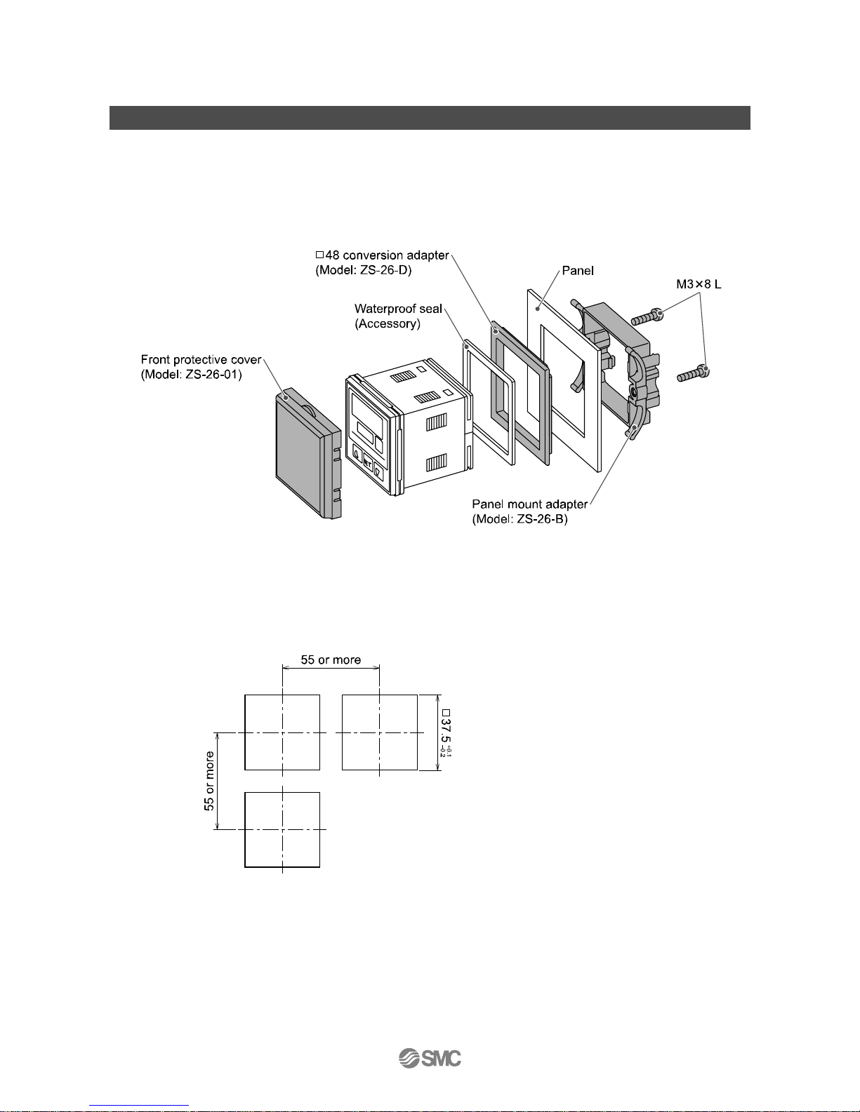
○Mounting by panel mount adapter
●Fix the panel mount adapter to the Controller with the set screws M3×8 L (2 pcs.) as attached.
•Panel mount adapter (Model: ZS-26-B)
Panel mount adapter + Front protective cover (Model: ZS-26-01)
□48 conversion adapter (Model: ZS-26-D)
∗: The panel mount adapter can be rotated by 90 degrees for mounting.
∗: Front panel of this Controller meets IP65 (if □48 conversion adapter is used, it meets IP40). However, if the panel mount adapter
is hold enough with screw and the instrument is not seated correctly, water might enter. Screw shall be tightened 1/4 to 1/2 turns
more after touched correctly.
○Panel cutout dimension
∗: Panel thickness 0.5 to 8 mm
Page 15
-14-
No.PS##-OMH0006-C
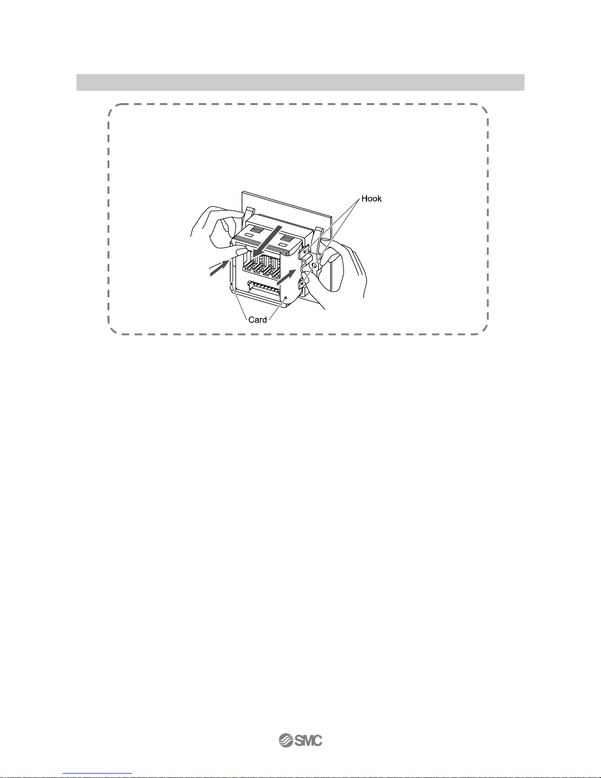
Notice when removing to the controller
●The Controller with the panel mount adapter can be removed from facility after
removing two screws as shown in a figure, by making insert the suitable thin card for
the hook of both the sides, pull a panel mount adapter to the front, and remove it.
If panel mount adapter is drawn forward with hook caught, the adapter and
Controller may be damaged.
Page 16
-15-
No.PS##-OMH0006-C
■Wiring
○Connection
•Connections should only be made with the power supply turned off.
•Use separate routes for the Multi Channel Pressure Sensor Controller wiring and any power or high
voltage wiring. Otherwise, malfunction may result due to noise.
•Ensure that the FG terminal is connected to ground when using a commercially available switch-mode
power supply.
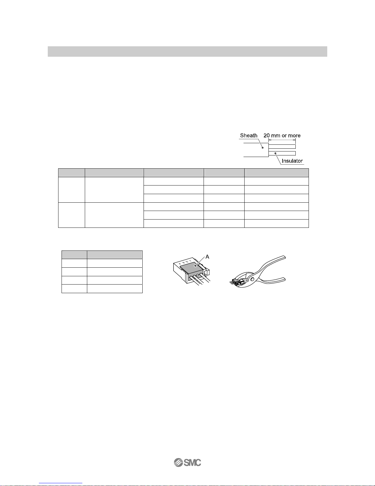
○Attaching the connector to the lead wire
•Sensor wire is stripped as shown in the right figure.
(Refer to the table below for correspondence between connector
and electrical wire gauge.)
Lead wire table
AWG No. Conductor size (mm2) Overall diameter (mm) Color of cover SMC product No. (1 pc.)
φ0.8 to φ1.0 Red ZS-28-C
φ1.0 to φ1.2 Yellow ZS-28-C-1
26-24
(28)
0.14-0.2
(0.08)
φ1.2 to φ1.6 Orange ZS-28-C-2
φ1.0 to φ1.2 Green ZS-28-C-3
φ1.2 to φ1.6 Blue ZS-28-C-4
22-20 0.3-0.5
φ1.6 to φ2.0 Gray ZS-28-C-5
•Do not cut the insulator.
•The core of the corresponding color shown in the following table is put into the pin of the number
stamped on the connector for sensor connection to the back.
Pin No.
Wire color
1 Brown (DC+)
2 NC
3 Blue (DC-)
4 Black (IN: 1 to 5 V)
•It checks that the above-mentioned preparation work has been performed correctly, and A part shown in
right figure is pushed by hand and makes temporary connection.
•A part center is straightly pushed in by tools, such as pliers.
•Re-use cannot be performed once it connects the connector for sensor connection completely. When you
fail in the connection mistake of a core and a pin, or the plug of wire, please use the new connector for
sensor connection.
•When the sensor is not connected correctly, [-----] or [---] can be displayed.
Page 17
-16-
No.PS##-OMH0006-C
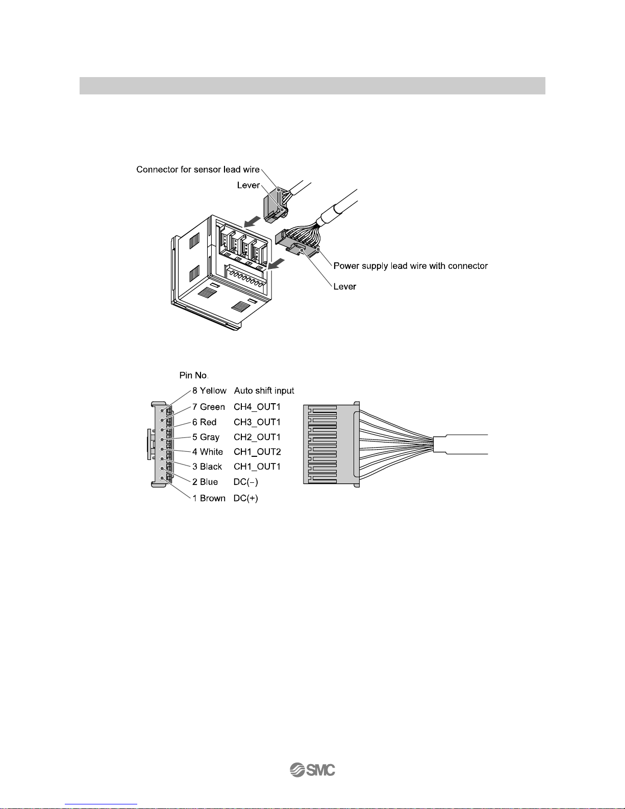
○Connector
Connecting/Disconnecting
•When connecting the connector, insert it straight onto the pin and lock the connector into the square
groove in the housing until connector clicks.
•When removing the connector, press down the lever with your thumb and pull the connector straight out.
Pin No. of the connector
Page 18
-17-
No.PS##-OMH0006-C
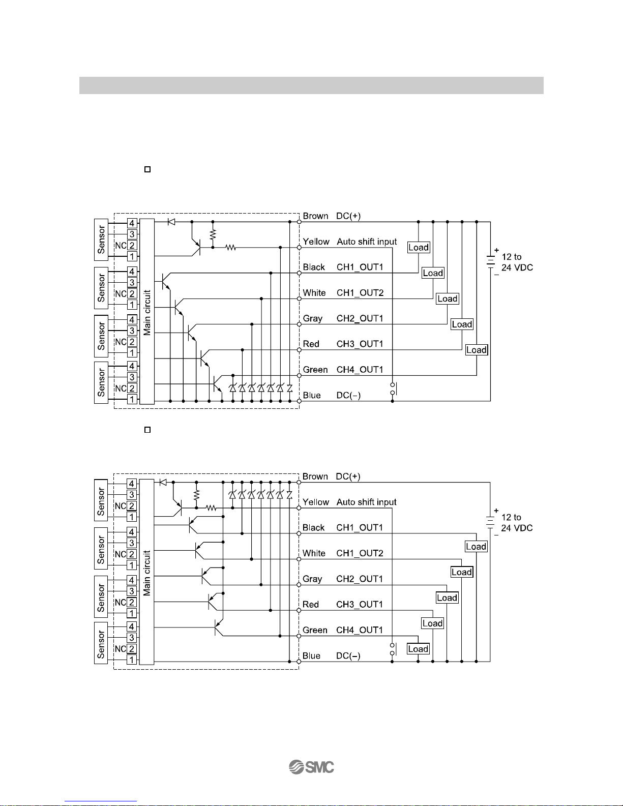
■Internal circuit and wiring example
○Output specification
When the lead wire with SMC power and output lead wire (Model: ZS-26-A) is used, the colors of wire
(Brown, Blue, White, Gray, Red, Green Yellow) will apply as shown on circuit diagram.
PSE200-(M) : NPN open collector 5 outputs + Auto-shift 1 input
Max. 30 V, 80 mA
Residual voltage 1 V or less
PSE201-(M) : PNP open collector 5 outputs + Auto-shift 1 input
Max. 80 mA
Residual voltage 1 V or less
Page 19
-18-
No.PS##-OMH0006-C
Setting of Function
○Setting procedures
Measurement mode
Detects pressure, displays values and performs switching.
Other functions such as zero clear can also be set if necessary.
For connecting at
least 1 sensor other
PSE530 series.
▼
Automatic identification
function release
▼
For connecting only
PSE530 series.
▼
Initial setting
Selection of Pressure range, Output style, Response time and Pressure setting method.
▼
Pressure Setting
Input of set value for pressure to perform switch output.
▼
Setting of Special Function
Selection or setting of Fine adjustment function of displayed value, Copy function, Auto-shift
function and Automatic identification function.
▼
Measurement mode
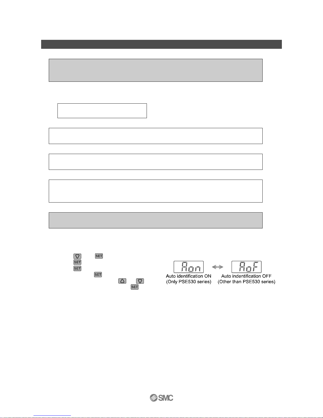
○Automatic identification function release
(When at least 1 sensor other than PSE530 series will be connected.)
•Press the and buttons are pressed simultaneously for 2 seconds or longer to display [FSt].
•Press the
button to display [CPy].
•Press the
button to display [SH1],
and then press the
button again.
•If [Aon] is displayed, press the
or button
to display [AoF], and then press the
button.
∗: Setting for the automatic identification function is ON when default setting.
Page 20
-19-
No.PS##-OMH0006-C
○Initial setting
Select the setting channel by pressing the button and keep pressing the button for 2 seconds or
longer. Initialize can get started. Initial setting is required for each channel.
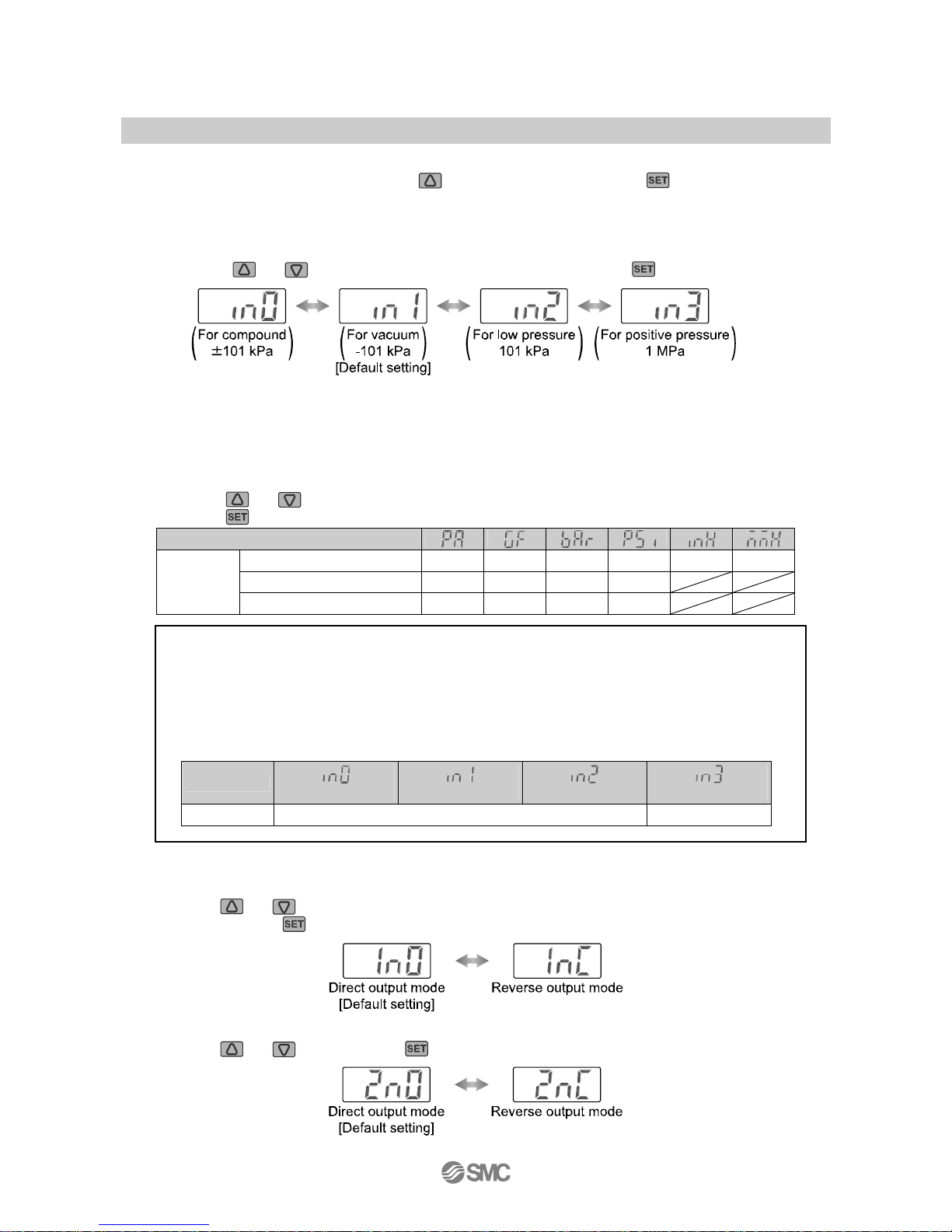
1, Setting of pressure range
•Select the pressure range suitable for the sensor connected.
•Press the
or button and select the pressure range. Press the button to set.
∗: When automatic identification mode is set, it is changed to pressure range of connected pressure sensor (Series PSE530 only)
when power is supplied.
∗: When range setting is changed, pressure set value changes. So conduct pressure setting again.
2, Selection of display unit (with unit conversion function)
The indication unit can be selected freely.
Press the
or button will change the unit and will automatically convert set values.
Press the
button to set and to move to setting the output mode.
LCD display
For compound and vacuum kPa kgf/cm
2
bar psi inHg mmHg
For low pressure kPa kgf/cm
2
bar psi
Unit label
For positive MPa kgf/cm
2
bar psi
In order to display the selected unit, the unit label according to the pressure range or the display
unit is attached.
Select and use an applicable label from the following table.
•In case [M] is assigned to unit specification in model indication.
Use the suitable label in the above labels by setup of the display unit.
•In case [M] is not assigned to unit specification in model indication.
The following unit displays light according to the setting of the pressure range.
LCD display
(Compound)
(Vacuum)
(Low pressure)
(Positive pressure)
Unit display kPa MPa
3, Setting of output style
1)The output style for OUT1 is set.
•Press
or button and select the normally open or the normally closed.
Next, press the
button to set.
2)The operating mode and the output style for OUT2 is set. (only CH1)
•Press
or button and the button to set, as in OUT1.
Page 21

-20-
No.PS##-OMH0006-C
•List of output mode
•If input pressure fluctuates around the set point when hysteresis is set at 2 digits or less in hysteresis
mode, switch output may cause chattering.
•Hysteresis is fixed at 3 digits in window comparator mode. When the pressure is set, the space of 7
digits at min. needs to be taken.
→The space below 7 digits does not allow the operation.
Page 22
-21-
No.PS##-OMH0006-C
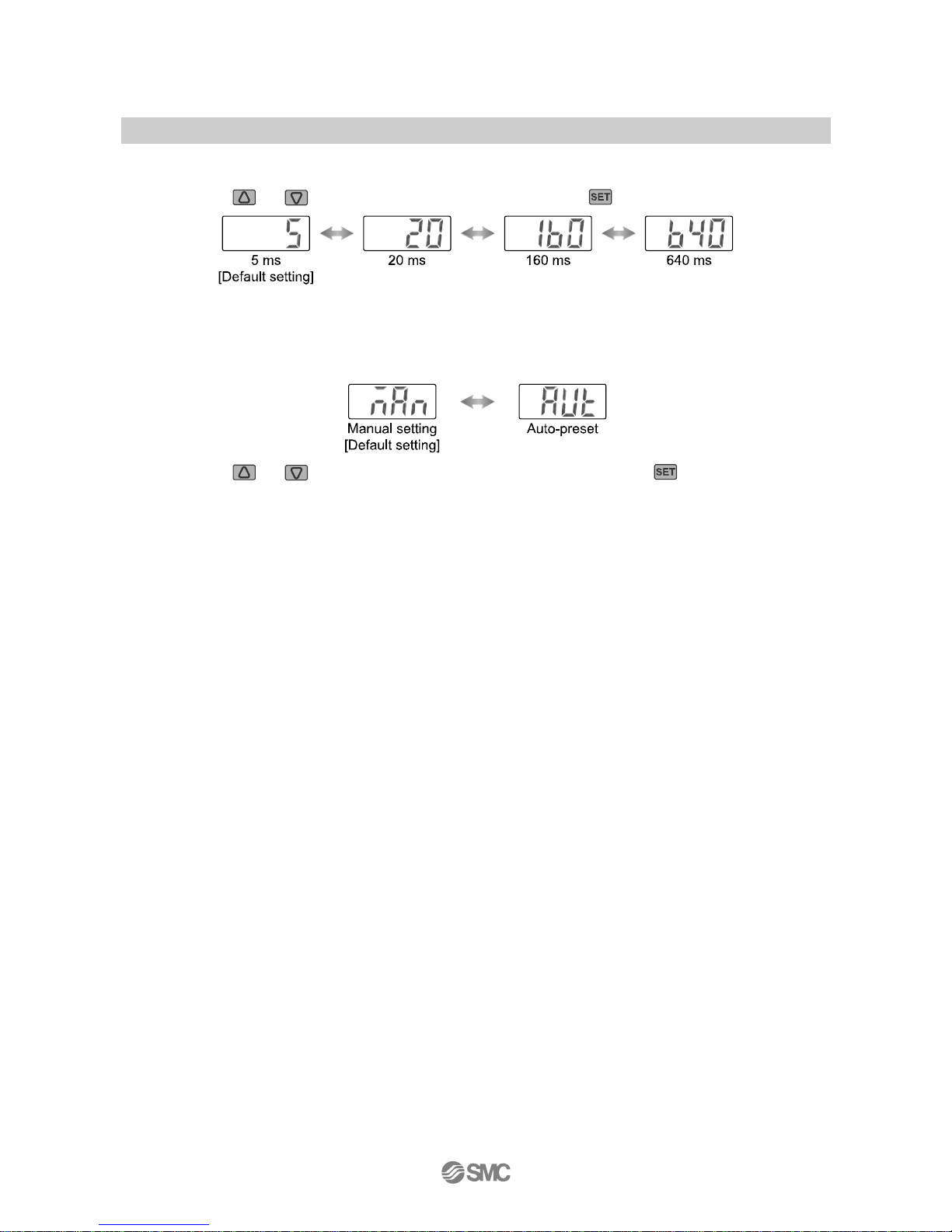
4, Setting of response time
•Set response time of switch output. Output chattering is prevented by setting the response time.
•Press the
or button to select response time. Press the button to set.
5, Selection of pressure setting method
•There are two methods for pressure setting: manual and auto-preset, either one of which can be
selected. The auto-preset is provided for an automatic optimum set-up by using a sample for a case in
which switch output is used to check absorption.
•Press the
or button to select pressure setting method. Press the button to set.
•All the setting mode will be completed and return to the measurement mode.
Page 23
-22-
No.PS##-OMH0006-C
Pressure Setting
○Manual setting
Manually set a set value of the controller. Pressure setting is made for respective channel.
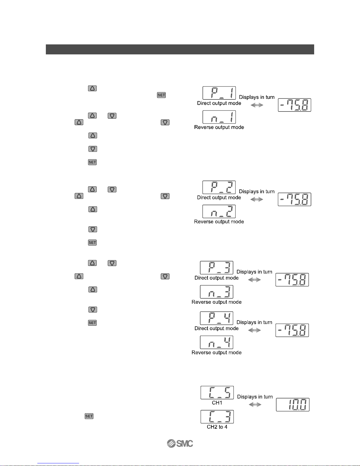
1, Selection of OUT1 [P_1] setting mode
•Press the
button during the Measurement mode
to select channel, and then, press the
button
to display set values.
•[P_1] or [n_1] and set value are displayed in turn.
•Press the
or button to change the set value.
The
button is for increase and the button
is for decrease.
Press the
button once to increase by one figure, and press it continuously to keep set figure
increased.
Press the
button once to decrease by one figure, and press it continuously to keep set figure
decrease.
•Press the
button to finish the setting.
2, Selection of OUT1 [P_1] setting mode
•[P_2] or [n_2] and set value are displayed in turn.
•Press the
or button to change the set value.
The
button is for increase and the button
is for decrease.
Press the
button once to increase by one
figure, and press it continuously to keep set figure
increased.
Press the
button once to decrease by one figure, and press it continuously to keep set figure
decrease.
•Press the
button to finish the setting.
3, Selection of OUT2 [P_3, P_4] setting mode (only CH1)
•Press the
or button to change the set
value as in 1, 2.
The button is for increase and the button
is for decrease.
Press the
button once to increase by one
figure, and press it continuously to keep set figure
increased.
Press the
button once to decrease by one figure,
and press it continuously to keep set figure decrease.
•Press the
button to finish the setting.
4, Auto-shift compensation value setting
•[C_5] ([C_3] for CH2 to CH4) and auto-shift
corrected Value will displayed in turn.
Without auto-shift input setting, Correction values
displays Zero.
•Press the
button to return to the measurement.
Page 24
-23-
No.PS##-OMH0006-C
○Auto-preset
When auto-preset is selected in initialize, the set pressure can be calculated and memorized from
measured value. The set value is automatically optimized by repeating the suction and release of the object
for the setting.
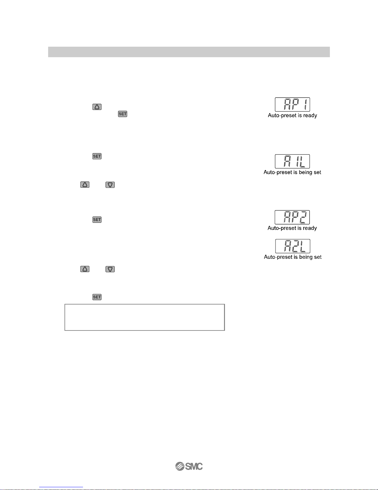
1, Selection of auto-preset OUT1
•Press the
button in Measurement mode to select channel,
and then, press the
button to display [AP1].
2, Preparation of OUT1 device
•Prepare the device for which the pressure of OUT1 is set.
3, Setting of auto-preset value of OUT1
•Press the
button to display [A1L].
•After measurement starts, operate the device and change the pressure.
•When the pressure change is detected, a set value will appear
automatically.
(The
and buttons are pressed simultaneously for 1 second or longer
in case OUT1 setting is not necessary, measurement is stopped and [AP2]
will appear.)
4, Selection of auto-preset OUT2
•Press the
button to display [AP2].
5, Preparation and setting of OUT2 device
•Prepare the device for which the pressure of OUT2 is set, and perform
the setting of OUT2 in the same manner as that for OUT1.
•After [A2L] is displayed and measurement starts, when the pressure
change is detected, a set value will appear automatically.
(The
and buttons are pressed simultaneously for 1 second or longer
in case OUT2 setting is not necessary, measurement mode returns.)
6, Completion of setting
•Press the
button and complete auto-preset mode. After that, measurement mode returns.
The set value are displayed in auto-preset as follows.
ON = A - (A - B)/4 A = Max. pressure
OFF = B + (A - B)/4 B = Min. pressure
Page 25
-24-
No.PS##-OMH0006-C
Setting of Special Function
○Fine adjustment function of displayed value
This makes no dispersion on CH1 to CH4 each output value, and make same displayed value.
It is possible to do fine adjustment within ±5%R.D. range of the reading data on the displayed value of
pressure sensor.
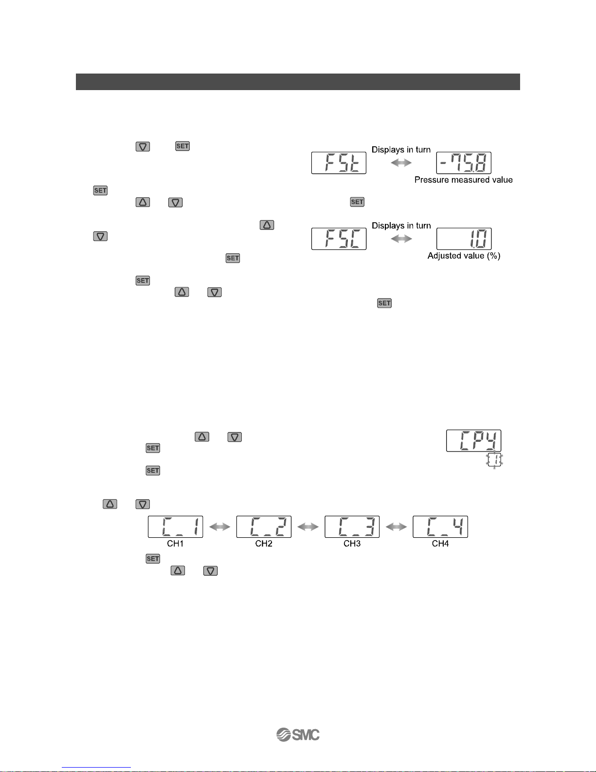
•Press the
and buttons are pressed
simultaneously for 2 seconds or longer to display
[FSt].
If fine adjustment is unnecessary, press the
button while [FSt] is displayed. Move to copy function.
•Press the
or button to select channel, and press the button.
•[FSt] and preset pressure measured value are in turn.
•Increase or decrease value by press the
or
button.
(It is possible to increase/decrease within ±5%R.D.)
•Check the value, then press the
button.
[FSC] and the adjusted value (%) are displayed in turn.
•Press the
button to return display of [FSt]. Perform display of [FSt] setting of other channels like the
above by press the
or button.
•After setting of other channels in [FSt] display is completed, press the
button there.
Move to copy function.
∗: When fine adjustment mode is conducted, pressure setting value is sometimes changed by ±1 digit
○Copy function
1, 5 items such as pressure setting value, pressure range, display unit, output style and response time are
copied.
2, If copied from CH1 to CH2, CH3 and CH4, CH1 OUT1 information is copied.
CH2, CH3 and CH4 information are copied only into OUT1 of CH1 if copied from CH2, CH3 and CH4 to
CH1.
•[CPy] is displayed. Selection of channel to be copied displayed in channel
indicator by press the
or button.
•Press the
button in case copy mode setting is not necessary.
Move to auto-shift function.
•Press the
button so that the channel display of a copied material changes
from blink to lighting.
•[CPy] and the channel to be pasted will flicker alternately. Next, select channel to be pasted by press the
or button.
•Press the
button, and return to [CPy] display.
•Again press the
or button and the same operation is repeated to copy other channel.
•After setting is completed, move from [CPy] display to auto-shift mode.
∗: When copy function is conducted, pressure setting value is sometimes changed by ±1 digit.
Page 26
-25-
No.PS##-OMH0006-C
○Auto-shift function
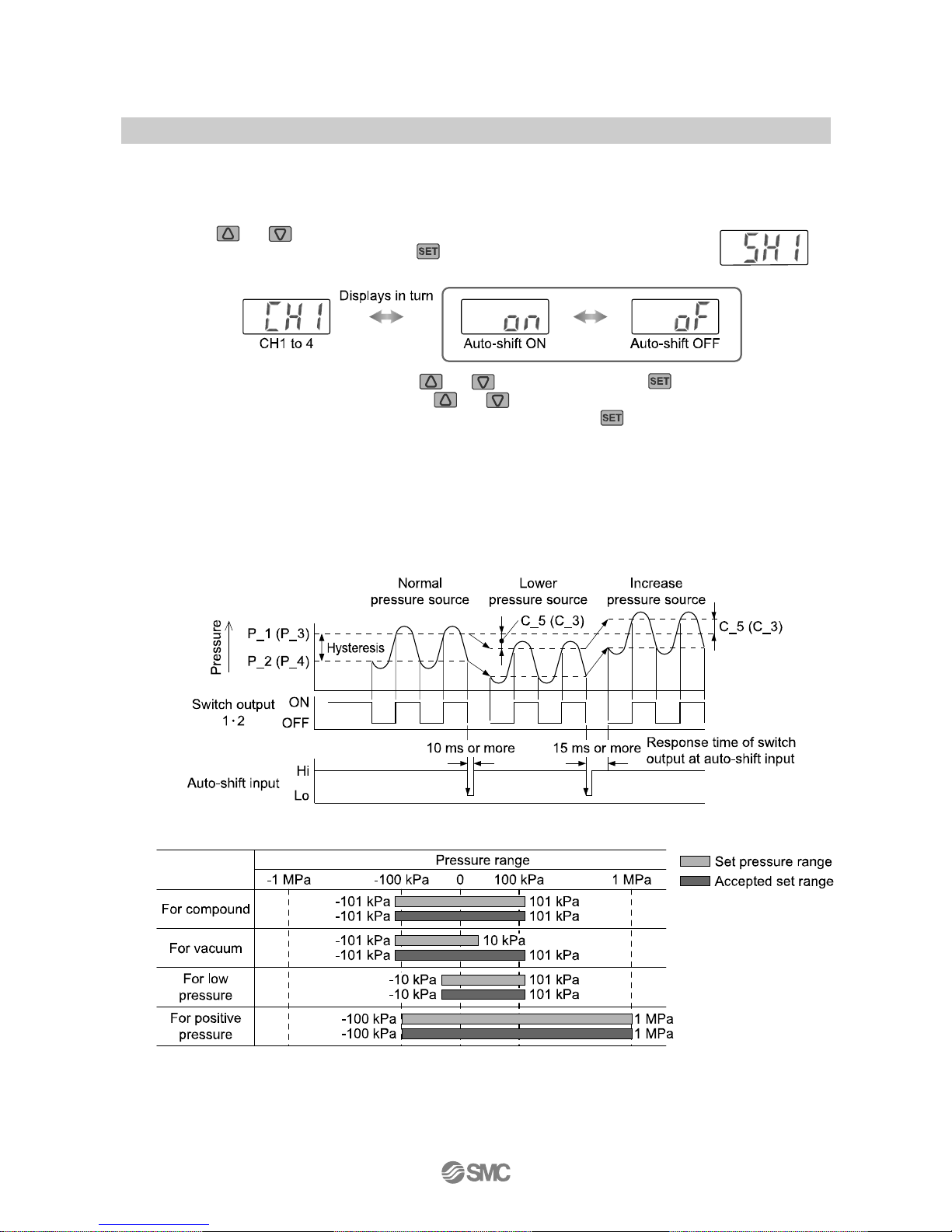
This function corrects the setting value of each switch output according to change of pressure source. Even if pressure
source is changed, this can do correct decision on switch output.
Refer to below or page 26 for detail.
•Press the
or button in the state where [SH1] is displayed, and [CH1] and
[on]/[oF] will flicker alternately. Press the
button with the indication of [SH1]
makes it move to the automatic identification function.
•Selection of auto-shift mode by press the
or button, and press the button.
•Similarly, [CH2], [CH3] and [CH4] press the
or button, and selection of auto-shift mode.
•After auto-shift mode setting of all channels is completed, if press the
button, it will move to
automatic identification function.
○About auto-shift function
This function corrects the setting value of each switch output according to change of pressure source.
Even if pressure source is changed, this can do correct decision on switch output.
•Correction of setting value by auto-shift use
•Using with auto-shift input, accepted setting range is like below
Page 27
-26-
No.PS##-OMH0006-C
○Conditions and explanations for auto-shift function
•Keep constant pressure for 10 ms or longer from the close signal of auto-shift input.
•At auto-shift input, [ooo] is displayed for approximate 1 second. Pressure value at that time is memorized
as corrected value [C_5] or [C_3].
•The switch set as auto-shift mode at the time of initial setting operates with the value which applied
corrected value [C_5] or [C_3] to setting value.
•CH1 will operate with auto-shift function.
The operate value of OUT1 applies corrected value [C_5] to the setting value [P_1] to [P_4] or [n_1] to
[n_4].
•CH2 to CH4 will operate with auto-shift function
The operate value of OUT1 applies corrected value [C_3] to the setting value [P_1] and [P_2] or [n_1]
and [n_2].
•Span is 15 ms or less until the switch output starts soon after auto-shift input.
•When corrected measured value exceed the set pressure range with auto-shift input, the value is changed
to be within the range of set pressure.
•When auto-shift function is turned off, corrected value becomes zero.
•When auto-shift function of all channels is turned off, even if auto-shift input is Lo (Non voltage input) does
not show [ooo].
•Corrected value after auto-shift input will vanish when the power is off, and is reset to zero (Initial value)
when the power is off, and is reset to zero (Initial value) when the power is re-supplied.
∗: EEPROM is not used for memory corrected value.
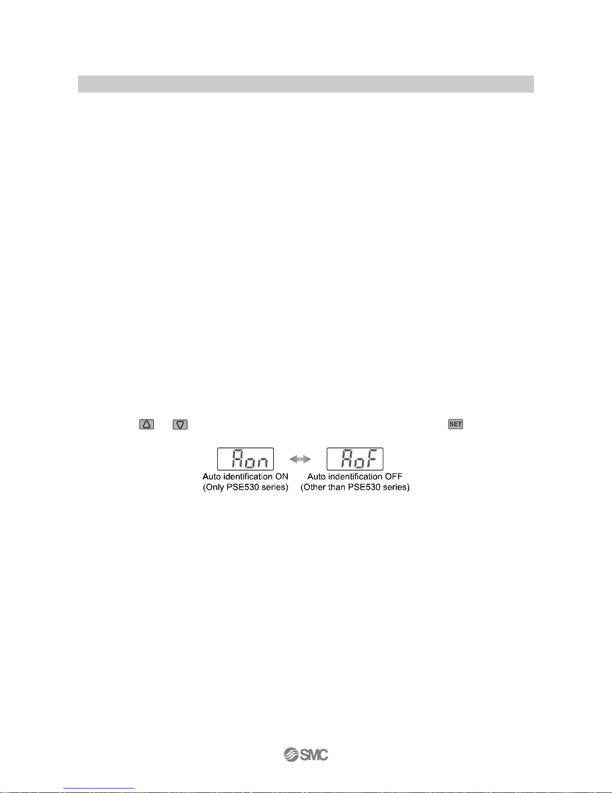
○Automatic identification function
This function identifies pressure range of pressure sensor connected to this controller. When [Aon] is set at
the automatic identification mode, and when re-applied power at [Aon] status, this function actuates.
(Special pressure sensor (SMC PSE530 series) is applicable to this function. Other pressure sensor is not
applicable.)
•Press the
or button to select automatic identification mode, and press the button.
•All the setting mode will be completed and return to the measurement mode.
Page 28
-27-
No.PS##-OMH0006-C
Other Settings
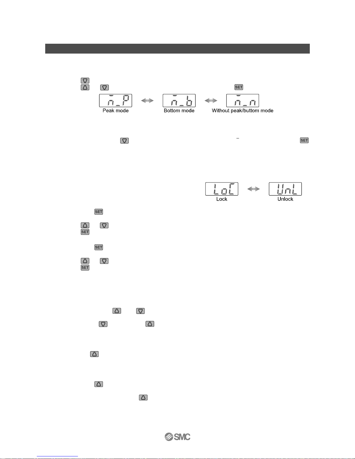
○Peak/Bottom hold indication
Maximum and minimum values are always detected and updated during measurement.
Displayed values can be hold.
•Press the
button for 2 seconds or longer.
•Press the
or button to select peak/bottom mode, and press the button.
•Peak mode: Flickers the maximum pressure value.
•Bottom mode: Flickers the minimum pressure value.
•w/o peak/bottom mode: Return to the measurement mode.
•To release hold, press the
button for 2 seconds or longer, then select [n_n] and finally press the
button.
•When each setting or each mode operation is performed, the “Peak and Bottom hold indication" is
released.
○Key lock function
A wrong operation performed unintentionally such as change
of set value can be prevented.
Set [LoC] (lock mode) in order not to accept button operation.
Lock
•Keep press the
button for 4 seconds or longer.
Remove the finger off the button when [UnL] is displayed.
•Press the
to button to set the display to [LoC].
•Press the
button makes it move to the measurement mode.
Release
•Keep press the
button for 4 seconds or longer.
Remove the finger off the button when [LoC] is displayed.
•Press the
to button to set the display to [UnL].
•Press the
button makes it move to the measurement mode.
∗: For a "Channel selects function" and "Channel scans function", the "Key lock function" does not work.
○Zero clear
A displayed value can be adjusted to zero when the pressure to be measured is within ±5%F.S. (±2.5%F.S.
for compound pressure) of the pressure at the ambient pressure.
•Press continuously the
and buttons for 1 second or longer simultaneously, display is cleared as
“0”.
Please press the
button before button first, channel select function may operate.
•Return to the measurement mode automatically.
○Channel selects
•Per one push button, channel selection can be done, like “1→2→3→4→1→…”.
Display shows pressure value, which is measured at the channel selected.
○Channel scans
•Keep press the button for 2 seconds or longer. If changes indicating the channel indicated ever 2
seconds and measuring pressure corresponding with it.
•To release this function, press the
button again for 2 seconds or longer.
Page 29

-28-
No.PS##-OMH0006-C
Maintenance
How to reset the product for power cut or forcible de-energizing
The setting of the product is remained as that before power cut or de-energizing.
The output condition is also basically recovered to that before power cut or de-energizing, but may change
depending on the operating environment. Therefore, check the safety of whole facility before operating the
product.
If the facility is under accurate control, wait until it has warmed up. (Approximate 20 to 30 minutes)
Page 30
-29-
No.PS##-OMH0006-C
Troubleshooting
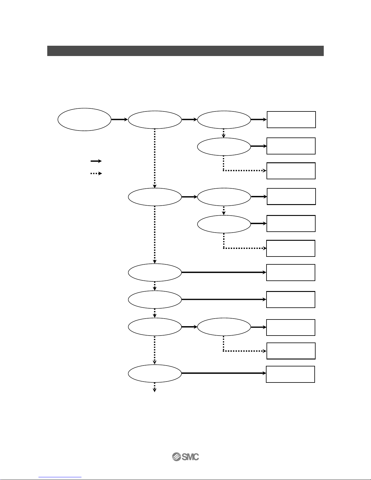
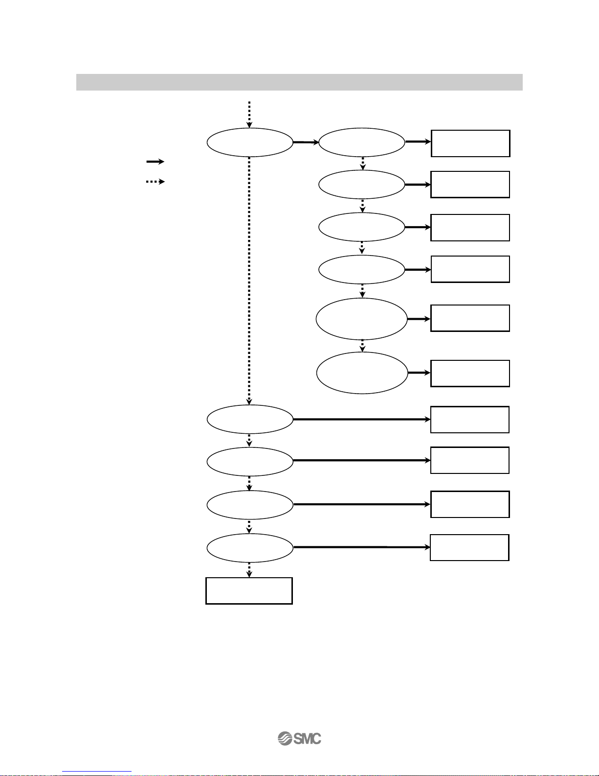
○Troubleshooting
Applicable pressure switch: PSE200
If a cause applicable to the failure cannot be identified and normal operation can be recovered by
replacement with a new Pressure switch, this indicates that the Pressure switch itself was broken. The
Pressure switch breakage can be caused by operating environment (network construction, etc.), and so
consult with SMC separately to obtain countermeasures.
Yes
No
The pressure
switch does not
operate normally
Refer to reference
No.1
The switch out
p
ut is on
The indication light is on
The indication light
works improperly
The switch output is off
The switch output
generates chattering
The indication light is off
The indication light
is on or off
The indication light is off
The indication li
g
ht is on
The product is
broken
Refer to reference
No.2
Refer to reference
No.1
Refer to reference
No.4
Refer to reference
No.3
The product is
broken
The product is
broken
The product is
broken
Slow switch output
response
Refer to reference
No.5
An error signal comes on
Refer to reference
No.6
Page 31
-30-
No.PS##-OMH0006-C
The unit cannot be
changed
The buttons cannot be
operated
The display fluctuates
There is a noise
The body has become
loose
The display disappears
The display flashes
Pressure indication
difference when using
two or more pressure
switches
Refer to reference
No.7
The dis
play
is abnormal
Refer to reference
No.8
Refer to reference
No.8
Refer to reference
No.10
Refer to reference
No.13
Refer to reference
No.12
Refer to reference
No.14
Refer to reference
No.15
The display breaks off
Refer to reference
No.16
Refer to reference
No.9
The indication
accuracy does not
satisfy the
specifications
Refer to reference
No.11
Yes
No
Page 32
-31-
No.PS##-OMH0006-C
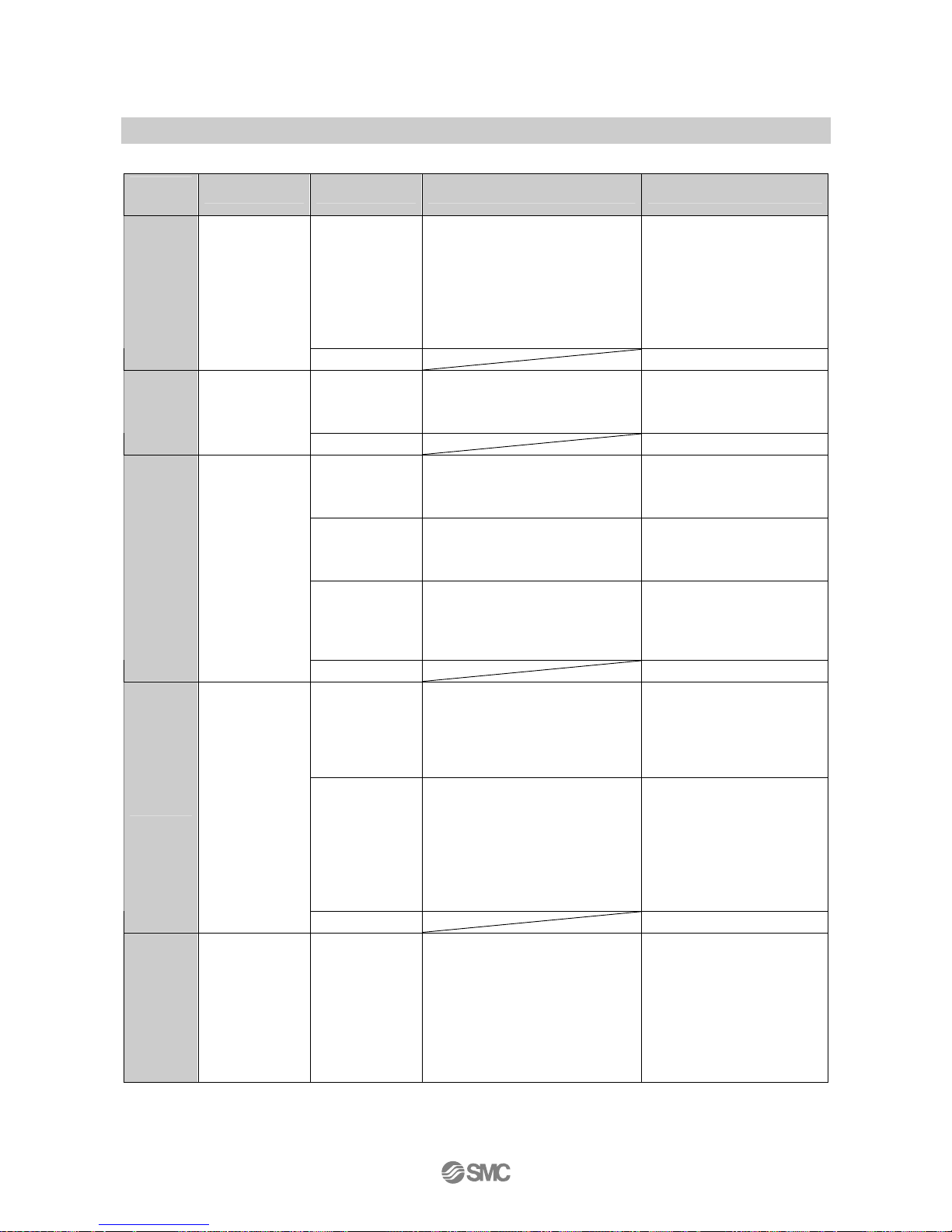
○Cross-reference for troubleshooting
Reference
No.
Problem Possible cause Investigation method Countermeasure
Wrong pressure
setting
(1)Check the set pressure.
(2)Check the settings of the
operation mode, hysteresis and
output style.
(Hysteresis mode/window
comparator mode, normal
output/reversed output)
(1)Reset the pressure setting.
(2)Reset the setting of
function.
1
•Output remains
on.
Indication light
remains on.
•Output remains
off.
Indication light
remains off.
Product failure
Replace the product.
Incorrect wiring
Check the wiring of the output line.
Check if the load is connected
directly to DC(+) or DC(-).
Correct the wiring.
2
Output remains
on.
Indication light
works correctly.
Product failure
Replace the product.
Incorrect wiring
Check the wiring of the output line.
Check if the load is connected
directly to DC(+) or DC(-).
Correct the wiring.
Unsuitable
model selection
Check if PNP is used even though
NPN should have been selected, or
the other way around.
Review the selected model
(output type).
Lead wire
breakage
Check if there is bending stress
applied to any parts of the lead
wire. (Bending radius and tensile
force applied to the lead wire)
Correct the wiring conditions.
(Adjust the tensile force and
widen the bending radius.)
3
Output remains
off.
Indication light
works correctly.
Product failure
Replace the product.
Incorrect wiring
Check the wiring.
Check if the brown and blue wires
are connected to DC(+) and DC(-)
respectively, and if the output line is
about to come off (contact failure).
Correct the wiring.
Wrong setting
(1)Check the set pressure.
(2)Check if the hysteresis range is
too narrow.
(3)Check the response time set as
initial setting.
Check if the response time is too
short.
(1)Reset the pressure setting.
(2)Widen the hysteresis.
(3)Reset the setting of
function.
4
Switch output
generates
chattering.
Product failure
Replace the product.
5
Slow switch
output response
Incorrect
pressure setting
(1)Check the pressure setting.
Check if the detected pressure
and the set pressure value have
the same value or are too close.
(2)Check the response time set as
initial setting.
Check if the response time is too
long.
(1)Reset the pressure setting.
Set up the pressure setting
value so it is not too close
to the detected pressure
value.
(2)Reset the setting of
function.
Page 33

-32-
No.PS##-OMH0006-C
Reference
No.
Problem Possible cause Investigation method Countermeasure
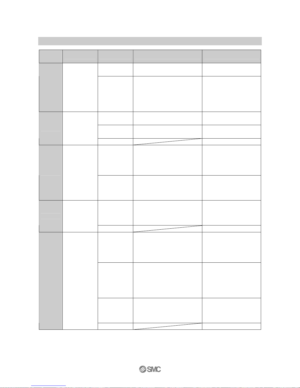
Over current to
the output
(Er1 and 2)
(1)Check if a current of 80 mA or
more is flowing to the output.
(2)Check if the connected load
satisfies the specifications, and if
the load is shorted.
(3)Check if a relay without a surge
voltage suppressor is connected.
(4)Check if the wiring is in the same
route as (or bundled together
with) a high-voltage line or the
power line.
(1),(2)Connect the load as
specified.
(3)Use a relay with a surge
voltage suppressor or take
a measure to prevent
noise.
(4)Separate the wiring from
the high-voltage line and/or
power line.
Improper
transaction of
the internal data
of the Pressure
switch
(Er5, 6, 7, and 8)
(1)Check if there is noise
interference such as static
electricity. Check if there is a
noise source
(2)Check if the power supply
voltage is in the range of 12 to
24 VDC.
(1)Remove the noise and the
noise source (or take
measures to prevent noise
interference), and turn off
the power supply. Then,
supply the power again.
(2)Supply power voltage of 12
to 24 VDC.
Applied pressure
is over the upper
limit (---).
(1)Check if the pressure gets over
the upper limit of the set
pressure range.
(2)Check if foreign matter got into
the piping.
(3)The connector for sensor may
not be connected correctly.
(1)Bring the pressure back
within the set pressure
range.
(2)Take measures to prevent
foreign matter from getting
into the piping.
(3)Check the wires and
contact of the connector for
sensor.
Applied pressure
is under the
lower limit (----).
(1)Check if the pressure gets below
the lower limit of the set pressure
range.
(2)Check if foreign matter got into
the piping.
(3)The connector for sensor may
not be connected correctly.
(1)Bring the pressure back
within the set pressure
range.
(2)Take measures to prevent
foreign matter from getting
into the piping.
(3)Check the wires and
contact of the connector for
sensor.
Pressure is not
atmospheric
pressure at
zero-clear
operation (Er3)
Check if the pressure over ±5%F.S.
(±2.5%F.S. for compound
pressure) of the atmospheric
pressure is applied.
Return the applied pressure
to atmospheric pressure, and
retry the zero clear operation.
6
•An over current
error (Er1 and
2) is indicated.
•System error
(Er5, 6, 7, and
8) is indicated.
•The display
shows "---".
•The display
shows "----".
•Zero-clear error
(Er3) is
indicated.
Product failure Replace the product.
Page 34
-33-
No.PS##-OMH0006-C
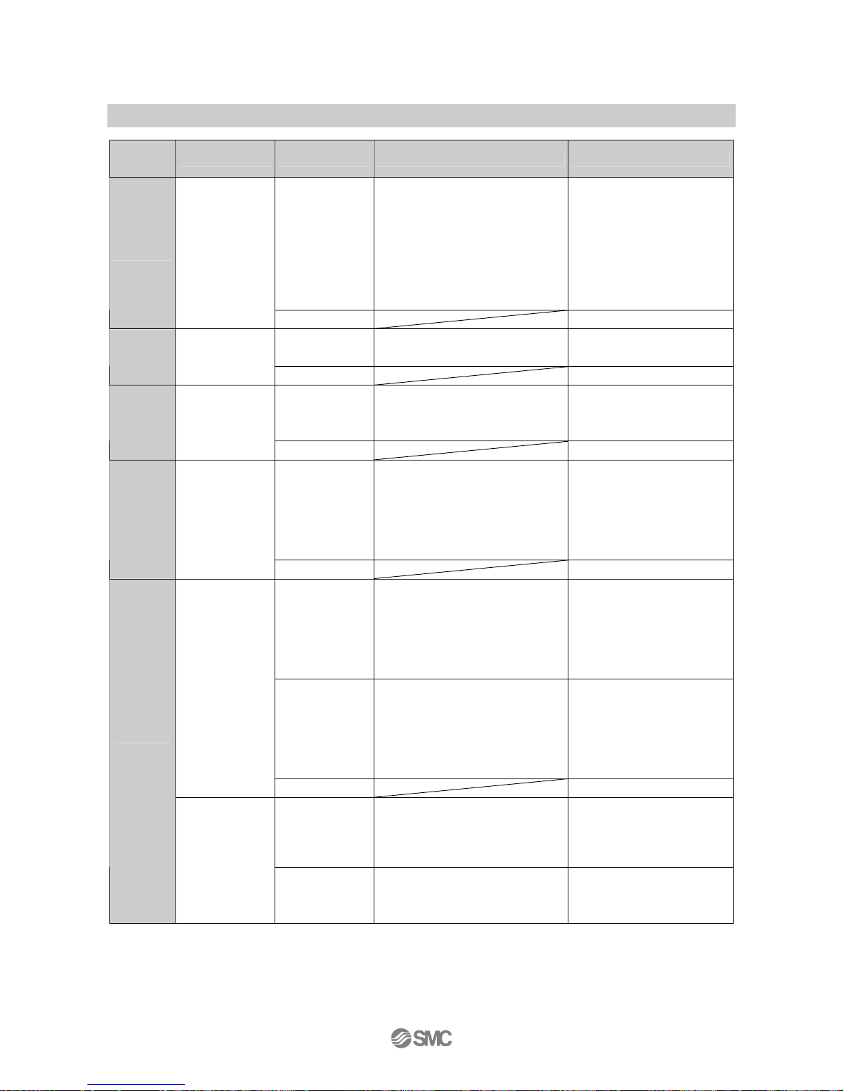
Reference
No.
Problem Possible cause Investigation method Countermeasure
Incorrect power
supply
Check if the power supply voltage
is within the range of 12 to 24 VDC.
Supply power supply voltage
of 12 to 24 VDC.
7
Indicated values
fluctuate.
Incorrect wiring
Check the wiring to the power
supply.
Check if the brown and blue wires
are connected to DC(+) and DC(-)
respectively and if the output line is
about to come off (contact failure).
Correct the wiring.
Incorrect power
supply
Check if the power supply voltage
is within the range of 12 to 24 VDC.
Supply power supply voltage
of 12 to 24 VDC.
Power saving
mode
Check if the power saving mode is
selected.
Reset the setting of function.
8
•Indicator turns
off.
•A part of the
indication
misses.
Product failure Replace the product.
The peak
value/bottom
value indication
mode is
selected.
Check if the peek value or bottom
value indicating mode is selected.
Turn off the peak
value/bottom value indication
mode.
9
Indicator is
blinking.
Wiring failure
(1)Check the power supply wiring.
(2)Check if bending stress is being
applied to a specific part of the
lead wire.
(1)Correct the wiring.
(2)Correct the wiring (bending
radius and stress).
Dispersion within
the indication
accuracy range
Check if the dispersion is within the
indication accuracy range.
Use the fine adjustment mode
to adjust the indication if the
dispersion is within the
indication accuracy range.
10
Pressure indication
difference when
using two or more
Pressure switches.
Product failure Replace the product.
Foreign matter
Check if foreign matter has entered
the pressure port.
Install a 5 µm filter to prevent
foreign matter from getting into
the pressure port. Also, clean
the filter regularly to prevent
drainage deposits.
Air and liquid
leakage
Check if air and liquid are leaking
from the piping.
Rework the piping.
If excessive tightening torque
over the specified range is
applied, a mounting screw,
mounting bracket, and product
may be broken.
Insufficient
warm-up
Check if the product satisfies the
specified accuracy 20 minutes after
supplying power.
After energizing, indication
can drift. For detecting fine
pressure, warm up the product
for 20 to 30 minutes.
11
The pressure
indication
accuracy does
not satisfy the
specifications.
Product failure
Replace the product.
Page 35
-34-
No.PS##-OMH0006-C
Reference
No.
Problem Possible cause Investigation method Countermeasure
Improper model
selection
(Selection of
model "without
unit conversion
function")
Check if there is a "-M" at the end of
the part number printed on the
product
"M" in the part number means
that the unit cannot be
changed.
∗: The unit change function is not
available in Japan due to a new
measurement law.
∗: It is fixed to the SI unit "kPa",
"MPa".
12
The unit cannot
be changed.
Product failure
Replace the product.
Key lock mode
Check if the key lock mode is turned
on.
Turn off the key lock mode.
13
The buttons
cannot be
operated.
Product failure
Replace the product.
Incorrect
installation
Check that the panel mounting
adapter and the body are firmly
engaged.
Mount the body on the panel
properly.
14
The body is
loose.
Product failure
Replace the product.
Air and liquid
leakage
Check if air liquid are leaking from
the piping.
Rework the piping.
If excessive tightening torque
over the specified range is
applied, a mounting screw,
mounting bracket, and product
may be broken.
15
Noisy.
Product failure
Replace the product.
Effect of
pressure source
fluctuation due to
small hysteresis
or too early of a
response time
(1)Check the set pressure
(hysteresis)
(2)Check the response time
(1)Check the pressure
setting.
(2)Reset the setting of
function.
Incorrect wiring/
lead wire
breakage
(1)Check the power supply wiring.
(2)Check if bending stress is
applied to a specific part of the
lead wire.
(bending radius and tensile force
applied to the lead wire)
(1)Correct the wiring
(2)Correct the wiring
conditions. (Adjust the
tensile force and widen the
bending radius.)
The operation is
unstable.
(Chattering)
Product failure
Replace the product.
The automatic
identification
function is turned
on.
Check the setting by the automatic
identification function.
Turn off the setting if it is on.
16
The setting
changes.
A sensor other
than PSE530 is
connected.
Check the part number of the
sensor.
Turn off the setting if the
sensor is not PSE530.
Page 36
-35-
No.PS##-OMH0006-C
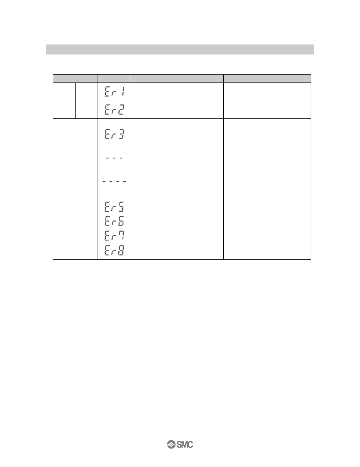
○Error indication function
This function is to display error location and content when a problem or an error occurs.
Error Name Error Display Error Type Troubleshooting Method
OUT1
Over
current
Error
OUT2
A load current of switch output is 80 mA
or more.
Turn the power off and remove the
output factor for the over current.
Then turn the power on.
Zero-clear Error
During zero clear operation, pressure
over ±5%F.S. (±2.5%F.S for compound
pressure) is applied. After 2 s, the mode
will reset to the measurement mode.
Perform zero clear operation again
after restoring the applied pressure to
an atmospheric pressure condition.
Pressure has exceeded the upper limit
of the set pressure range.
Pressurizing Error
A sensor has the possibility of
un-connecting and miswiring.
Pressure has exceeded the lower limit of
the set pressure range.
Check connection and wiring of a
sensor. And reset applied pressure to
a level within the set pressure range.
System Error
Displayed in the case of an internal data
error.
Turn the power off and turn it on again.
If resetting fails, an investigation by
SMC CORPORATION will be
required.
If the error can not be reset after the above measures are taken, then please contact SMC.
Page 37
-36-
No.PS##-OMH0006-C
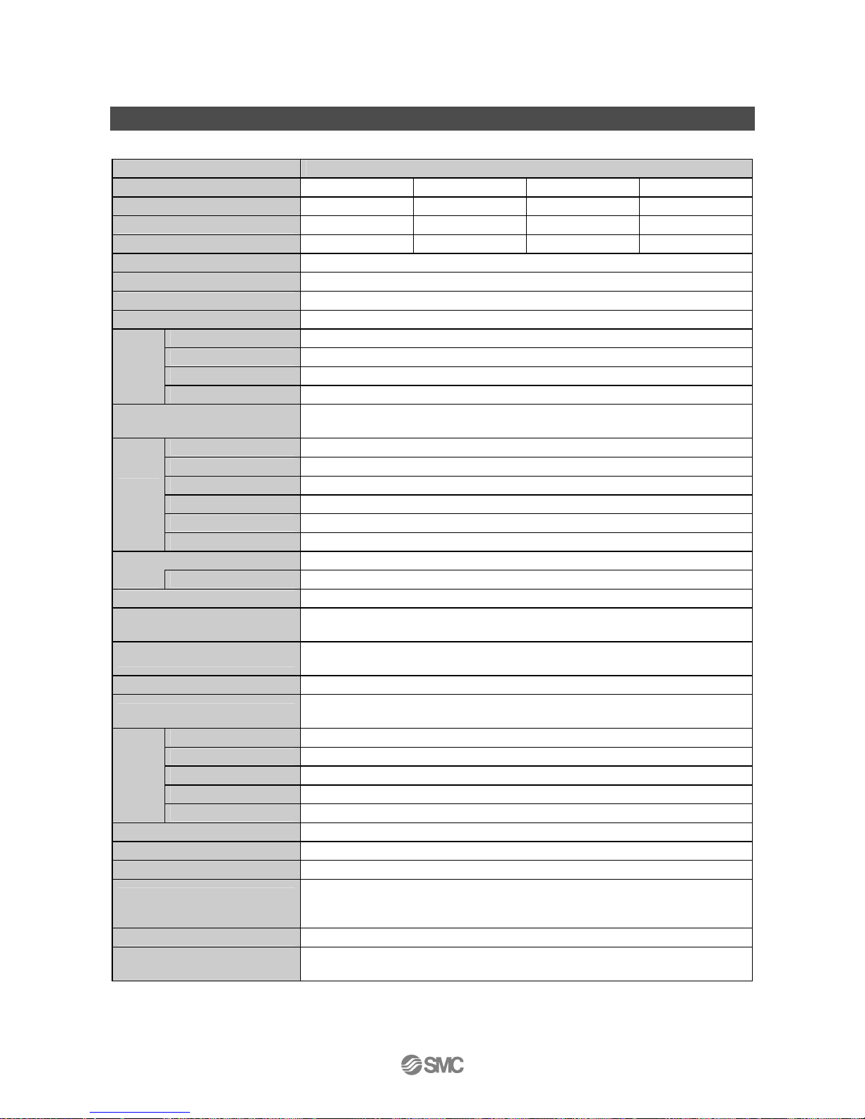
Specification
■Specifications
Model No. PSE20∗
Pressure range
∗1
For positive pressure For vacuum For low pressure For compound
Rated pressure range 0 to 1 MPa 0 to -101 kPa 0 to 101 kPa -101 to 101 kPa
Set pressure range -0.1 to 1 MPa 10 to -101 kPa -10 to 101 kPa -101 to 101 kPa
Setting/Display resolution 0.1 kPa 0.1 kPa 0.1 kPa 0.001 MPa
Power supply voltage 12 to 24 VDC, ripple (p−p) 10% or less (Protected against inverse connection)
Current consumption 55 mA or less (Except for consumed current of sensor part)
Power supply voltage for sensor [Power supply voltage] -1.5 V
Power supply current for sensor Max. 40 mA or less (Max. total consumed current is 100 mA for inputting 4 sensors)
∗2
Input signal 1 to 5 VDC (Input impedance: Approx. 800 kΩ)
Number of input 4 inputs
Input protection With over voltage protection (Applicable to voltage up to 26.4 V)
Sensor
input
Automatic identification Provided
∗3
Hysteresis
Hysteresis mode: Variable
Window comparator mode: Fixed 3 digits
Output style NPN or PNP open collector output
Number of output 5 outputs (2 outputs for sensor input CH1, and 1 output for each CH2 to CH4)
Max. load current 80 mA
Max. applied voltage 30 VDC (At NPN output)
Residual voltage 1 V or less (At 80 mA load current)
Switch
output
Output protection With short circuit protection
Response time 5 ms or less
Anti-chattering function 20, 160, 640 ms selectable
Repeatability ±0.1%F.S. ±1 digit
Indicator accuracy
(Ambient temp. 25 oC)
±0.5%F.S. ±1 digit
Display method
Display for measured value: 4 digits, 7-segment (Orange)
Display for channel: 1 digit, 7-segment (Red)
Indicator Light when ON (Red)
Auto-shift input
Non-voltage input (Reed or solid state), Input 10 ms or less,
Setting ON/OFF is possible independently
Enclosure Front part: IP65 (At panel mounting), Others: IP40
Ambient temp. range Operation: 0 to 50 oC, Storage: -10 to 60 oC (No condensation or freezing)
Ambient humidity
Operation, Storage: 35 to 85%RH (No condensation)
Withstand voltage 1000 VAC, 1 minute Between lead block and case
Environ
ment
Insulation resistance 50 MΩ or more (At 500 VDC) Between lead block and case
Temp. characteristics ±0.5%F.S. (25 oC reference)
Connection Power supply and output connection: 8P connector, Sensor connection: e-con
Standard CE, RoHS
Power supply/Output connection
cable
Oil resistance vinyl cabtyre cable 8 cores φ4.8 2 m
Sectional area of conductor: 0.15 mm
2
Outside diameter of insulator: 0.9 mm
Material Body: PBT, Display: Transparent nylon, Rubber cover for the back: CR
Weight
113 g (Power supply and output lead wire cable included)
55 g (Power supply and output lead wire cable not included)
∗1: Select pressure range by the initialization.
∗2: Over current on Vcc side and 0 V side of sensor input connector results in breakage of internal parts of controller.
∗3: Pressure sensor that automatic identification can be applied is only “PSE530 series”. Refer to page 18, 26 “Automatic identification
function” for detail.
Page 38
-37-
No.PS##-OMH0006-C
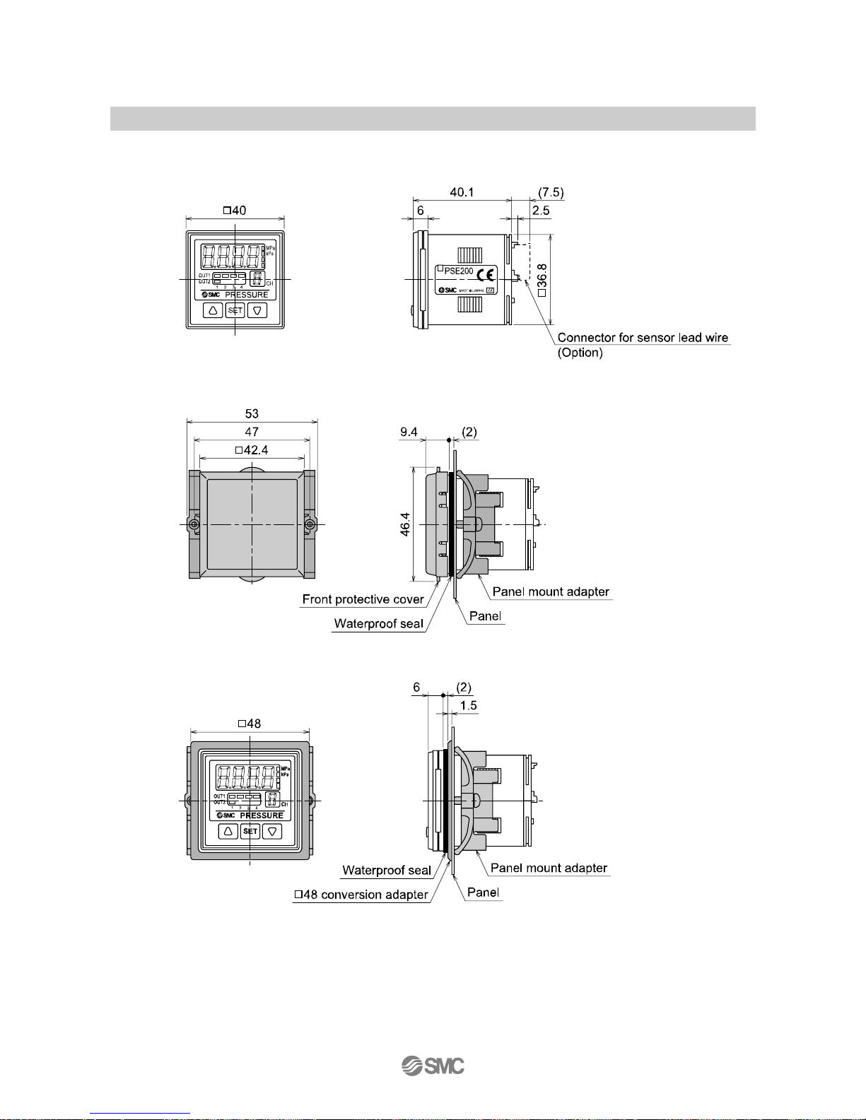
■Dimensions
○Body dimensions
•Panel mount adapter + Front protective cover
•Panel mount adapter + □48 conversion adapter
Page 39
No.PS##‑OMH0006‑C
Revision history
A: Addition of notes related to automatic
identification function
B: New publication for additional notes.
C: Revision
Note: Specifications are subject to change without prior notice and any obligation on the part of the manufacturer.
© 2009-2010 SMC Corporation All Rights Reserved
 Loading...