

SMC Networks ProtoCessor FPC-ED2 Startup Manual
Document Revision: 2.A
Web Configurator
Template Revision: 69
APPLICABILITY & EFFECTIVITY
Explains ProtoCessor hardware and how to install it.
The instructions are effective for the above as of November 2017.
BULLETIN NUC-PSUG-1
For Interfacing Leonard Valve Products: Valve
To Building Automation Systems:
BACnet MS/TP, BACnet/IP, Modbus TCP/IP, Modbus RTU,
Metasys N2 and EtherNet/IP
ProtoCessor FPC-ED2
Start-up Guide

Leonard Valve ProtoCessor Start-up Guide
Technical Support
Thank you for purchasing the ProtoCessor for Leonard Valve.
Please call Leonard Valve for Technical support of the ProtoCessor product.
Sierra Monitor Corporation does not provide direct support. If Leonard Valve needs to escalate the
concern, they will contact Sierra Monitor Corporation for assistance.
Support Contact Information:
Leonard Valve
1360 Elmwood Avenue
Cranston, RI 02910
Customer Service:
(401) 461-1200
(800) 222-1208
Website: leonardvalve.com
Email: info@leonardvalve.com
Page 2 of 32

Leonard Valve ProtoCessor Start-up Guide
Quick Start Guide
1. Record the information about the unit. (Section 3.1)
2. Set the COM settings for the device connected to ProtoCessor. (Section 3.3)
3. Connect ProtoCessor FPC-ED2’s 3 pin RS-485 port to the Field Protocol cabling. (Section 4.2)
4. Use a browser to access the ProtoCessor’s embedded tool, which is referred to in this manual as
the Web Configurator, to select the device that will be attached to ProtoCessor. Once the device
is selected, the ProtoCessor Automatically builds and loads the Configuration. (Section 5)
5. BACnet/IP, Modbus TCP/IP or EtherNet/IP: Use a browser to access the ProtoCessor Web
Configurator to change the IP Address. No changes to the configuration are necessary. (Section
5.5)
Page 3 of 32
Leonard Valve ProtoCessor Start-up Guide
TABLE OF CONTENTS
1 Certifications ........................................................................................................................................ 6
1.1 BTL Mark – BACnet® Testing Laboratory ....................................................................................... 6
2 Introduction .......................................................................................................................................... 7
2.1 ProtoCessor Gateway..................................................................................................................... 7
3 Setup for ProtoCessor ........................................................................................................................ 8
3.1 Record Identification Data .............................................................................................................. 8
3.2 Point Count Capacity and Registers per Device ............................................................................ 8
3.3 Configuring Device Communications ............................................................................................. 8
3.3.1 Input COM Settings on the Device Connected to the ProtoCessor .......................................... 8
4 Interfacing ProtoCessor to Devices ................................................................................................... 9
4.1 ProtoCessor FPC-ED2 Showing Connection Ports ............................................................ 9
4.2 BACnet MS/TP, Modbus RTU, Metasys N2: Wiring Field Port to RS-485 Network . 10
5 Use ProtoCessor Web Configurator to Setup the Gateway .......................................................... 11
5.1 Connect the PC to ProtoCessor via the Ethernet Port ................................................................. 11
5.2 Connecting to ProtoCessor Web Configurator ............................................................................. 12
5.3 Select Field Protocol ..................................................................................................................... 14
5.4 Devices Connected to ProtoCessor ............................................................................................. 15
5.5 Ethernet Network: Setting IP Address for Field Network.............................................................. 17
6 How to Start the Installation Over: Clearing Profiles ..................................................................... 19
7 BACnet Explorer NG .......................................................................................................................... 20
Appendix A. Troubleshooting .................................................................................................................. 21
Lost or Incorrect IP Address ............................................................................................ 21
Viewing Diagnostic Information ....................................................................................... 22
Check Wiring and Settings............................................................................................... 23
LED Diagnostics for Communications Between ProtoCessor and Device ...................... 24
Take Diagnostic Capture with the FieldServer Toolbox .................................................. 25
Update Firmware ............................................................................................................. 28
BACnet: Setting Network_Number for more than one ProtoCessor on Subnet .............. 28
Securing ProtoCessor with Passwords ............................................................................ 29
Appendix B. Vendor Information – Leonard Valve ................................................................................ 30
Valve Modbus RTU Mappings to BACnet, Metasys N2 and EtherNet/IP ........................ 30
Appendix C. Reference ............................................................................................................................. 31
Specifications ................................................................................................................... 31
Appendix C.1.1. Compliance with UL Regulations ........................................................................... 31
Appendix D. Limited 2 Year Warranty ..................................................................................................... 32
Page 4 of 32

Leonard Valve ProtoCessor Start-up Guide
Page 5 of 32
LIST OF FIGURES
Figure 1: ProtoCessor Part Numbers ............................................................................................................ 8
Figure 2: Supported Point Count Capacity ................................................................................................... 8
Figure 3: Registers per Device ..................................................................................................................... 8
Figure 4: COM Settings ................................................................................................................................. 8
Figure 5: ProtoCessor FPC-ED2 .................................................................................................................. 9
Figure 6: Connection from ProtoCessor to RS-485 Field Network ............................................................. 10
Figure 7: RS-485 BMS Network EOL Switch .............................................................................................. 10
Figure 8: Web App Splash Page ................................................................................................................. 12
Figure 9: Login Window .............................................................................................................................. 12
Figure 10: Web App Landing Page ............................................................................................................. 13
Figure 11: Configuration Tab ...................................................................................................................... 13
Figure 12: Web Configurator Showing Protocol Selector Parameter ......................................................... 14
Figure 13: Web Configurator Showing no Active Profiles ........................................................................... 15
Figure 14: Web Configurator Showing Active Profile Additions .................................................................. 16
Figure 15: Web Configurator Screen .......................................................................................................... 17
Figure 16: Changing IP Address via FS-GUI .............................................................................................. 18
Figure 17: BACnet Explorer NG on a BACnet Network .............................................................................. 20
Figure 18: Ethernet Port Location ............................................................................................................... 21
Figure 19: Error Messages Screen ............................................................................................................. 22
Figure 20: Diagnostic LEDs ........................................................................................................................ 24
Figure 21: Ethernet Port Location ............................................................................................................... 25
Figure 22: Web Configurator – Network Number Field ............................................................................... 28
Figure 23: FS-GUI Passwords Page ........................................................................................................... 29
Figure 24: Password Recovery Page ......................................................................................................... 29
Figure 25: Specifications ............................................................................................................................. 31

Leonard Valve ProtoCessor Start-up Guide
Page 6 of 32
1 CERTIFICATIONS
1.1 BTL Mark – BACnet
®
1
Testing Laboratory
1
BACnet is a registered trademark of ASHRAE.
The BTL Mark on ProtoCessor is a symbol that indicates that a product has
passed a series of rigorous tests conducted by an independent laboratory
which verifies that the product correctly implements the BACnet features
claimed in the listing. The mark is a symbol of a high-quality BACnet product.
Go to www.BACnetInternational.net for more information about the BACnet
Testing Laboratory. Click here for the BACnet PIC Statement.
Leonard Valve ProtoCessor Start-up Guide
Page 7 of 32
2 INTRODUCTION
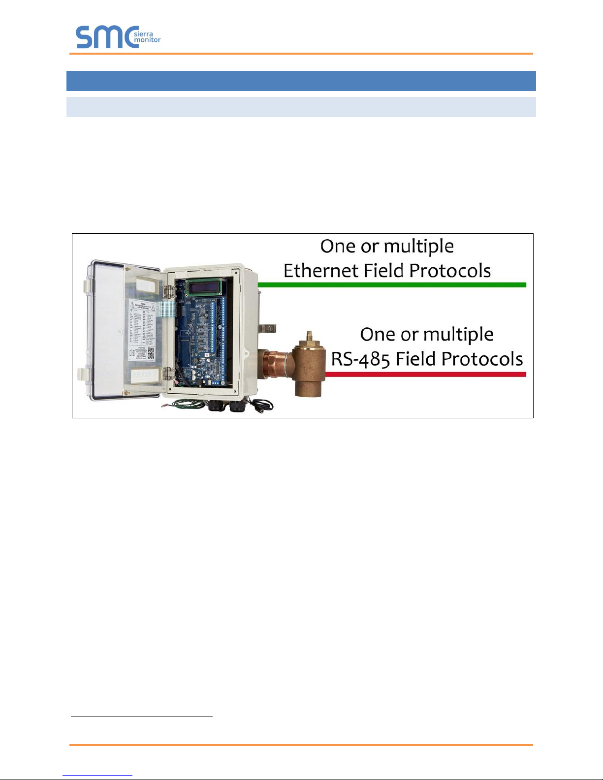
2.1 ProtoCessor Gateway
The ProtoCessor is an embedded module that is designed into Leonard Valve’s product (hereafter called
“device”) and is preconfigured to support BACnet MS/TP, BACnet/IP, Metasys
®
2
N2 by JCI, Modbus
TCP/IP, Modbus RTU or EtherNet/IP.
It is not necessary to download any configuration files to support the required applications. The
ProtoCessor is pre-loaded with all the tested Profiles/Configurations for the device to support the desired
protocols.
2
Metasys is a registered trademark of Johnson Controls Inc.
Leonard Valve ProtoCessor Start-up Guide
Page 8 of 32
3 SETUP FOR PROTOCESSOR
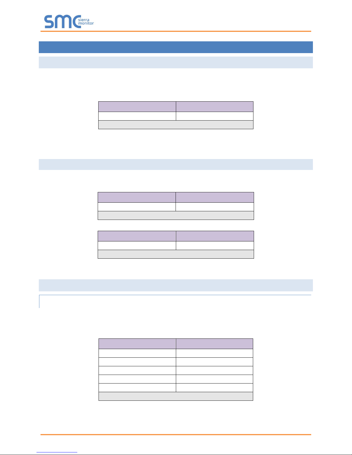
3.1 Record Identification Data
Each ProtoCessor has a unique part number located on the side or the back of the unit. This
number should be recorded, as it may be required for technical support. The numbers are as
follows:
Model
Part Number
ProtoCessor FPC-ED2
FPC-ED2-1145
Figure 1: ProtoCessor Part Numbers
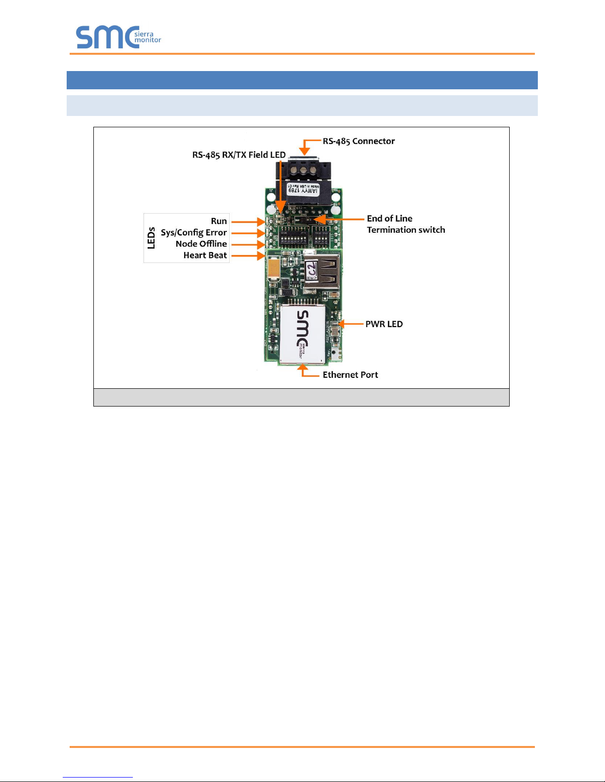
• FPC-ED2 units have the following 2 ports: RS-485 + Ethernet
3.2 Point Count Capacity and Registers per Device
The total number of Registers presented by the device attached to the ProtoCessor cannot
exceed:
Part number
Total Registers
FPC-ED2-1145
1,500
Figure 2: Supported Point Count Capacity
Devices
Registers Per Device
Valve
41
Figure 3: Registers per Device
3.3 Configuring Device Communications
3.3.1 Input COM Settings on the Device Connected to the ProtoCessor
• The connected serial device MUST have the same Baud Rate, Data Bits, Stop Bits, and
Parity settings as the ProtoCessor.
• Figure 4 specifies the device serial port settings required to communicate with the ProtoCessor.
Port Setting
Device
Protocol
PSP
Baud Rate
9600
Parity
None
Data Bits
8
Stop Bits
1
Figure 4: COM Settings
Leonard Valve ProtoCessor Start-up Guide
Page 9 of 32
4 INTERFACING PROTOCESSOR TO DEVICES
4.1 ProtoCessor FPC-ED2 Showing Connection Ports
Figure 5: ProtoCessor FPC-ED2
Leonard Valve ProtoCessor Start-up Guide
Page 10 of 32
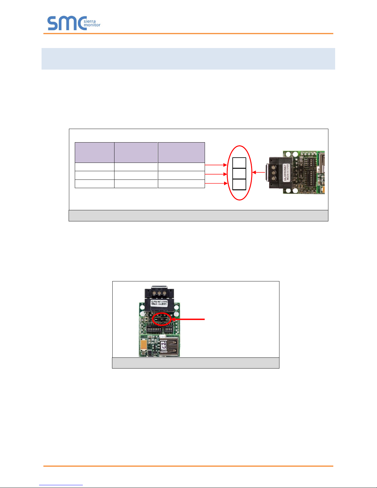
4.2 BACnet MS/TP, Modbus RTU, Metasys N2: Wiring Field Port to RS-485
Network
• Connect the BACnet MS/TP, Modbus RTU or Metasys N2 RS-485 network wires to the 3-pin RS-
485 connector on ProtoCessor ED2 as shown below in Figure 6.
o Use standard grounding principles for RS-485 GND
• See Section 5.5 for information on connecting to BACnet/IP and Modbus TCP/IP
network.
• If the ProtoCessor is the last device on the BACnet MS/TP, Modbus RTU or Metasys N2
trunk, then the End-Of-Line Termination Switch needs to be enabled (Figure 7).
o The default setting from the factory is OFF (switch position = right side)
o To enable the EOL Termination, turn the EOL switch ON (switch position = left
side)
BMS RS-
485 Wiring
ProtoCessor
Pin #
Pin
Assignment
RS-485 +
Pin 1
RS-485 +
RS-485 -
Pin 2
RS-485 -
-
Pin 3
RS-485 GND
Figure 7: RS-485 BMS Network EOL Switch
Figure 6: Connection from ProtoCessor to RS-485 Field Network
G
-
+
End-of-Line Switch
 Loading...