

SMC Networks ProtoAir FPA-W44 Startup Manual

Document Revision: 5.A
Auto Discovery/Web Configurator
Template Revision: 3
ProtoAir FPA-W44
Start-up Guide
For Interfacing Bosch Products:
C_Platform, D_Platform
To Building Automation Systems and SMC Cloud:
BACnet MS/TP, BACnet/IP, Modbus TCP/IP and Metasys N2
APPLICABILITY & EFFECTIVITY
Explains ProtoAir hardware and how to install it.
The instructions are effective for the above as of February 2019.

Bosch ProtoAir Start-up Guide
Page 2 of 63
Technical Support
Thank you for purchasing the ProtoAir for Bosch.
Please call Bosch for technical support of the ProtoAir product.
Sierra Monitor Corporation does not provide direct support. If Bosch needs to escalate the concern, they
will contact Sierra Monitor Corporation for assistance.
Support Contact Information:
Robert Bosch LLC
38000 Hills Tech Drive
Farmington Hills
Michigan 48331 USA
Customer Service:
(917) 421-7209
Contact via website: www.bosch.us/contact
Website: www.bosch.us

Bosch ProtoAir Start-up Guide
Page 3 of 63
Quick Start Guide
1. Methods of Configuration: (Section 2.2)
• Auto-Discovery: See Figure 1 for the table of devices that support automatic configuration.
• Web Configurator: For devices that cannot be automatically configured, use a web browser to
access the Web Configurator page.
2. Record the information about the unit. (Section 3.1)
3. Set COM settings for the device that will be connected to ProtoAir. (Section 3.3)
4. Connect the ProtoAir 3 pin RS-485 R1 port to the RS-485 network connected to each of the devices.
(Section 4.1)
5. Connect the ProtoAir 3 pin RS-485 R2 port to the field protocol cabling. (Section 4.2)
6. Connect power to ProtoAir’s 3 pin connector. (Section 4.5)
7. Connect a PC to the ProtoAir via Ethernet cable or by the ProtoAir’s Wi-Fi Access Point. (Section 5)
8. Auto-Discovery Devices: On the Web Configurator page, click the Discovery Mode button at the bottom
of the screen. It may take about 3 minutes for all the devices to be discovered and the configuration file
to be built. (Section 6.3)
9. Web Configuration Devices: Use a web browser to access the ProtoAir Web Configurator page to
select the profile of the device attached to the ProtoAir and enter any necessary device information.
Once the device is selected, the ProtoAir automatically builds and loads the appropriate configuration.
(Section 6.4)

Bosch ProtoAir Start-up Guide
Page 4 of 63
TABLE OF CONTENTS
1 Certification .......................................................................................................................................... 7
1.1 BTL Mark – BACnet® Testing Laboratory ....................................................................................... 7
2 Introduction .......................................................................................................................................... 8
2.1 ProtoAir Gateway ............................................................................................................................ 8
2.2 Methods of Configuration ............................................................................................................... 9
3 ProtoAir Setup .................................................................................................................................... 10
3.1 Record Identification Data ............................................................................................................ 10
3.2 Point Count Capacity and Registers per Device .......................................................................... 10
3.3 Configuring Modbus Device Communications ............................................................................. 11
3.3.1 Input COM Settings on Any Device Connected to the ProtoAir .............................................. 11
3.3.2 Set the Station Address for Any Device Attached to the ProtoAir .......................................... 11
3.4 Attaching the Antenna .................................................................................................................. 11
4 Interfacing ProtoAir to Devices ........................................................................................................ 12
4.1 Device Connections to ProtoAir .................................................................................................... 12
4.2 Wiring Field Port to RS-485 Serial Network ................................................................................. 12
4.3 Bias Resistors ............................................................................................................................... 13
4.4 Termination Resistor..................................................................................................................... 14
4.5 Power-Up ProtoAir ........................................................................................................................ 15
5 Connect the PC to the ProtoAir ........................................................................................................ 16
5.1 Connecting to the ProtoAir via Ethernet ....................................................................................... 16
5.1.1 Enable Access Through the Local Browser ............................................................................ 16
5.1.1.1 Changing the Subnet of the Connected PC .................................................................... 16
5.1.1.2 Changing the IP Address of the ProtoAir with FieldServer Toolbox ............................... 17
5.2 Connecting to the ProtoAir Over Wi-Fi Access Point ................................................................... 18
6 Configure the ProtoAir ...................................................................................................................... 19
6.1 Accessing the ProtoAir Web Configurator .................................................................................... 19
6.2 Select Field Protocol ..................................................................................................................... 21
6.3 Use Discovery Mode to Configure Devices Connected to the Gateway ...................................... 22
6.4 Setting ProtoAir Configuration Parameters .................................................................................. 23
6.4.1 Verify Device Communications ............................................................................................... 24
6.5 BACnet: Setting Node_Offset to Assign Specific Device Instances ............................................. 25
6.6 How to Start the Installation Over: Clearing Profiles .................................................................... 26
7 Network Settings................................................................................................................................ 27
7.1 Navigate to the FS-GUI Network Settings .................................................................................... 27
7.2 Change the ProtoAir IP Address .................................................................................................. 29
7.2.1 Update Wired Network Settings .............................................................................................. 30
7.2.2 Update Wi-Fi Client Settings ................................................................................................... 31
7.2.3 Common Settings .................................................................................................................... 32
8 SMC Cloud User Setup, Registration and Login ............................................................................ 33
8.1 User Setup .................................................................................................................................... 33
8.2 Registration Process..................................................................................................................... 35
8.3 Login to SMC Cloud...................................................................................................................... 39
Appendix A Troubleshooting ................................................................................................................... 41
Appendix A.1 Lost or Incorrect IP Address ............................................................................................. 41
Appendix A.2 Viewing Diagnostic Information ........................................................................................ 42
Appendix A.3 Checking Wiring and Settings ........................................................................................... 43
Appendix A.4 LED Diagnostics for Communications Between ProtoAir and Devices ............................ 44
Appendix A.5 Taking a FieldServer Diagnostic Capture ......................................................................... 45
Appendix A.5.1 Using the FieldServer Toolbox ................................................................................... 45
Appendix A.5.2 Using FS-GUI ............................................................................................................. 48
Appendix A.6 Wi-Fi Signal Strength ........................................................................................................ 49

Bosch ProtoAir Start-up Guide
Page 5 of 63
Appendix B Additional Information ......................................................................................................... 50
Appendix B.1 Updating Firmware ............................................................................................................ 50
Appendix B.2 BACnet: Setting Network_Number for More Than One ProtoAir on the Subnet .............. 50
Appendix B.3 Securing ProtoAir with Passwords .................................................................................... 51
Appendix B.4 Wi-Fi Access Point Network Settings ............................................................................... 52
Appendix B.5 Mounting ........................................................................................................................... 53
Appendix B.6 Physical Dimension Drawing ............................................................................................ 54
Appendix C Vendor Information – Bosch ............................................................................................... 55
Appendix C.1 C_Platform Modbus RTU Mappings to BACnet, Modbus TCP/IP and Metasys N2 ......... 55
Appendix C.2 D_Platform Modbus RTU Mappings to BACnet, Modbus TCP/IP and Metasys N2 ......... 57
Appendix D Reference .............................................................................................................................. 62
Appendix D.1 Specifications .................................................................................................................... 62
Appendix D.1.1 Compliance with UL Regulations ............................................................................... 62
Appendix E Limited 2 Year Warranty ...................................................................................................... 63

Bosch ProtoAir Start-up Guide
Page 6 of 63
LIST OF FIGURES
Figure 1: Method of Configuration for the Devices ....................................................................................... 9
Figure 2: ProtoAir Part Numbers ................................................................................................................. 10
Figure 3: Supported Point Count Capacity ................................................................................................. 10
Figure 4: Registers per Device ................................................................................................................... 10
Figure 5: COM Settings ............................................................................................................................... 11
Figure 6: RS-485 Connections from Devices to the ProtoAir ..................................................................... 12
Figure 7: Connection from ProtoAir to RS-485 Field Network .................................................................... 12
Figure 8: Bias Resistor DIP Switches ......................................................................................................... 13
Figure 9: Termination Resistor DIP Switch ................................................................................................. 14
Figure 10: Required Current Draw for the ProtoAir..................................................................................... 15
Figure 11: Power Connections .................................................................................................................... 15
Figure 12: Ethernet Port Location ............................................................................................................... 16
Figure 13: Web App Splash Page ............................................................................................................... 19
Figure 14: Login Window ............................................................................................................................ 19
Figure 15: Web App Landing Page ............................................................................................................. 20
Figure 16: Configure Tab ............................................................................................................................ 20
Figure 17: Web Configurator Showing Protocol Selector Parameter ......................................................... 21
Figure 18: Web Configurator Showing Discovery Mode Button ................................................................. 22
Figure 19: Web Configurator Showing Discovered Profiles ........................................................................ 22
Figure 20: Web Configurator Showing no Active Profiles ........................................................................... 23
Figure 21: Profile Selection Menu ............................................................................................................... 24
Figure 22: Web Configurator Showing Active Profile Additions .................................................................. 24
Figure 23: Web Configurator Node Offset Field.......................................................................................... 25
Figure 24: Active Profiles ............................................................................................................................ 25
Figure 25: Web App Landing Page ............................................................................................................. 27
Figure 26: Web Configurator Page – Diagnostics Button ........................................................................... 27
Figure 27: FS-GUI Landing Page ............................................................................................................... 28
Figure 28: Generic FS-GUI Navigation Panel – Network Settings ............................................................. 28
Figure 29: FS-GUI Ethernet Port Network Settings .................................................................................... 30
Figure 30: FS-GUI Wi-Fi Client Network Settings ....................................................................................... 31
Figure 31: FS-GUI Common Network Settings ........................................................................................... 32
Figure 32: Welcome to SMC Cloud Email .................................................................................................. 33
Figure 33: Setting User Details ................................................................................................................... 34
Figure 34: Web App Landing Page – SMC Cloud Tab ............................................................................... 35
Figure 35: Registration Information Page ................................................................................................... 35
Figure 36: SMC Cloud Connection Problems Message ............................................................................. 36
Figure 37: SMC Cloud Registration Page ................................................................................................... 37
Figure 38: Device Registered for SMC Cloud ............................................................................................. 38
Figure 39: SMC Cloud Login Page ............................................................................................................. 39
Figure 40: SMC Cloud Privacy Policy ......................................................................................................... 39
Figure 41: SMC Cloud Landing Page ......................................................................................................... 40
Figure 42: Ethernet Port Location ............................................................................................................... 41
Figure 43: Error Messages Screen ............................................................................................................. 42
Figure 44: Diagnostic LEDs ........................................................................................................................ 44
Figure 45: Ethernet Port Location ............................................................................................................... 45
Figure 46: Wi-Fi Signal Strength Listing ..................................................................................................... 49
Figure 47: Web Configurator – Network Number Field ............................................................................... 50
Figure 48: FS-GUI Passwords Page ........................................................................................................... 51
Figure 49: Password Recovery Page ......................................................................................................... 51
Figure 50: FS-GUI Wi-Fi AP Network Settings ........................................................................................... 52
Figure 51: DIN Rail ...................................................................................................................................... 53
Figure 52: ProtoAir FPA-W44 Dimensions ................................................................................................. 54
Figure 53: Specifications ............................................................................................................................. 62

Bosch ProtoAir Start-up Guide
Page 7 of 63
1 CERTIFICATION
1.1 BTL Mark – BACnet
®
1
Testing Laboratory
1
BACnet is a registered trademark of ASHRAE
The BTL Mark on ProtoAir is a symbol that indicates that a product has
passed a series of rigorous tests conducted by an independent laboratory
which verifies that the product correctly implements the BACnet features
claimed in the listing. The mark is a symbol of a high-quality BACnet product.
Go to www.BACnetInternational.net for more information about the BACnet
Testing Laboratory. Click here for the BACnet PIC Statement.
Bosch ProtoAir Start-up Guide
Page 8 of 63
2 INTRODUCTION
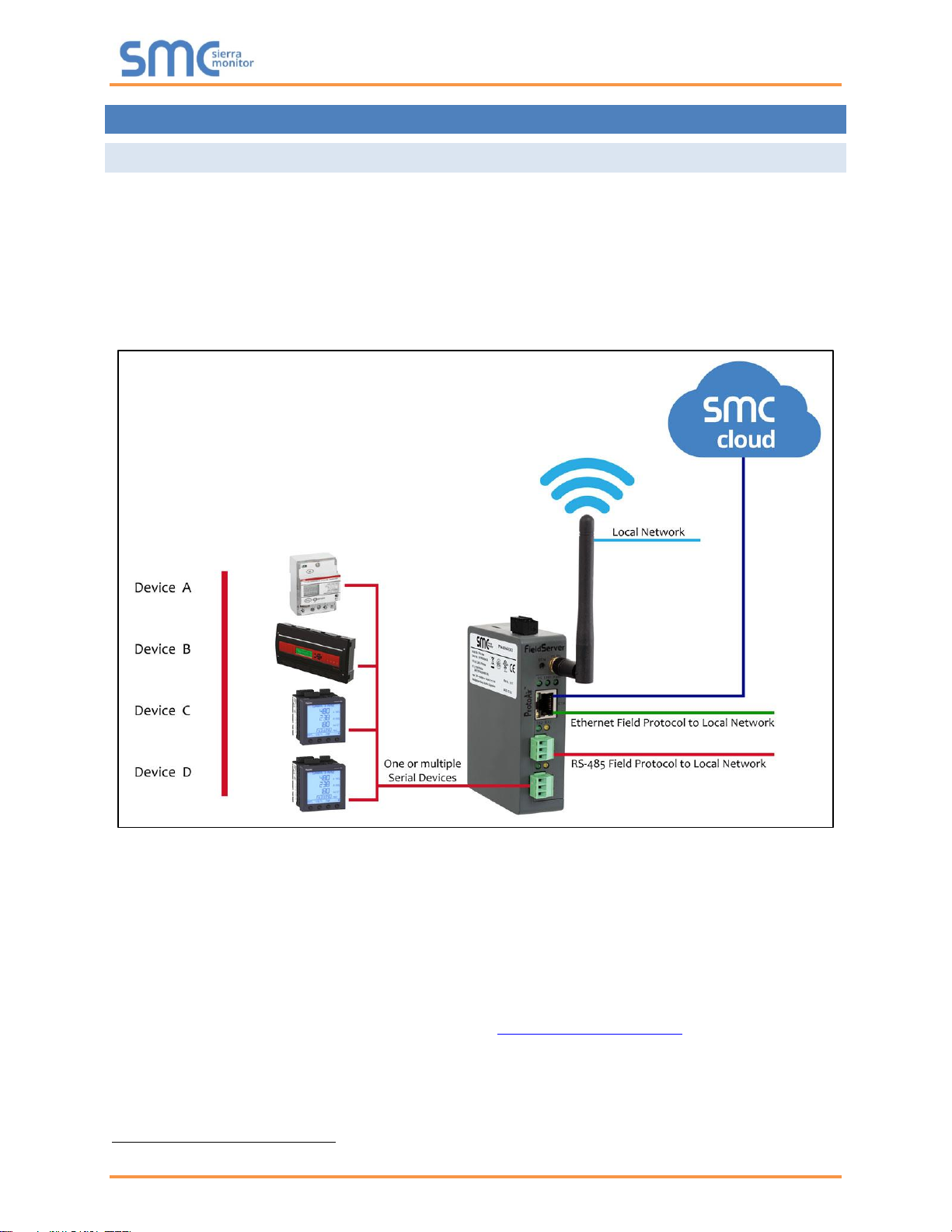
2.1 ProtoAir Gateway
The ProtoAir wireless gateway is an external, high performance building automation multi-protocol
gateway that is preconfigured to automatically communicate between Bosch’s devices (hereafter simply
called “device”) connected to the ProtoAir and automatically configures them for BACnet/IP, BACnet
MS/TP, Modbus TCP/IP and Metasys
®
2
N2.
It is not necessary to download any configuration files to support the required applications. The ProtoAir is
pre-loaded with tested profiles/configurations for the supported devices.
FPA-W44 Connectivity Diagram:
The ProtoAir can connect with Sierra Monitor’s SMC Cloud. The SMC Cloud allows technicians, the OEM's
support team and Sierra Monitor's support team to remotely connect to the ProtoAir. The SMC Cloud
provides the following capabilities for any registered devices in the field:
• Remotely monitor and control devices.
• Collect device data and view it on the SMC Cloud Dashboard and the SMC Smart Phone App.
• Create user defined device notifications (alarm, trouble and warning) via SMS and/or Email.
• Generate diagnostic captures (as needed for troubleshooting) without going to the site.
For more information about the SMC Cloud, refer to the SMC Cloud Start-up Guide.
2
Metasys is a registered trademark of Johnson Controls Inc.
Bosch ProtoAir Start-up Guide
Page 9 of 63
2.2 Methods of Configuration
The ProtoAir offers two methods of configuration:
• Auto-Discovery: Supported RS-485 devices can be automatically detected and identified for
addition to the ProtoAir’s configuration via the ProtoAir’s Web Configurator. (Section 6.3)
• Web Configurator: Devices that cannot be identified by Auto-Discovery must be configured to the
gateway by selecting profiles on the ProtoAir’s Web Configurator. The Web Configurator shows all
the stored profiles/devices on the ProtoAir. It will also show all the devices that were previously
discovered or selected. To configure, select a device and enter the Station Address. Once all
required device profiles are saved, the ProtoAir automatically builds and downloads the
configuration for the desired protocol. (Section 6.4)
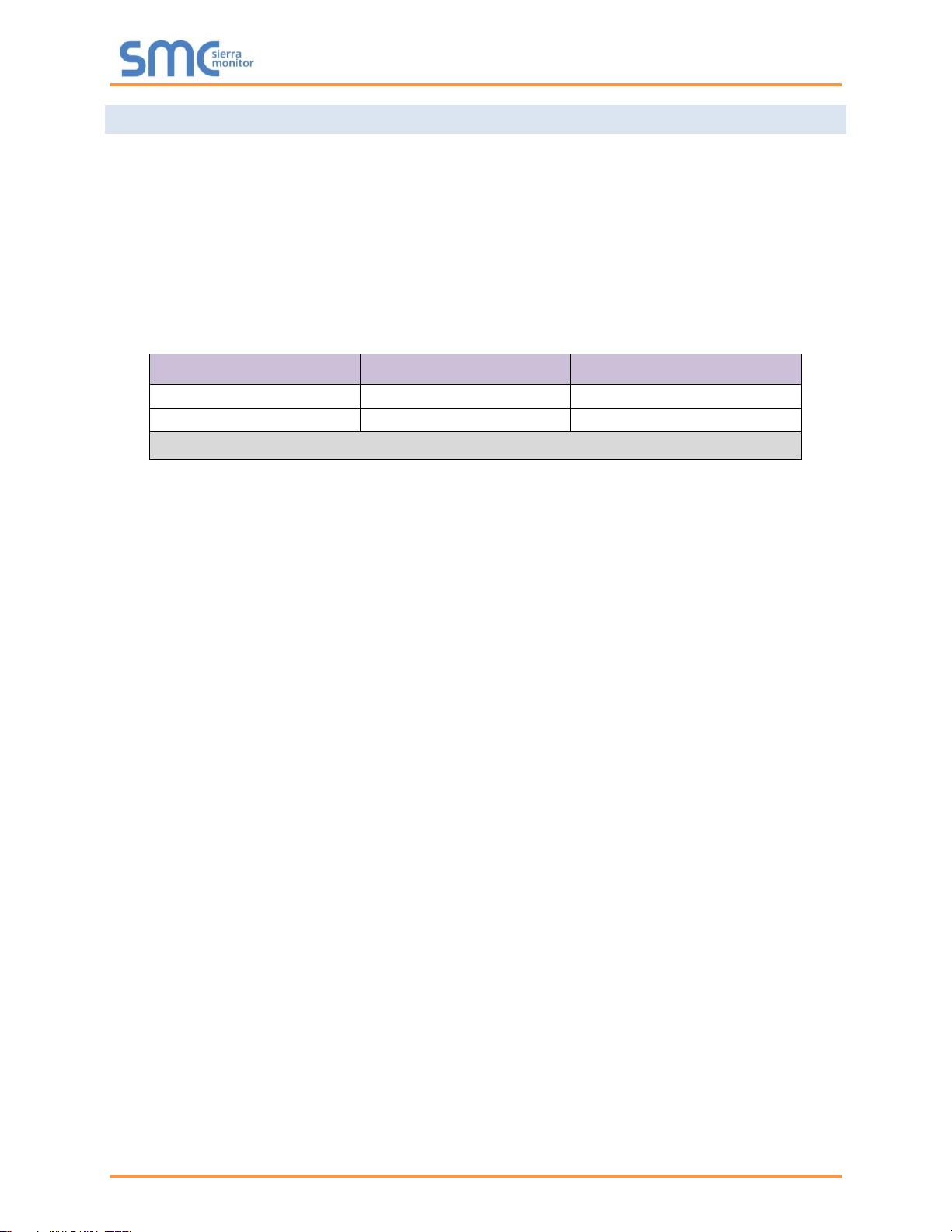
Devices
Type of Communication
Type of Configuration
C_Platform
Modbus RTU
Auto-Discovery
D_Platform (1 - 8 boilers)
Modbus RTU
Web-Configurator
Figure 1: Method of Configuration for the Devices
Bosch ProtoAir Start-up Guide
Page 10 of 63
3 PROTOAIR SETUP
3.1 Record Identification Data
Each ProtoAir has a unique part number located on the side or the back of the unit. This number should be
recorded, as it may be required for technical support. The numbers are as follows:
Model
Part Number
ProtoAir
FPA-W44-1726
Figure 2: ProtoAir Part Numbers
• FPA-W44 units have the following 3 ports: RS-485 + Ethernet + RS-485
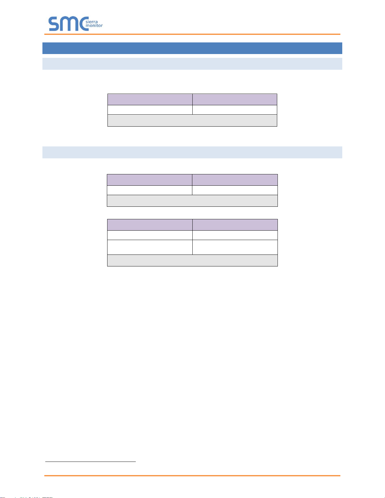
3.2 Point Count Capacity and Registers per Device
The total number of registers presented the device(s) attached to the ProtoAir cannot exceed:
Part number
Total Registers
FPA-W44-1726
1,500
Figure 3: Supported Point Count Capacity
Devices
Registers Per Device
C_Platform
154
D_Platform (1 - 8 boilers)3
30 - 54 - 78 - 102 - 126 -
150 - 174 - 198
Figure 4: Registers per Device
3
The numbers in the D_Platform Registers column are for 1 boiler, 2 boilers, 3 boilers, etc.

Bosch ProtoAir Start-up Guide
Page 11 of 63
3.3 Configuring Modbus Device Communications
3.3.1 Input COM Settings on Any Device Connected to the ProtoAir
• Any connected serial device MUST have the same baud rate, data bits, stop bits, and
parity settings as the ProtoAir.
• Figure 5 specifies the device serial port settings required to communicate with the ProtoAir.
Port Setting
Device
Protocol
Modbus RTU
Baud Rate
9600
Parity
None
Data Bits
8
Stop Bits
2
Figure 5: COM Settings
3.3.2 Set the Station Address for Any Device Attached to the ProtoAir
• Set the Station Address for the device attached to ProtoAir. The Station Address needs to be
uniquely assigned between 1 and 255.
• Document the Station Address that is assigned. The Station Address assigned is used for
deriving the Device Instance for BACnet/IP and BACnet MS/TP (Section 6.5)
NOTE: The Metasys N2 and Modbus TCP/IP field protocol Station Addresses are automatically set
to be the same value as the Station Address of the device.
3.4 Attaching the Antenna
Wi-Fi Antenna:
Screw in the Wi-Fi antenna to the front of the unit as shown in Figure 52.
NOTE: Using an external antenna is also an option. An external antenna can be plugged into the
SMA connector. The best antenna for the job depends on the range, topography and
obstacles between the two radios.
Bosch ProtoAir Start-up Guide
Page 12 of 63
4 INTERFACING PROTOAIR TO DEVICES
4.1 Device Connections to ProtoAir
The ProtoAir has a 3-pin Phoenix connector for connecting RS-485 devices on the R1 port.
NOTE: Use standard grounding principles for RS-485 GND.
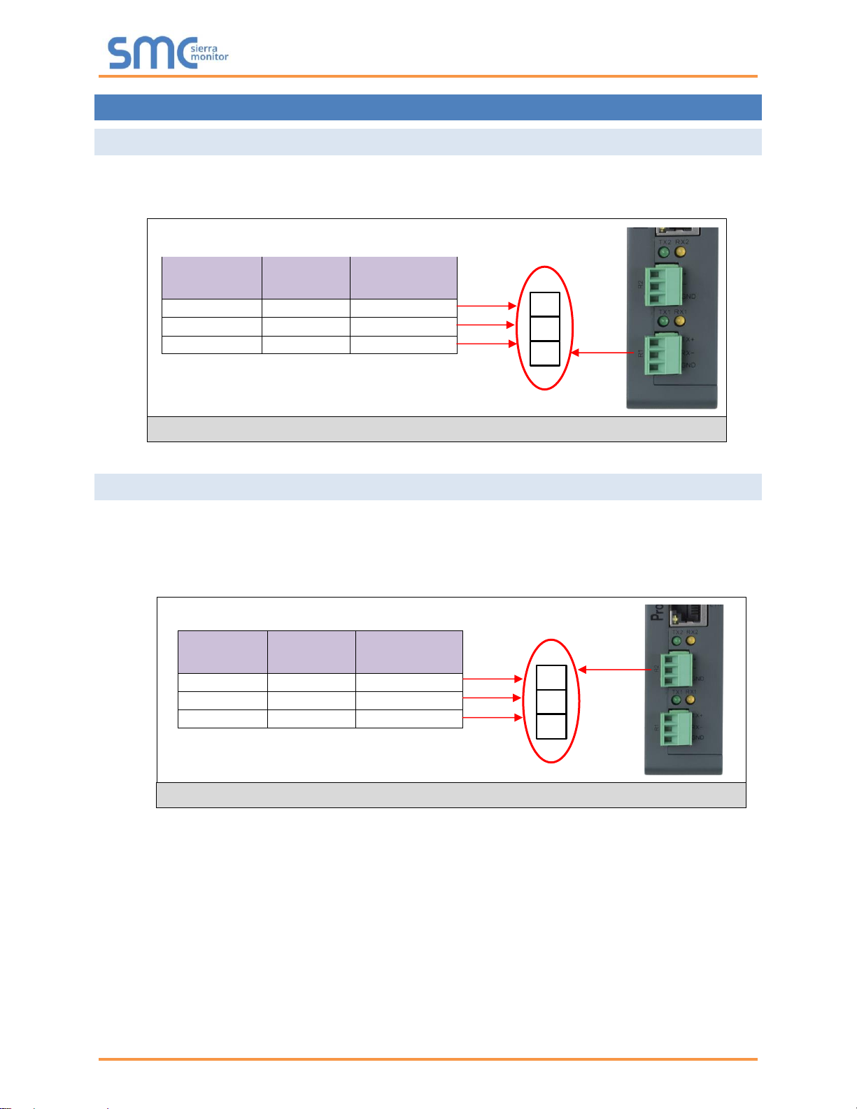
4.2 Wiring Field Port to RS-485 Serial Network
• Connect the RS-485 network wires to the 3-pin RS-485 connector on the R2 port. (Figure 7)
o Use standard grounding principles for RS-485 GND
• See Section 5 for information on connecting to an Ethernet network.
Device Pins
ProtoAir
Pin #
Pin
Assignment
RS-485 +
Pin 1
RS-485 +
RS-485 -
Pin 2
RS-485 -
RS-485 GND
Pin 3
RS-485 GND
BMS
Wiring
ProtoAir
Pin #
Pin
Assignment
RS-485 +
Pin 1
RS-485 +
RS-485 -
Pin 2
RS-485 -
-
Pin 3
RS-485 GND
Figure 7: Connection from ProtoAir to RS-485 Field Network
G
-
Figure 6: RS-485 Connections from Devices to the ProtoAir
G
-
+
Bosch ProtoAir Start-up Guide
Page 13 of 63
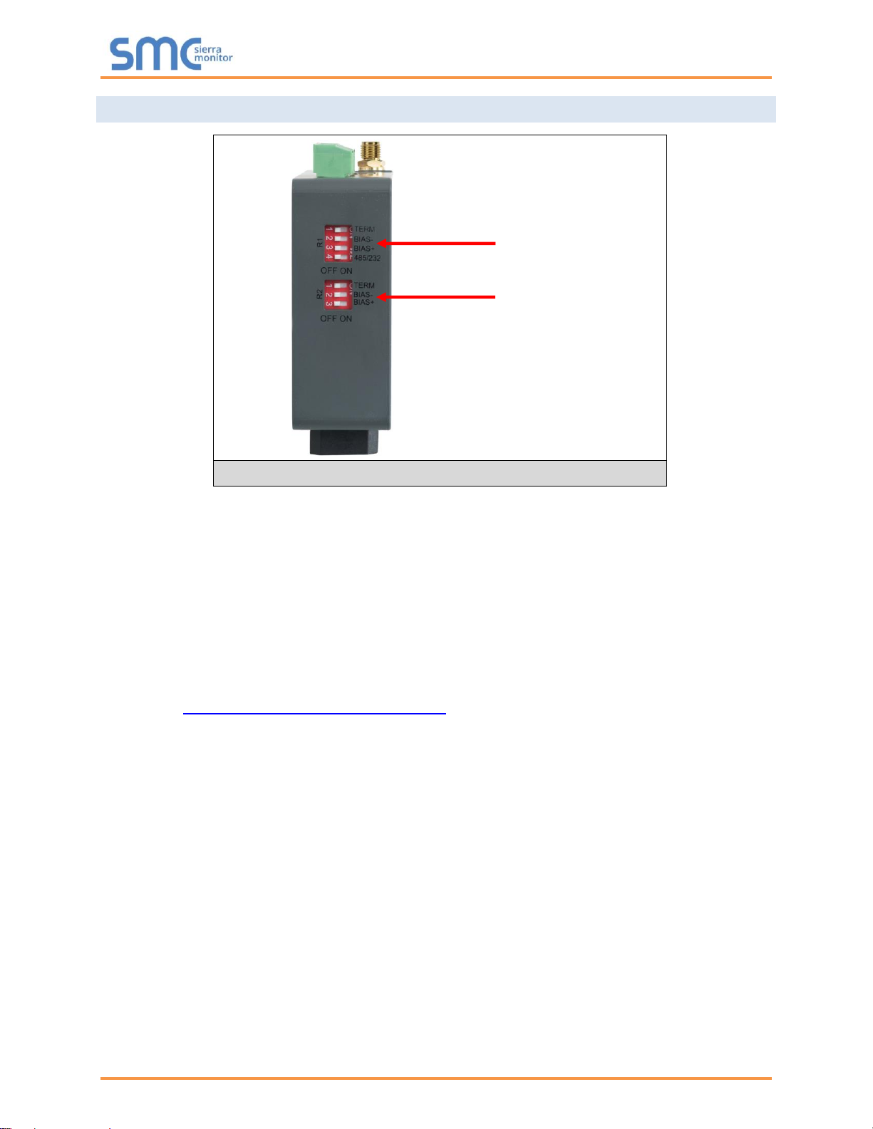
4.3 Bias Resistors
To enable Bias Resistors, move both the BIAS- and BIAS+ dip switches to the right as shown in
Figure 8.
The ProtoAir bias resistors are used to keep the RS-485 bus to a known state, when there is no
transmission on the line (bus is idling), to help prevent false bits of data from being detected. The bias
resistors typically pull one line high and the other low - far away from the decision point of the logic.
The bias resistor is 510 ohms which is in line with the BACnet spec. It should only be enabled at one
point on the bus (for example, on the field port were there are very weak bias resistors of 100k). Since
there are no jumpers, many gateways can be put on the network without running into the bias resistor
limit which is < 500 ohms.
NOTE: See www.ni.com/support/serial/resinfo.htm for additional pictures and notes.
NOTE: The R1 and R2 DIP Switches apply settings to the respective serial port.
NOTE: If the gateway is already powered on, DIP switch settings will not take effect unless the
unit is power cycled.
R1 Bias Resistor DIP
Switches (2 and 3)
Figure 8: Bias Resistor DIP Switches
R2 Bias Resistor DIP
Switches (2 and 3)
Bosch ProtoAir Start-up Guide
Page 14 of 63
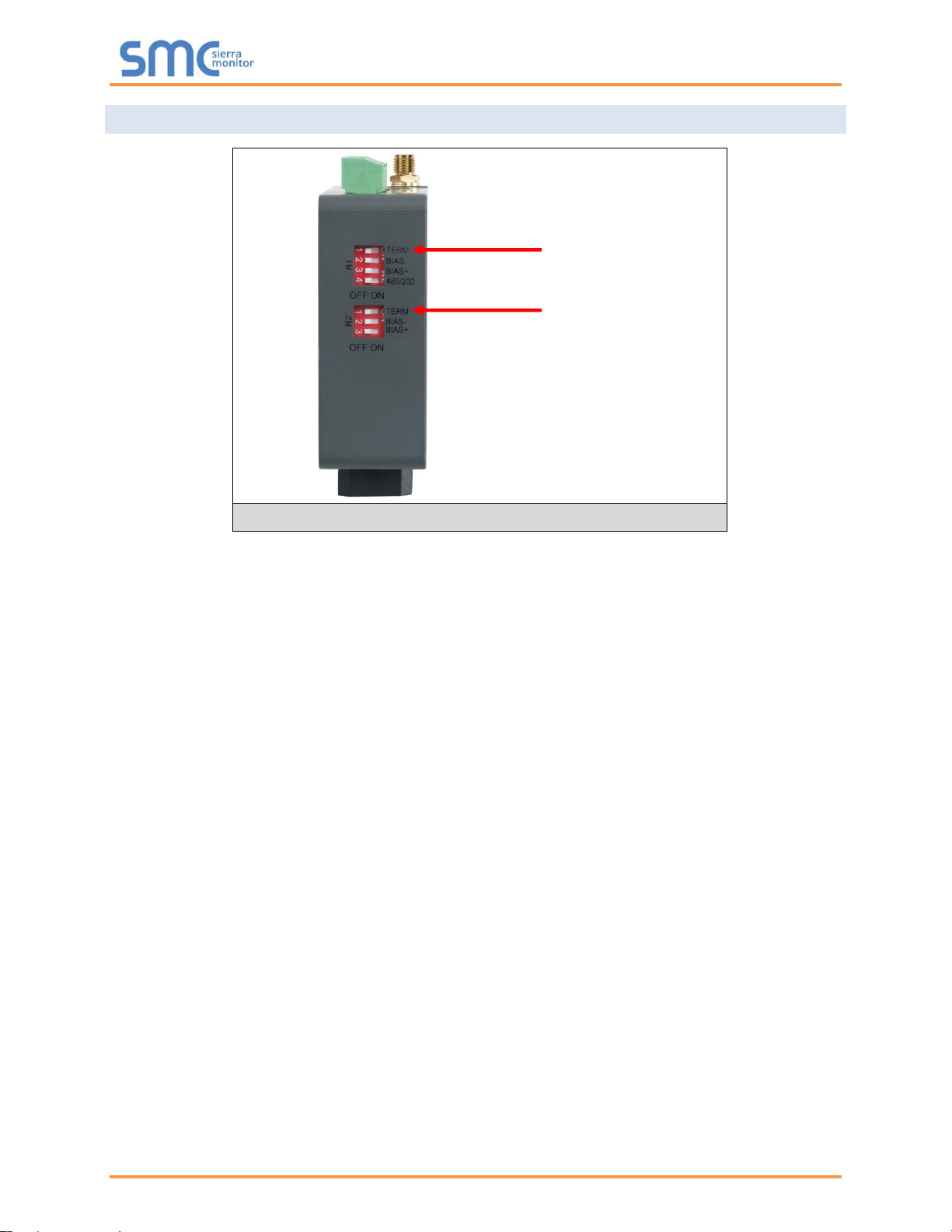
4.4 Termination Resistor
If the ProtoAir is the last device on the serial trunk, then the End-Of-Line Termination Switch needs to be
enabled. To enable the Termination Resistor, move the TERM dip switch to the right as shown in
Figure 9.
Termination resistor is also used to reduce noise. It pulls the two lines of an idle bus together. However,
the resistor would override the effect of any bias resistors if connected.
NOTE: The R1 and R2 DIP Switches apply settings to the respective serial port.
NOTE: If the gateway is already powered on, DIP switch settings will not take effect unless the
unit is power cycled.
R1 Termination
Resistor DIP Switch (1)
Figure 9: Termination Resistor DIP Switch
R2 Termination
Resistor DIP Switch (1)
Bosch ProtoAir Start-up Guide
Page 15 of 63
4.5 Power-Up ProtoAir
Check power requirements in the table below:
Power Requirement for ProtoAir External Gateway
Current Draw Type
ProtoAir Family
12VDC
24V DC/AC
FPA – W44 (Typical)
250mA
125mA
NOTE: These values are ‘nominal’ and a safety margin should be added to the power supply of
the host system. A safety margin of 25% is recommended.
Figure 10: Required Current Draw for the ProtoAir
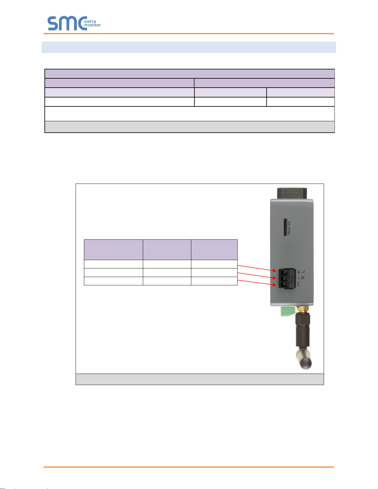
Apply power to the ProtoAir as shown below in Figure 11. Ensure that the power supply used complies
with the specifications provided in Appendix D.1.
• The ProtoAir accepts 12-24VDC or 24VAC on pins 4 and 5.
• Frame GND should be connected.
Power to
ProtoAir
ProtoAir
Pin #
Pin
Assignment
Power In (+)
Pin 4
V +
Power In (-)
Pin 5
V -
Frame Ground
Pin 6
FRAME GND
Figure 11: Power Connections
Bosch ProtoAir Start-up Guide
Page 16 of 63
5 CONNECT THE PC TO THE PROTOAIR
There are two ways to connect the PC to the ProtoAir, either by Ethernet cable (Section 5.1) or Wi-Fi
Access Point (Section 5.2).
5.1 Connecting to the ProtoAir via Ethernet
First, connect a Cat-5 Ethernet cable (straight through or cross-over) between the local PC and ProtoAir.
5.1.1 Enable Access Through the Local Browser
There are two methods to enable access to the ProtoAir in the local browser, either by changing the
subnet of the connected PC (Section 5.1.1.1) or using the FieldServer Toolbox to change the IP
Address of the ProtoAir (Section 5.1.1.2).
NOTE: Only perform one method or the other.
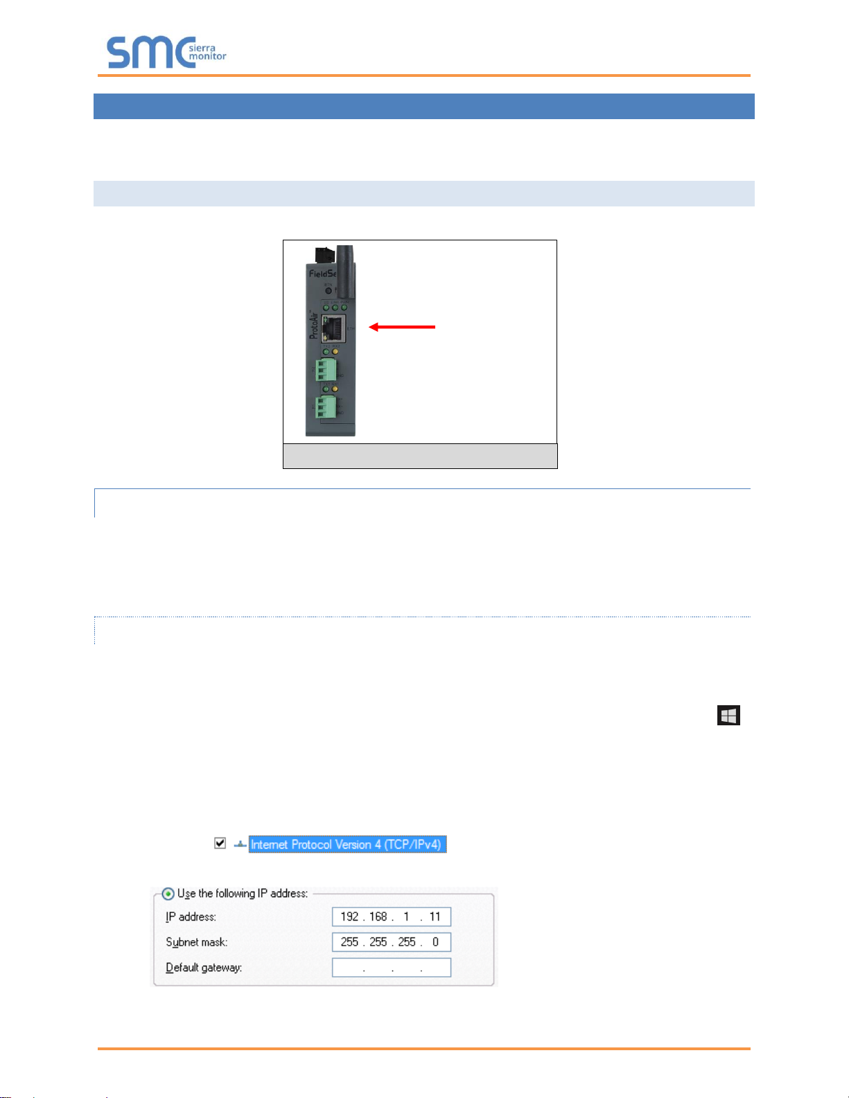
5.1.1.1 Changing the Subnet of the Connected PC
The default IP Address for the ProtoAir is 192.168.1.24, Subnet Mask is 255.255.255.0. If the PC and
ProtoAir are on different IP networks, assign a static IP Address to the PC on the 192.168.1.xxx network.
For Windows 10:
• Find the search field in the local computer’s taskbar (usually to the right of the windows icon )
and type in “Control Panel”.
• Click “Control Panel”, click “Network and Internet” and then click “Network and Sharing Center”.
• Click “Change adapter settings” on the left side of the window.
• Right-click on “Local Area Connection” and select “Properties” from the dropdown menu.
• Highlight and then click the Properties button.
• Select and enter a static IP Address on the same subnet. For example:
• Click the Okay button to close the Internet Protocol window and the Close button to close the
Ethernet Properties window.
Ethernet Port
Figure 12: Ethernet Port Location
Bosch ProtoAir Start-up Guide
Page 17 of 63
5.1.1.2 Changing the IP Address of the ProtoAir with FieldServer Toolbox
• Ensure that FieldServer Toolbox is loaded onto the local PC. Otherwise, download the
FieldServer-Toolbox.zip via the Sierra Monitor website’s Software Downloads.
• Extract the executable file and complete the installation.
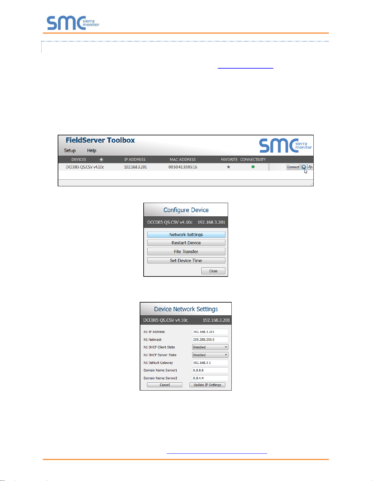
• Double click on the FS Toolbox Utility and click Discover Now on the splash page.
• Find the desired gateway and click the Configure Device button (gear icon) to the right of the
gateway information.
NOTE: If connectivity status is green, then the IP Address doesn’t need to be changed (the
ProtoAir is already on the same subnet). Skip the rest of the section and go to Section 6.
• Select Network Settings in the Configure Device window.
• Modify the IP Address (N1 IP Address field) of the gateway Ethernet port.
o Change additional fields as needed
NOTE: If the gateway is connected to a router, the Default Gateway field of the gateway should be
set to the IP Address of the connected router.
NOTE: Do not change the DHCP Server State (N1 DHCP Server State field).
NOTE: If DNS settings are unknown, set DNS1 to “8.8.8.8” and DNS2 to “8.8.4.4”.
• Click Update IP Settings, then click the “Change and restart” button to reboot the Gateway and
activate the new IP Address. See the FieldServer Toolbox and GUI Manual for more information.
Bosch ProtoAir Start-up Guide
Page 18 of 63
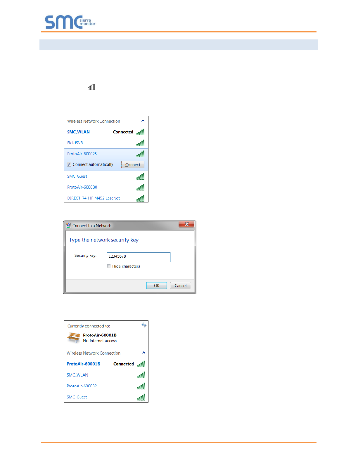
5.2 Connecting to the ProtoAir Over Wi-Fi Access Point
When the ProtoAir is first powered up, the Wi-Fi Access Point will be enabled allowing direct connection
to the ProtoAir with Wi-Fi.
To connect to the ProtoAir Wi-Fi Access Point:
• Click the icon (found in the bottom-right corner of the computer screen) to open the available
Wireless Network Connections.
• Select the desired ProtoAir and click Connect.
• Enter the Security key. The default is 12345678.
The available Wireless Network Connection menu should now show that the computer is connected to
the ProtoAir.

Bosch ProtoAir Start-up Guide
Page 19 of 63
6 CONFIGURE THE PROTOAIR
6.1 Accessing the ProtoAir Web Configurator
• Navigate to the IP Address of the ProtoAir on the local PC using one of two methods:
o Open a web browser and enter the IP Address of the ProtoAir; the default Ethernet address is
192.168.1.24, the default Wi-Fi Access Point address is 192.168.50.1
o If using the FieldServer Toolbox (Section 5.1.1.2), click the Connect button
NOTE: If the IP Address of the ProtoAir has been changed, the IP Address can be discovered
using the FS Toolbox utility. See Appendix A.1 for instructions.
• Once at the Web App splash page, click the Login button.
• Enter the previously set up or default username and password.
NOTE: The default username is “admin”. The default password is “admin”.
Figure 14: Login Window
Figure 13: Web App Splash Page
 Loading...