

SMC Networks PPA100 Series,PPA101 Series,PPA102 Series Instruction Manual
PPA-SMW22EN
Model
PPA100 for
high pressure
PPA101 for
vacuum
PPA102 for
low pressure
Rated pressure
range
–0.1 to 1 MPa
–101 to 10 kPa
–10 to 100 kPa
Display method
3 digit LCD back light
Pressure display
discrimination
1/100
Min.
display
units
1
kPa — 1
1
MPa
0.01 — —
mmHg — 5
—
kgf/cm2
0.1
0.01
0.01
inHg — 0.2
—
psi 1 0.1
0.1
bar
0.1
0.01
0.01
Error display
Over pressure, Memory data error, Change battery sign
Function
Peak/bottom display, Backlight, Auto power OFF
Zero clear, Units display switching
Withstanding
pressure
1.5 MPa
200 kPa
200 kPa
Applicable fluid
Air, Non-corrosive gases, Nonflammable gas
Power supply
voltage
3 VDC, Type AA dry cell x 2 pcs.
Battery life
12 months continuous operation
(Without backlighting, temperature conditions: at 25°C)
Response speed
250 ms
Display accuracy
±2% F.S. (Temperature conditions: at 25°C)
2
Repeatability
±1% F.S. (Temperature conditions: at 25°C)
Temperature
characteristics
±3% F.S. (0 to 50°C with 25°C standard)
Connection port
size
M5 x 0.8
Operating
temperature range
0 to 50°C (With no condensation)
Operating
humidity range
35 to 85% RH (With no condensation)
Enclosure
IP40
Weight
Approx. 100 g (Unit 50 g, batteries 50 g)
Standard
CE marked (EMC directive/RoHS directive)
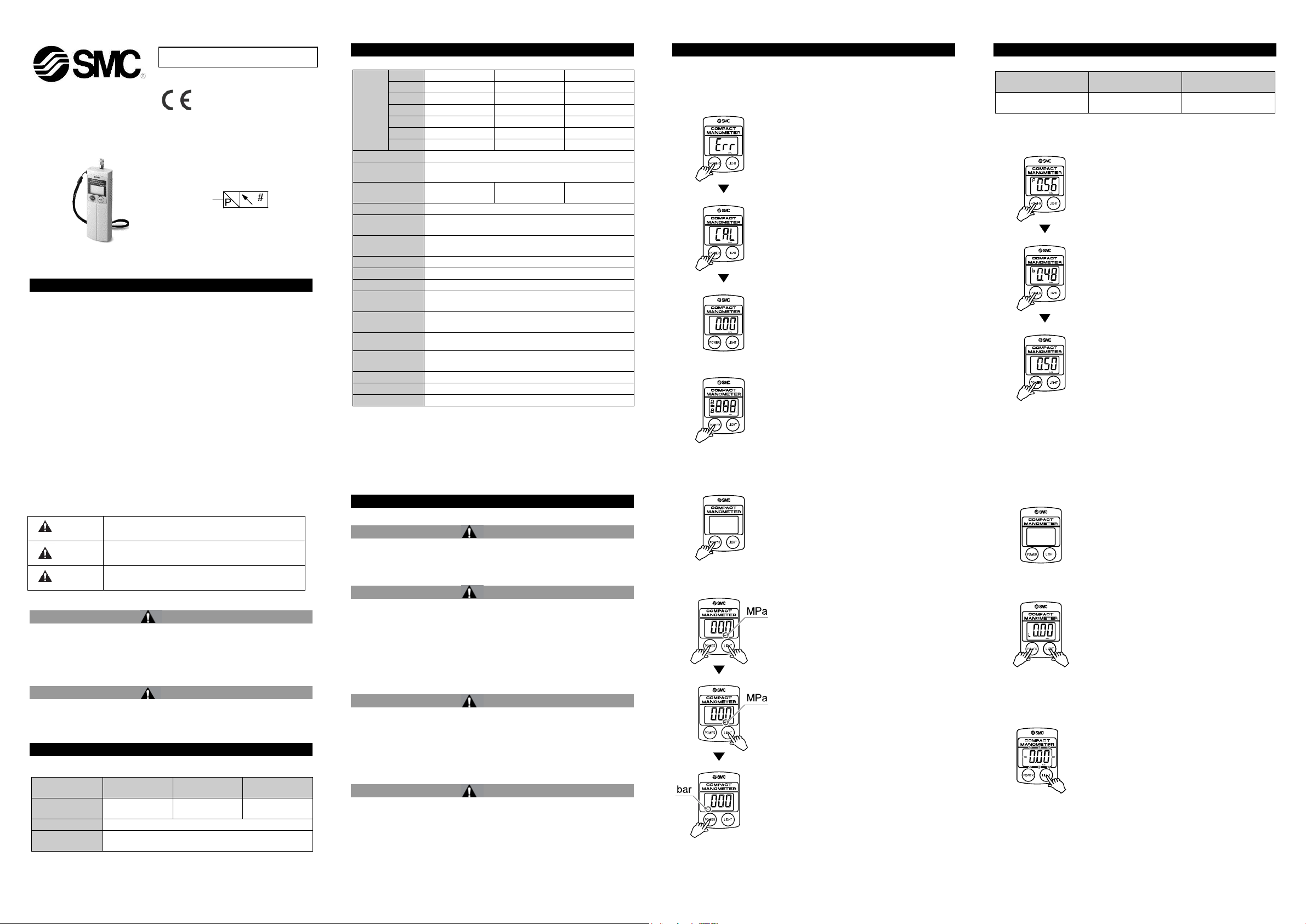
1. Confirmation of display.
When power is applied, if there is nothing on
the LCD display, proceed to step 2.
If "Err" is displayed on the LCD, switch the
power off and on again. Then the display
should be clear.
Proceed to step 2.
2. Press and hold the POWER button for
6 seconds or more.
Press and hold for 6 seconds or more. The
unit will go into zero clear. When this
happens "CAL" will appear on the LCD.
3. Release the POWER button.
When zero clear is finished, the unit can be
operated.
Press the POWER button.
•The power comes ON when it is pressed.
•When pressed and held for 6 seconds or
more, the unit goes into zero clear.
Press and hold the POWER button for 3
seconds or more.
•When pressed and held for 3 seconds or
more, the power turns OFF.
•When there is no button operation for more
than 5 minutes, the power turns OFF. (auto
power OFF function)
1. Press and hold the POWER and LIGHT
buttons for 3 seconds or more.
When pressed continuously for 3 seconds or
more, the units on the LCD will flash.
2. Press the LIGHT button.
The units will change.
(See the table below.)
3. Press the POWER button.
The units are set, and the unit display
switching is completed.
High pressure
(PPA100)
Vacuum
(PPA101)
Low pressure
(PPA102)
MPa → bar → psi → kgf
kPa → bar → psi → inHg
→ mmHg
kPa → bar → psi → kgf
Press the POWER button.
•Peak display
Displays the maximum pressure value and
"P" appears on the LCD. The display will
change if pressure increases beyond the
pressure value that is being held.
Press the POWER button.
•Bottom display
Displays the minimum pressure value and
"b" appears on the LCD. The display will
change if pressure falls below the pressure
value that is being held.
(These modes are useful for confirming
pressure fluctuations.)
Press the POWER button.
When the power is turned ON and there is
no button operation for more than 5 minutes,
the power will turn OFF.
: For cancelling this function, refer to the operation
of the lock mode (below).
Press and hold the POWER and LIGHT
buttons for 6 seconds or more.
The auto power OFF function is cancelled by
activating the lock mode (auto power OFF
cancel).
When continuously pressed for 6 seconds or
more, "L" is displayed on the LCD.
When the power is turned OFF, the lock
mode is released.
Press the LIGHT button.
The display lights up while the button is
being pressed. In the lock mode, it lights up
when pressed and turns off when pressed
again.
However, the maximum lighting time is
approximately one minute.
Caution
Caution indicates a hazard with a low level of risk which, if
not avoided, could result in minor or moderate injury.
Warning
Warning indicates a hazard with a medium level of risk
which, if not avoided, could result in death or serious injury.
Danger
Danger indicates a hazard with a high level of risk which, if
not avoided, will result in death or serious injury.
ORIGINAL INSTRUCTIONS
Refer to Declaration of
Directives
Conformity for relevant
Instruction Manual
Compact Manometer
Series PPA100/PPA101/PPA102
The intended use of this product is pressure measurement.
1 Safety Instructions
These safety instructions are intended to prevent hazardous situations
and/or equipment damage. These instructions indicate the level of
potential hazard with the labels of “Caution,” “Warning” or “Danger.”
They are all important notes for safety and must be followed in addition
to International Standards (ISO/IEC)
*1)
ISO 4414: Pneumatic fluid power - General rules relating to systems.
ISO 4413: Hydraulic fluid power - General rules relating to systems.
IEC 60204-1: Safety of machinery - Electrical equipment of machines.
(Part 1: General requirements)
ISO 10218-1: Manipulating industrial robots -Safety. etc.
Refer to product catalogue, Operation Manual and Handling
Precautions for SMC Products for additional information.
Keep this manual in a safe place for future reference.
*1)
, and other safety regulations.
2 Specifications - continued
: 2 pcs. of type AA dry batteries (manganese R6 or alkaline LR6) are not
included.
1: For the unit switching function (Types without the unit switching function is
fixed in SI unit (kPa or MPa)).
2: In regards to the compatibility condition of the EMC directives, the pressure
display value variation is ±15% F.S. or less.
4 Settings
Operation and Functions
• Initial Setting
Be certain to perform initial setting when using for the first time and after
changing batteries, as the unit will indicate memory data error.
• Power ON
4 Settings - continued
: The "inHg" unit cannot be displayed.
• Peak/Bottom Display
Do this when pressure is being displayed.
: Since this is combined with power OFF operation, the button should be
released at the point when "P" or "b" is displayed.
Warning
Always ensure compliance with relevant safety laws and
standards.
All work must be carried out in a safe manner by a qualified person in
compliance with applicable national regulations.
Caution
The product is provided for use in manufacturing industries.
This product may cause interference if used in residential premises.
2 Specifications
3 Installation
3.1 Installation
Warning
Do not install the product unless the safety instructions have been read
and understood.
3.2 Environment
Warning
Do not use in an environment where corrosive gases, chemicals, salt
water or steam are present.
Do not use in an explosive atmosphere.
Do not expose to direct sunlight. Use a suitable protective cover.
Do not install in a location subject to vibration or impact. Check the
product specifications.
Do not mount in a location exposed to radiant heat.
3.3 Piping
Caution
Before piping make sure to clean up chips, cutting oil, dust etc.
When installing piping or fittings, ensure sealant material does not
enter inside the port. When using seal tape, leave 1 thread exposed
on the end of the pipe/fitting.
Tighten fittings to the specified tightening torque.
3.4 Lubrication
Caution
SMC products have been lubricated for life at manufacture, and do
not require lubrication in service.
If a lubricant is used in the system, refer to catalogue for details.
• Power OFF
• Unit Display Switching
: This operation cannot be done for the type which does not have the unit
switching function.
• Auto Power OFF Function
• Lock Mode (Auto power OFF cancel)
• Turning on the Backlight
Page 1 of 2
PPA-SMW22EN
Press the POWER button for 6 seconds
or more.
The zero point displayed at atmospheric
pressure can be automatically adjusted. This
means it is possible to eliminate a display
discrepancy at atmospheric pressure.
•Turn the power OFF.
•Release the supply pressure to the
atmosphere.
•When continuously pressed for 6 seconds
or more, zero clear is performed and "CAL"
is displayed on the LCD.
URL :
http// www.smcworld.com (Global) http// www.smceu.com (Europe)
4 Settings - continued
•Zero Clear
5 How to Order
Refer to catalogue for ‘How to Order’.
6 Outline Dimensions (mm)
Refer to catalogue for outline dimensions.
7 Maintenance
7.1 General Maintenance
Caution
Not following proper maintenance procedures could cause the
product to malfunction and lead to equipment damage.
If handled improperly, compressed air can be dangerous.
Maintenance of pneumatic systems should be performed only by
qualified personnel.
Before performing maintenance, turn off the power supply and be
sure to cut off the supply pressure. Confirm that the air is released to
atmosphere.
After installation and maintenance, apply operating pressure and
power to the equipment and perform appropriate functional and
leakage tests to make sure the equipment is installed correctly.
If any electrical connections are disturbed during maintenance,
ensure they are reconnected correctly and safety checks are carried
out as required to ensure continued compliance with applicable
national regulations.
8 Limitations of Use
8.1 Limited warranty and Disclaimer/Compliance Requirements
The product used is subject to the following “Limited warranty
and Disclaimer” and “Compliance Requirements”. Read and
accept them before using the product.
Limited warranty and Disclaimer
1) The warranty period of the product is 1 year in service or 1.5 years
after the product is delivered, whichever is first
may have specified durability, running distance or replacement parts.
Please consult your nearest sales branch.
2) For any failure or damage reported within the warranty period
which is clearly our responsibility, a replacement product or
necessary parts will be provided.
This limited warranty applies only to our product independently, and
not to any other damage incurred due to the failure of the product.
3) Prior to using SMC products, please read and understand the
warranty terms and disclaimers noted in the specified catalogue for
the particular products.
(1)
Vacuum pads are excluded from this 1 year warranty.
A vacuum pad is a consumable part, so it is warranted for a year after
it is delivered. Also, even within the warranty period, the wear of a
product due to the use of the vacuum pad or failure due to the
deterioration of rubber material are not covered by the limited
warranty.
Compliance Requirements
1) The use of SMC products with production equipment for the
manufacture of weapons of mass destruction (WMD) or any other
weapon is strictly prohibited.
2) The exports of SMC products or technology from one country to
another are governed by the relevant security laws and regulations of
the countries involved in the transaction. Prior to the shipment of a
SMC product to another country, assure that all local rules governing
that export are known and followed.
Caution
SMC products are not intended for use as instruments for legal
metrology.
Measurement instruments that SMC manufactures or sells have not
been qualified by type approval tests relevant to the metrology
(measurement) laws of each country.
(1)
. Also, the product
Do not make any modification to the product.
Do not disassemble the product, unless required by installation or
maintenance instructions.
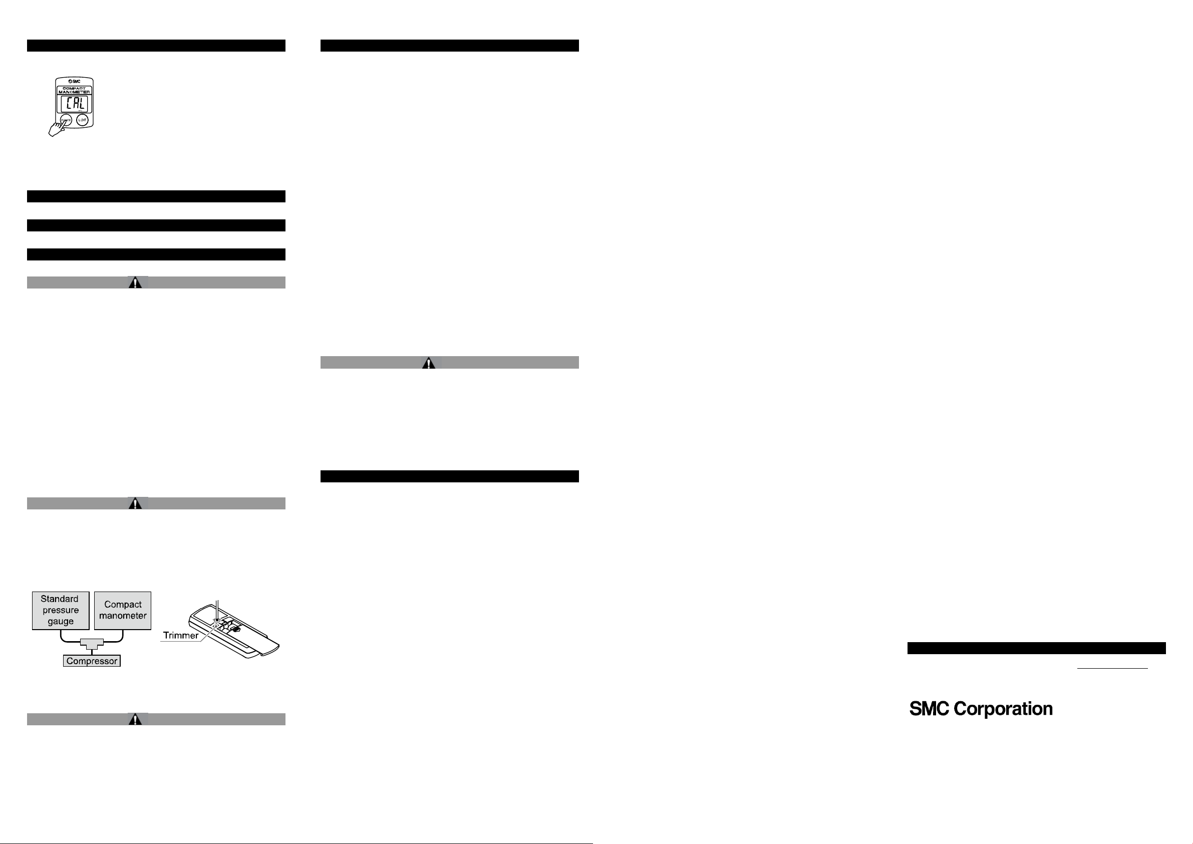
7.2 Span calibration method
Caution
Do not touch the span calibration trimmer except when performing
span calibration.
1. Perform zero clear at atmospheric pressure.
2. Apply the maximum rated pressure, and calibrate the span while
comparing with a standard pressure gauge.
3. If the display value of the compact manometer is “0” after returning to
atmospheric pressure, then calibration is complete.
If the display value is not “0”, calibrate again by repeating steps 1 and 2.
7.3 Replacing the batteries
When battery voltage becomes low the entire LCD will flash.
When the LCD flashes replace the batteries. Use 2 x AA dry batteries.
Caution
To replace the batteries, turn the power OFF and replace them
within approximately 30 seconds.
When not completed within 30 seconds, “Err” will be displayed.
In that case, perform zero clear once again.
In the event that the display runs out of control, remove the batteries for
one minute or longer, and then perform zero clear again for inserting
the batteries and turning on the power.
Therefore, SMC products cannot be used for business or certification
ordained by the metrology (measurement) laws of each country.
9 Disposal
This product is classed as Waste Electrical or Electronic Equipment
according to the WEEE Directive 2012/19/EU and should not be
disposed of as municipal waste, in order to reduce the impact on human
health and the environment.
Remove and dispose of old batteries and the remaining electrical or
electronic equipment according to local environmental regulations.
10 Contacts
Refer to Declaration of Conformity and www.smcworld.com for
contacts.
'SMC Corporation, Akihabara UDX15F, 4-14-1, Sotokanda, Chiyoda-ku, Tokyo
101 0021
Specifications are subject to change without prior notice from the manufacturer.
© 2018 SMC Corporation All Rights Reserved.
Template DKP50047-F-085H
Page 2 of 2
 Loading...