

SMC Networks PFMV5 Series Operation Manual
No. PF※※-OMK0004-F
PRODUCT NAME
Flow sensor
MODEL / Series / Product Number
PFMV5##

-1-
No. PF※※-OMK0004-F
Table of Contents
Safety Instructions 2
Model Indication and How to Order 10
Summary of Product parts 12
Definition and terminology 13
Mounting and Installation 14
Installation 14
Piping 16
Wiring 17
Troubleshooting 18
Specifications 19
Specifications 19
Characteristics data 20
Dimensions 22
-2-
No. PF※※-OMK0004-F
Safety Instructions
These safety instructions are intended to prevent hazardous situations and/or equipment damage.
These instructions indicate the level of potential hazard with the labels of "Caution", "Warning" or "Danger".
They are all important notes for safety and must be followed in addition to International Standards
(ISO/IEC)*1), and other safety regulations.
*1) ISO 4414: Pneumatic fluid power -- General rules relating to systems.
ISO 4413: Hydraulic fluid power -- General rules relating to systems.
IEC 60204-1: Safety of machinery -- Electrical equipment of machines .(Part 1: General requirements)
ISO 10218: Manipulating industrial robots -Safety.
etc.
Caution
Caution indicates a hazard with a low level of risk which, if not avoided, could
result in minor or moderate injury.
Warning
Warning indicates a hazard with a medium level of risk which, if not avoided,
could result in death or serious injury.
Danger
Danger indicates a hazard with a high level of risk which, if not avoided, will
result in death or serious injury.
Warning
1. The compatibility of the product is the responsibility of the person who designs the
equipment or decides its specifications.
Since the product specified here is used under various operating conditions, its compatibility with specific
equipment must be decided by the person who designs the equipment or decides its specifications
based on necessary analysis and test results.
The expected performance and safety assurance of the equipment will be the responsibility of the
person who has determined its compatibility with the product.
This person should also continuously review all specifications of the product referring to its latest catalog
information, with a view to giving due consideration to any possibility of equipment failure when
configuring the equipment.
2. Only personnel with appropriate training should operate machinery and equipment.
The product specified here may become unsafe if handled incorrectly.
The assembly, operation and maintenance of machines or equipment including our products must be
performed by an operator who is appropriately trained and experienced.
3. Do not service or attempt to remove product and machinery/equipment until safety is
confirmed.
1. The inspection and maintenance of machinery/equipment should only be performed after measures to
prevent falling or runaway of the driven objects have been confirmed.
2. When the product is to be removed, confirm that the safety measures as mentioned above are
implemented and the power from any appropriate source is cut, and read and understand the specific
product precautions of all relevant products carefully.
3. Before machinery/equipment is restarted, take measures to prevent unexpected operation and malfunction.
4. Contact SMC beforehand and take special consideration of safety measures if the
product is to be used in any of the following conditions.
1. Conditions and environments outside of the given specifications, or use outdoors or in a place
exposed to direct sunlight.
2. Installation on equipment in conjunction with atomic energy, railways, air navigation, space, shipping,
vehicles, military, medical treatment, combustion and recreation, or equipment in contact with food and
beverages, emergency stop circuits, clutch and brake circuits in press applications, safety equipment or
other applications unsuitable for the standard specifications described in the product catalog.
3. An application which could have negative effects on people, property, or animals requiring special
safety analysis.
4. Use in an interlock circuit, which requires the provision of double interlock for possible failure by using
a mechanical protective function, and periodical checks to confirm proper operation.
-3-
No. PF※※-OMK0004-F
Safety Instructions
Caution
1.The product is provided for use in manufacturing industries.
The product herein described is basically provided for peaceful use in manufacturing industries.
If considering using the product in other industries, consult SMC beforehand and exchange
specifications or a contract if necessary.
If anything is unclear, contact your nearest sales branch.
Limited warranty and Disclaimer/Compliance Requirements
The product used is subject to the following "Limited warranty and Disclaimer" and "Compliance
Requirements".
Read and accept them before using the product.
Limited warranty and Disclaimer
1. The warranty period of the product is 1 year in service or 1.5 years after the product is
delivered, whichever is first.2)
Also, the product may have specified durability, running distance or replacement parts.
Please consult your nearest sales branch.
2. For any failure or damage reported within the warranty period which is clearly our
responsibility, a replacement product or necessary parts will be provided.
This limited warranty applies only to our product independently, and not to any other
damage incurred due to the failure of the product.
3. Prior to using SMC products, please read and understand the warranty terms and
disclaimers noted in the specified catalog for the particular products.
2) Vacuum pads are excluded from this 1 year warranty.
A vacuum pad is a consumable part, so it is warranted for a year after it is delivered.
Also, even within the warranty period, the wear of a product due to the use of the
vacuum pad or failure due to the deterioration of rubber material are not covered by the
limited warranty.
Compliance Requirements
1. The use of SMC products with production equipment for the manufacture of weapons of
mass destruction (WMD) or any other weapon is strictly prohibited.
2. The exports of SMC products or technology from one country to another are governed by
the relevant security laws and regulation of the countries involved in the transaction. Prior
to the shipment of a SMC product to another country, assure that all local rules governing
that export are known and followed.
Caution
SMC products are not intended for use as instruments for legal metrology.
Products that SMC manufactures or sells are not measurement instruments that are qualified by pattern
approval tests relating to the measurement laws of each country.
Therefore, SMC products cannot be used for business or certification ordained by the measurement laws of
each country.
-4-
No. PF※※-OMK0004-F
Operator
This operation manual is intended for those who have knowledge of machinery using pneumatic
equipment, and have sufficient knowledge of assembly, operation and maintenance of such
equipment. Only those persons are allowed to perform assembly, operation and maintenance.
Read and understand this operation manual carefully before assembling, operating or providing
maintenance to the product.
■Safety Instructions
Warning
■Do not disassemble, modify (including changing the printed circuit board) or repair.
An injury or failure can result.
■Do not operate the product outside of the specifications.
Do not use for flammable or harmful fluids.
Fire, malfunction, or damage to the product can result.
Verify the specifications before use.
■Do not operate in an atmosphere containing flammable or explosive gases.
Fire or an explosion can result.
This product is not designed to be explosion proof.
■Do not use the product for flammable fluid.
A fire or explosion can result.
Only air and N2 are applicable.
■Do not use the product in a place where static electricity is a problem.
Otherwise it can cause failure or malfunction of the system.
■If using the product in an interlocking circuit:
Provide a double interlocking system, for example a mechanical system.
Check the product regularly for proper operation
Otherwise malfunction can result, causing an accident.
■The following instructions must be followed during maintenance :
Turn off the power supply
Stop the air supply, exhaust the residual pressure and verify that the air is released before performing
maintenance
Otherwise an injury can result.
-5-
No. PF※※-OMK0004-F
Caution
■Do not touch the terminals and connectors while the power is on.
Otherwise electric shock, malfunction or damage to the product can result.
■After maintenance is complete, perform appropriate functional inspections and leak tests.
Stop operation if the equipment does not function properly or there is a leakage of fluid.
When leakage occurs from parts other than the piping, the product might be faulty.
Disconnect the power supply and stop the fluid supply.
Do not apply fluid under leaking conditions.
Safety cannot be assured in the case of unexpected malfunction.
■NOTE
○Follow the instructions given below when designing, selecting and handling the product.
●The instructions on design and selection (installation, wiring, environment, adjustment, operation,
maintenance, etc.) described below must also be followed.
Product specifications
The direct current power supply used should be UL approved as follows.
Circuit (Class 2) of maximum 30 Vrms (42.4 V peak) or less, with UL1310 Class 2 power supply unit or UL1585
Class 2 transformer.
The product is a UL approved product only if it has a mark on the body.
Use the specified voltage.
Otherwise failure or malfunction can result.
Insufficient supply voltage may not drive a load due to a voltage drop inside the product.
Verify the operating voltage of the load before use.
Do not exceed the specified maximum allowable load.
Otherwise it can cause damage or shorten the lifetime of the product.
Applicable operating fluid depends on the product.
Check the details of the specifications before using.
Before designing piping confirm the pressure loss at the sensor from the pressure loss graph.
Confirm pressure loss of the sensor from the characteristics data.
For the details of compressed air quality, refer to ISO 8573-1, 1.1.2 to 1.6.2.
Use the specified measurement flow rate and operating pressure.
Otherwise it can cause damage to the product or inability to measure correctly.
Reserve a space for maintenance.
Allow sufficient space for maintenance when designing the system.
-6-
No. PF※※-OMK0004-F
●Product handling
Installation
Tighten to the specified tightening torque.
If the tightening torque is exceeded the mounting screws and brackets may damaged.
If the tightening torque is insufficient, the product may be displaced and the mounting screws may come loose
(Refer to page 14 ”Mounting and Installation”.)
Ensure that the FG terminal is connected to ground when using a commercially available switch-mode
power supply.
Do not drop, hit or apply excessive shock to the product.
Otherwise damage to the internal parts can result, causing malfunction.
Do not pull the lead wire forcefully, or lift the product by the lead wire. (Tensile force 49 N or less)
Hold the product body when handling, to prevent damage, failure or malfunction
When connecting the piping, hold the specified part of the body with a spanner.
Hold the product body when handling, to prevent damage, failure or malfunction
Any dust left in the piping should be flushed out by air blow before connecting the piping to the product.
Otherwise it can cause damage or malfunction.
Refer to the flow direction of the fluid indicated on the product label for installation and piping.
Do not mount the body with the bottom facing upwards.
Retention of air can cause inability to measure accurately.
Do not insert metal wires or other foreign matter into the piping port.
This can damage the sensor causing failure or malfunction.
Never mount a product in a location that will be used as a foothold.
The product may be damaged if excessive force is applied by stepping or climbing onto it.
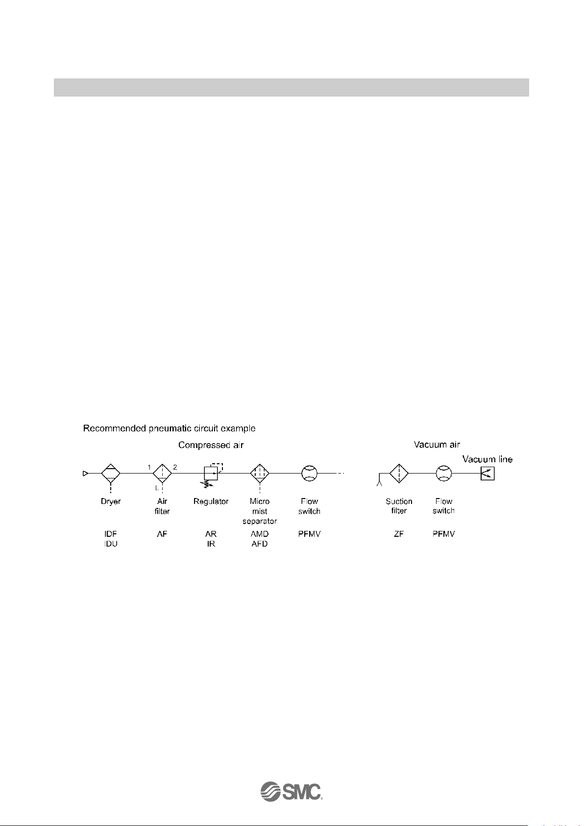
If there is a risk of foreign matter entering the fluid, install and pipe a filter or the mist separator at the
inlet to avoid failure and malfunction.
Refer to the figure below for the recommended pneumatic circuit.

-7-
No. PF※※-OMK0004-F
Wiring
Do not pull the lead wires.
In particular, never lift a product equipped with fitting and piping by holding the lead wires.
Otherwise damage to the internal parts can result, causing malfunction.
Avoid repeatedly bending or stretching the lead wire, or placing heavy loads on it
Repeated bending stress or tensile stress can cause damage to the sheath, or breakage of the wires.
If the lead wire can move, fix it near the body of the product.
The recommended bend radius of the lead wire is 6 times the outside diameter of the sheath, or 33 times the
outside diameter of the wire insulation material, whichever is larger.
Replace any damaged lead wire with a new one.
Wire correctly.
Incorrect wiring can damage the product.
Do not perform wiring while the power is on.
Otherwise damage to the internal parts can result, causing malfunction.
Do not route wires and cables together with power or high voltage cables.
Otherwise the product can malfunction due to interference or noise and surge voltage from power and high voltage
cables.
Confirm proper insulation of wiring.
Poor insulation (interference from another circuit, poor insulation between terminals, etc.) can lead to excess
voltage or current being applied to the product, causing damage.
Keep wiring as short as possible to prevent interference from electromagnetic noise and surge voltage.
Do not use a cable longer than 30 m.
Wire the DC (-) line (blue) as close as possible to the power supply.
When analogue output is used, install a noise filter (line noise filter, ferrite element, etc.) between the
switch-mode power supply and this product.
 Loading...