

SMC Networks PFMV3 Series Operation Manual
Flow Monitor
Operation Manual
PFMV3
Safety Instructions
Safety Instructions
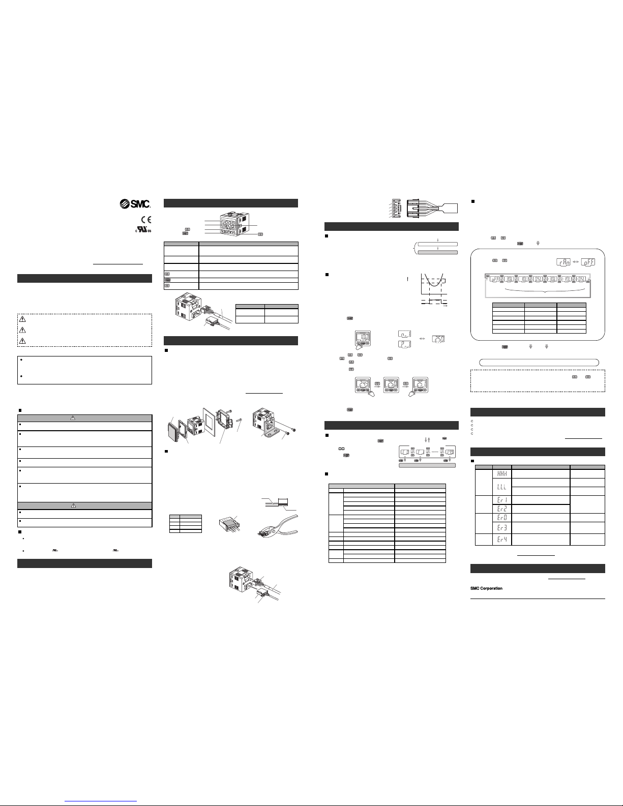
Summary of Product parts
Mounting and Installation
button (UP)
button (SET)
button (DOWN)
Indicator LED (OUT2)
I
ndicator LED (OUT1)
LCD Display
CAUTION indicates a hazard with a low level of risk which, if
n
ot avoided, could result in minor or moderate injury.
Caution:
Warning:
Danger:
WARNING indicates a hazard with a medium level of risk
w
hich, if not avoided, could result in death or serious injury.
D
ANGER indicates a hazard with a high level of risk which, if
not avoided, will result in death or serious injury.
L
CD Display
Displays the flow value, setting mode, and error indication.
F
our display modes can be selected: display always in red or green, or display
changing from green to red, or red to green, according to the output status (OUT1).
Indicator LED (OUT1)
Indicates the output status of OUT1.
LED is ON (Green) when OUT1 is ON.
Indicator LED (OUT2)
Indicates the output status of OUT2.
LED is ON (Red) when OUT2 is ON.
button (UP)
Selects the mode or increases the ON/OFF set value.
P
ress this button to change to the peak display mode.
button (SET)
Press this button to change to another mode and to set a value.
Item Description
Thank you for purchasing an SMC PFMV3 Series Flow Monitor.
Please read this manual carefully before operating the product and make sure you
understand its capabilities and limitations.
Please keep this manual handy for future reference.
To obtain more detailed information about operating this product,
p
lease refer to the SMC website (URL http://www.smcworld.com
)
or
contact SMC directly.
These safety instructions are intended to prevent hazardous situations and/or
equipment damage.
These instructions indicate the level of potential hazard with the labels of
"Caution", "Warning" or "Danger". They are all important notes for safety and must
b
e followed in addition to International standards (ISO/IEC) and other safety
regulations.
Operator
This operation manual is intended for those who have knowledge of machinery
u
sing pneumatic equipment, and have sufficient knowledge of assembly,
operation and maintenace of such equipment. Only those persons are allowed
to perform assembly, operation and maintenance.
R
ead and understand this operation manual carefully before assembling,
operating or providing maintenance to the product.
D
o not operate the product outside of the specifications.
Do not use for flammable or harmful fluids.
Fire, malfunction, or damage to the product can result.
Verify the specifications before use.
D
o not disassemble, modify (including changing the printed circuit board) or repair.
A
n injury or failure can result.
Do not operate in an atmosphere containing flammable or explosive gases.
Fire or an explosion can result.
This product is not designed to be explosion proof.
Do not use the product in a place where static electricity is a problem.
Otherwise it can cause failure or malfunction of the system.
If using the product in an interlocking circuit:
•Provide a double interlocking system, for example a mechanical system.
•Check the product regularly for proper operation.
Otherwise malfunction can result, causing an accident.
The following instructions must be followed during maintenance :
•Turn off the power supply
•Stop the air supply, exhaust the residual pressure and verify that the air is released before performing
maintenance work
Otherwise an injury can result.
After maintenance is complete, perform appropriate functional inspections and leak tests.
Stop operation if the equipment does not function properly or there is a leakage of fluid.
Do not touch the terminals and connectors while the power is on.
Otherwise electric shock, malfunction or damage to the product can result.
Warning
Caution
NOTE
The direct current power supply used should be UL approved as follows.
Circuit (of class 2) which is of maximum 30Vrms (42.4 V peak), with UL 1310
class 2 power supply unit or UL 1585 class 2 transformer.
The product is a approved product only if it has a mark on the body.
button (DOWN)
Selects the mode or decreases the ON/OFF set value.
P
ress this button to change to the bottom display mode.
Mounting screw (M3 x 5 L)
Bracket
Installation
P
anel mounting
•
Fix the panel mount adapter to the product with the mounting screws (nominal size:
3 x 8 L, 2 pcs.) supplied.
•The monitor can be mounted on a panel with a thickness of 0.5 to 6.0 mm.
Bracket mounting
•Mount the bracket using the mounting screws (M3 x 5 L) supplied.
•The required tightening torque is 0.5 to 0.7 Nm.
•
Install the product (with bracket) using the M4 screws (2 pcs.).
•Bracket thickness is approximately 1.6 mm.
R
efer to the product catalogue or SMC website (URL http://www.smcworld.com
)
for more
information about panel cut-out and mounting hole dimensions.
<
Operation>
∗: The Product outputs will continue operating during setting.
1
. Press the button in measurement mode to display the set values.
[
P_1] or [n_1] and the set value are displayed in turn.
∗
: [LLL] is displayed during measurement mode when the sensor is not connected.
3
. Press the button to complete the setting of OUT1.
[n_2] or [P_2] will be displayed. Set as above.
PFMV
V
Displayed in turn
Normal output
Reversed output
PFMV
V
PFMV
V
PFMV
V
Flow Setting
Measurement mode
T
he mode in which the flow is detected
and displayed, and the switch function is
o
perating. This is the basic operating
mode; other modes should be selected for
s
et-point and other Function Setting changes.
∗: The display will indicate [LLL] if a sensor is not connected.
Power is supplied
The product identification is displayed
Measurement mode
(the output remains off
for this period)
approx.3 seconds
Switch operation
W
hen the flow (or voltage) falls below the set
v
alue by the amount of hysteresis or more, the
s
witch will turn ON.
W
hen the flow (or voltage) exceeds the set value,
t
he switch will turn OFF.
I
f this condition, shown to the right, is acceptable,
t
hen keep these settings.
S
w
i
t
ch
O
N
S
w
i
t
ch
O
F
F
S
e
t
v
a
l
u
e
n
_
1
T
i
m
e
[
s]
V
o
l
t
a
g
e
[
V
]
F
l
o
w
[
L
/
m
i
n
]
H
y
s
t
e
r
e
s
i
s
H
_
1
Other Settings
Standard value offset function
Peak/Bottom value display
Indicated content check function
Key lock function
To set each of these functions, refer to the SMC website (URL http://www.smcworld.com
)
for more detailed information, or contact SMC.
Troubleshooting
Error indication
Input voltage
flow error
The flow (input voltage) has exceeded the upper
limit of the display range.
Reduce input voltage
(= flow).
Error name Error display Error type Troubleshooting method
Overcurrent
error
The switch output load current (OUT1) has
exceeded 80 mA.
The switch output load current (OUT2) has
exceeded 80 mA.
Turn off the power supply
and remove the cause of
the over current. Then
supply the power again.
System error
The product has lost the factory adjustment
settings. The internal circuit may be damaged.
Stop operation immediately
and contact SMC.
Standard
value offset
error
Perform the standard value
offset under no flow
conditions.
The standard value offset function has been
performed outside the effective range for
correction.
System error.
The product has failed to store the data, or the
internal circuit may be damaged.
Turn the power off and turn
it on again, then repeat the
Function Setting.
The flow (input voltage) is less than the lower
limit of the display range.
Increase input voltage
(= flow).
Note: Specifications are subject to change without prior notice and any obligation on the part of the manufacturer.
© 2011 SMC Corporation All Rights Reserved
Akihabara UDX 15F, 4-14-1, Sotokanda, Chiyoda-ku, Tokyo 101-0021, JAPAN
Phone: +81 3-5207-8249 Fax: +81 3-5298-5362
URL http://www.smcworld.com
Function selection mode
In measurement mode, press the button
for 2 seconds or longer, to display [F 0].
The [F ] indicates the mode for changing
each function setting.
Press the button for 2 seconds or longer
in function selection mode to return to
measurement mode.
Function Setting
Measurement mode
Function selection mode
Function Setting
Press the button
for 2 seconds or longer
Mounting screw
Panel mount adapter (can be rotated 90 degrees for mounting).
Front protective
cover (option)
A sensor may be disconnected or wired
incorrectly.
Check the connection and
wiring of the sensor.
Sensor connector
P
ower and output
lead wire and
connector
Front
B
ack
P
ower and output lead
w
ire and connector
C
able to supply power and
t
ransmit output signals.
Sensor connector
C
onnector for sensor
l
ead wire.
Item Description
Attaching the connector to the sensor wire
•Strip the sensor wire as shown.
•Do not cut the insulator.
•Insert the corresponding wire colour shown in the table into the
pin number printed on the sensor connector, to the bottom.
Wiring
Wiring of connector
•Connections should only be made with the power supply turned off.
•Use separate routes for the product wiring and any power or high voltage wiring.
Otherwise, malfunction may result due to noise.
•Ensure that the FG terminal is connected to ground when using a commercially
available switch-mode power supply. When a switch-mode power supply is connected
to the product, switching noise will be superimposed and the product specification can
no longer be met. This can be prevented by inserting a noise filter, such as a line noise
filter and ferrite core, between the switch-mode power supply and the product, or by
using a series power supply instead of a switch-mode power supply.
more than 20 mmCover
Insulator
A
1
2
Pin no.
Brown (DC+)
NC
Wire colour
3
4
Blue (DC−)
Black (IN (1 to 5 V))
•
Check that the above preparation has been performed
correctly, then part A shown should be pressed in by hand to make temporary connection.
•Part A should then be pressed in using a suitable tool, such as pliers.
•The sensor connector cannot be re-used once it has been fully crimped.
In cases of connection failure such as incorrect order of wires or incomplete insertion,
please use a new connector.
•If the sensor is not connected correctly “LLL” or “HHH” will be displayed.
Connecting / Disconnecting
•When mounting the connector, insert it
straight into the socket, holding the
lever and connector body, and push the
connector until the lever hooks into the
housing, and locks.
•When removing the connector, press
down the lever to release the hook from
the housing and pull the connector
straight out.
Power and output
lead wire
and connector
Connector for sensor
lead wire
Lever
Lever
1
DC(-) Blue
DC(+) Brown
OUT1 Black
O
UT2 White
Analogue output / External input Grey
2
3
4
5
P
ower and output connector
p
in numbers
[F95]
Selection of flow indication
T
he flow rate can be displayed. The flow rate units can be selected (for models with unit
selection function) after selecting the connected sensor.
L
/min. or CFM(ft
3
/
min.) x 10
-
2
a
re the selectable display units.
To use for flow rate indication, select the sensor and units before setting the functions
[
F1], [F2], [F4].
The set values for [F1], [F2] and [F4] will be reset when the flow indication setting is
c
hanged.
Default setting
The default settings are provided as follows. If these settings are acceptable, retain for use.
Item
[oU1] Output mode (OUT1)
[1ot ] Reversed output (OUT1)
[H_1] Setting of hysteresis (OUT1)
[CoL] Display colour
Default setting
[
HYS
] Hysteresis mode
[
1_n
] Reversed output
[
0.12
] (Voltage display)
[
SoG
] ON: Green OFF: Red
[oU2] Output mode (OUT2)
[2ot ] Reversed output (OUT2)
[
n_2
] Input of Set value (OUT2)
[H_2] Setting of hysteresis (OUT2)
[
HYS
] Hysteresis mode
[
2_n
] Normal output
[
2.50
] (Voltage display)
[
0.12
] (Voltage display)
[
rES
] Response time
[ inP
] External input
[
.002
] 2 msec.
[oFF] Unused
[
n_1
] Input of set value (OUT1)
[
2.50
] (Voltage display)
[
Eco
] Power saving mode
[P in] Security code
[oFF] Unused
[oFF] Unused
Auto-preset
-
[F 0]
[F 1]
[F 2]
[F 3]
[F 4]
[F 5]
[F 6]
[F95]
[F99]
[
r An
] Select connected sensor [oFF] Unused
[Un i] Unit selection function
[ in i ] Reset to the default settings
[
LPm
] L/min
[oFF] Unused
∗: If the error cannot be reset after the above measures are taken, then please contact SMC.
Specifications / Outline with Dimensions
Refer to the product catalogue or SMC website (URL http://www.smcworld.com) for more
information about the product specifications and outline dimensions.
Refer to the SMC website (URL http://www.smcworld.com
) for more information about
troubleshooting.
T
o use the product for flow rate indication, select the connected flow sensor using
function [F95] before setting any other functions.
S
tandard value offset function
The dis play can be off set to the stan dard value by pr essing the and but tons
s
imultaneously for 1 second or longer.
For the initial op eration, always perform the standard value offset function with no f low
a
pplied.
<
Operation>
Press the or button in function selection mode to display [F95].
P
ress the button.
S
elect connected sensor
[
rAn] and the set value are displayed in turn.
P
ress the or button to select.
Flow display
PFMV530 PFMV510 PFMV505 PFMV530F PFMV510F PFMV505F
V
oltage
display
Displayed in turn
Flow range Set value
PFMV505
C
onnected sensor model
PFMV510
PFMV505F
P
FMV530
PFMV510F
PFMV530F
3
.0 L
D
isplayed flow range
1.0 L
-3.0 L
0.5 L
-1.0 L
-0.5 L
0
to 3.0 [L/min]
R
ated flow range
0 to 1.0 [L/min]
-3.0 to 3.0 [L/min]
0
to 0.5 [L/min]
-0.5 to 0.5 [L/min]
∗: The set values of OUT1 and OUT2 will be reset when the flow range setting is changed.
S
election of flow indication completed. Return to Function selection mode.
Maintenance
How to reset the product after a power cut forcible de-energizing
The setting of the product will be retained as it was before a power cut or de-energizing.
The output condition is also basically recovered to that before a power cut or de-energizing,
but may change depending on the operating environment.
Therefore, check the safety of the whole installation before operating the product.
2. Press the or button to change the set value.
T
he button is to increase and the button is to decrease the set value.
•
Press the button once to increase by one digit, or press it continuously to keep
increasing the set value.
•
Press the button once to decrease by one digit, or press it continuously to keep
decreasing the set value.
-1.0 to 1.0 [L/min]
Press the button to set. Move on to unit selection function
(
for models with unit selection
function).
 Loading...