

SMC Networks PFM5 Series Installation & Maintenance Manual

P
FM5##-TFN13
Installation & Maintenance Manual
Flow Sensor
Series PFM5
S
afety Instructions
•Do not touch the terminals and connectors while the power is on.
Otherwise electric shock, malfunction or damage to the product can result.
•After maintenance is complete, perform appropriate functional
inspections and leak tests.
Stop operation if the equipment does not function properly or there is a
leakage of fluid.
When leakage occurs from parts other than the piping, the product is
faulty.
Disconnect the power supply and stop the fluid supply.
Do not apply fluid under leaking conditions.
Safety cannot be assured in the case of unexpected malfunction.
NOTE
•The direct current power supply to be used should be UL approved as
follows:
Circuit (class 2) which is of maximum 30 Vrms (42.4 V peak), with UL 1310
class 2 power supply unit or UL 1585 class 2 transformer.
•The Flow sensor is a approved product only if it has a mark
on the body.
•Do not disassemble, modify (including changing the printed circuit
board) or repair.
An injury or failure can result.
•Do not operate the product outside of the specifications.
Do not use for flammable or harmful fluids.
Fire, malfunction, or damage to the product can result.
Verify the specifications before use.
•Do not operate in an atmosphere containing flammable or
explosive gases.
Fire or an explosion can result.
This product is not designed to be explosion proof.
•Do not use the product in a place where static electricity is a
problem.
Otherwise it can cause failure or malfunction of the system.
•If using the product in an interlocking circuit:
•Provide a double interlocking system, for example a mechanical
system
•Check the product regularly for proper operation
Otherwise malfunction can result, causing an accident.
•The following instructions must be followed during maintenance:
•Turn off the power supply
•Stop the air supply, exhaust the residual pressure and verify that
the air is released before performing maintenance.
Otherwise an injury can be caused.
Caution
Names and Functions of Individual Parts
Installation
Model Indication and How to Order
Panel mounting
•Insert Panel Mount Adapter B (supplied as an accessory) into Section A of
Panel Mount Adapter A.
Push Panel Mount Adapter B from behind until the display is fixed onto the
panel.
The pin of Panel Mount Adapter B engages the notched part of Panel
Adapter C to fix the display.
•The switch can be mounted on a panel with a thickness of 1 to 3.2 mm.
•See the illustration below for panel cut out dimensions.
Warning
Safety Instructions (Continued)
Refer to the operation manual and the product catalogue for more detailed
information.
I
N
Flow adjustment valve
Knurl
Piping port
Power source display
Flow display
Body
Through hole
Power source display (green): Turns on when power is supplied.
Flow display (green): Flashing interval depends on the flow value.
As flow increases, flash interval is shortened.
The light turns to red when rated flow is exceeded.
Body: Product itself.
Flow adjustment valve: Orifice mechanism to adjust the flow.
Piping port: Connection port for piping.
Knurl: Used to lock the flow adjustment valve.
Through hole: Used to mount the product on a DIN rail or a panel directly.
Bracket mounting
•Fasten the bracket mounting screws to a torque of 0.5±0.05 Nm.
Self tapping
screws
Piping
•Ensure tightening torque is correct when installing piping.
•Refer to the following table for the appropriate torque values.
•Hold the metal part with a spanner when piping.
•For one-touch fitting, insert the tube to the end so that it cannot be
pulld out.
•Insertion with excessive force can cause damage.
•Ensure there is no leakage after piping.
•Use this product within the specified operating pressure range and
operating temperature range.
•Withstand pressure is 1.0 MPa.
Installation (Continued)
Self tapping
screws
Without flow adjustment valve
(using ZS-33-M)
With flow adjustment valve
(using ZS-33-MS)
DIN rail mounting
•The tightening torque for DIN rail mounting screws and joint screws should
be 0.4±0.05 Nm.
DIN rail mounting
screws
Bracket
Joint screw
DIN rail mounting
bracket
Through hole
Note) DIN rail mounting is not suitable for
models with port type F02: G1/4.
Rc1/8
Rc1/4
Nominal size of screws
7 to 9
12 to 14
Appropriate torque Nm
Without flow adjustment valve
With flow adjustment valve
Dimension A
ZS-33-J
ZS-33-JS
Adapter
Wiring
Connection
•Make connection after turning the power off.
•Use a separate route when installing wire. Malfunction stemming from
noise may occur if wire is installed in the same route as that of power or
high-voltage cable.
•Be sure to ground terminal FG when using a switching regulator
obtained on the market. If analogue output is performed connecting to a
switching regulator obtained on the market, switching noise will be
superimposed and product specification can no longer be met. This can
be prevented by inserting a noise filter, such as a line noise filter and a
ferrite element, between the switching regulator and the pressure
switch, or by using a series power supply instead of a switching
regulator.
Connector
Connecting/Disconnecting
•When connecting the connector, insert it straight onto the pin holding
the lever and connector body between fingers and lock the connector by
pushing the lever claw into the square groove in the body of the sensor.
•When disconnecting the connector, push down the lever by thumb to
disengage the lever claw from the square groove. Then pull the
connector straight out.
Body of sensor
Lever
Cover (Option: ZS-33-F)
Lead wire connector
WARNING indicates a hazard with a medium level
of risk which, if not avoided, could result in death or
serious injury.
DANGER indicates a hazard with a high level of risk
which, if not avoided, will result in death or serious
injury.
CAUTION indicates a hazard with a low level of risk
which, if not avoided, could result in minor or
moderate injury.
Caution
Warning
Danger
This product is class A equipment that is intended for use in an industrial
environment.
There may be potential difficulties in ensuring electromagnetic
compatibility in other environments due to conducted as well as radiated
disturbances.
+0.5
0
54
+0.5
0
74
This manual contains essential information for the protection of users
and others from possible injury and/or equipment damage.
•Read this manual before using the product, to ensure correct handling,
and read the manuals of related apparatus before use.
•Keep this manual in a safe place for future reference.
•These instructions indicate the level of potential hazard by label of
"Caution", "Warning" or "Danger", followed by important safety
information which must be carefully followed.
•To ensure safety of personnel and equipment the safety instructions in
this manual and the product catalogue must be observed, along with
other relevant safety practices.
A
Panel Mount
Adapter A
Panel
Panel Mount
Adapter B
Push
Insert
Bracket
Section A
2
4
+
0
.
5
0
Section C
P
FM5##-TFN13
Error Indication Function
Maintenance
How to reset the product after power cut or de-energizing
The setting of the product will be retained as it was before a power cut
or de-energizing.
The output condition is also basically recovered to that before a power
cut or de-energizing, but may change depending on the operating
environment. Therefore, check the safety of the whole facility before
operating the product.
Specification
Refer to the operation manual and the product catalogue for more
detailed information.
Outline with Dimensions (in mm)
Refer to the operation manual and the product catalogue for more
detailed information.
Contact
AUSTRIA (43) 2262 62280 NETHERLANDS (31) 20 531 8888
BELGIUM (32) 3 355 1464 NORWAY (47) 67 12 90 20
CZECH REP. (420) 541 424 611 POLAND (48) 22 211 9600
DENMARK (45) 7025 2900 PORTUGAL (351) 21 471 1880
FINLAND (358) 207 513513 SLOVAKIA (421) 2 444 56725
FRANCE (33) 1 6476 1000 SLOVENIA (386) 73 885 412
GERMANY (49) 6103 4020 SPAIN (34) 945 184 100
GREECE (30) 210 271 7265 SWEDEN (46) 8 603 1200
HUNGARY (36) 23 511 390 SWITZERLAND (41) 52 396 3131
IRELAND (353) 1 403 9000 UNITED KINGDOM (44) 1908 563888
ITALY (39) 02 92711
URL http://www.smcworld.com (Global) http://www.smceu.com (Europe)
Specifications are subject to change without prior notice from the manufacturer.
©2009 SMC Corporation All Rights Reserved.
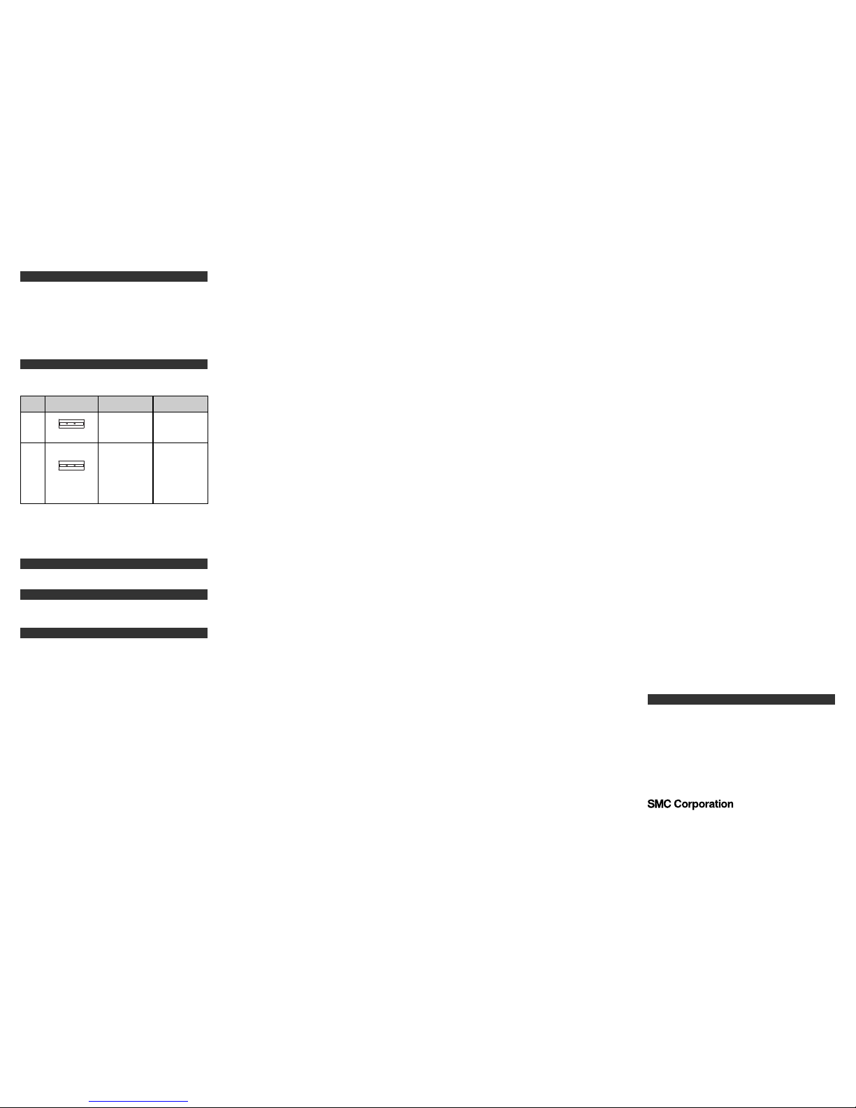
Error
Name
TroubleshootingError Content
Flow
Error
Error
Display
Flow display is red.
POWER FLOW
Flow exceeds rated
flow range.
Apply flow within
rated flow range.
This function is to display error location and content when a problem or
an error has occured.
System
Error
Power source
display is red.
P
OWER FLOW
System error.
Possible damage of
internal circuit.
Turn off the power
supply to clear the
error.
Then supply the
power again.
Troubleshooting
Refer to the operation manual for this product.
If the error can not be reset after the above measures are taken, then
please contact SMC.
 Loading...