

No.PF※※-OMN0010-J
PRODUCT NAME
Digital Flow Switch
(Remote type sensor unit)
MODEL / Series / Product Number
PF3W5##

-1-
No.PF※※-OMN0010-J
Table of Contents
Safety Instructions 2
Model Indication and How to Order 11
Summary of Product parts 14
Definition and terminology 15
Mounting and Installation 16
Installation 17
Piping 19
Wiring 22
Flow Measurement 23
Maintenance 24
Troubleshooting 25
Specification 28
Specifications 28
Characteristics graph 32
Analogue output 40
Dimensions 41
Made to Order 48
-2-
No.PF※※-OMN0010-J
Safety Instructions
These safety instructions are intended to prevent hazardous situations and/or equipment damage.
These instructions indicate the level of potential hazard with the labels of "Caution", "Warning" or "Danger".
They are all important notes for safety and must be followed in addition to International Standards (ISO/IEC)*1),
and other safety regulations.
*1) ISO 4414: Pneumatic fluid power -- General rules relating to systems.
ISO 4413: Hydraulic fluid power -- General rules relating to systems.
IEC 60204-1: Safety of machinery -- Electrical equipment of machines .(Part 1: General requirements)
ISO 10218: Manipulating industrial robots -Safety.
etc.
Caution
Caution indicates a hazard with a low level of risk which, if not avoided, could
result in minor or moderate injury.
Warning
Warning indicates a hazard with a medium level of risk which, if not avoided,
could result in death or serious injury.
Danger
Danger indicates a hazard with a high level of risk which, if not avoided, will
result in death or serious injury.
Warning
1. The compatibility of the product is the responsibility of the person who designs the
equipment or decides its specifications.
Since the product specified here is used under various operating conditions, its compatibility with specific
equipment must be decided by the person who designs the equipment or decides its specifications
based on necessary analysis and test results.
The expected performance and safety assurance of the equipment will be the responsibility of the person
who has determined its compatibility with the product.
This person should also continuously review all specifications of the product referring to its latest catalog
information, with a view to giving due consideration to any possibility of equipment failure when
configuring the equipment.
2. Only personnel with appropriate training should operate machinery and equipment.
The product specified here may become unsafe if handled incorrectly.
The assembly, operation and maintenance of machines or equipment including our products must be
performed by an operator who is appropriately trained and experienced.
3. Do not service or attempt to remove product and machinery/equipment until safety is
confirmed.
1. The inspection and maintenance of machinery/equipment should only be performed after measures to
prevent falling or runaway of the driven objects have been confirmed.
2. When the product is to be removed, confirm that the safety measures as mentioned above are
implemented and the power from any appropriate source is cut, and read and understand the specific
product precautions of all relevant products carefully.
3. Before machinery/equipment is restarted, take measures to prevent unexpected operation and malfunction.
4. Contact SMC beforehand and take special consideration of safety measures if the
product is to be used in any of the following conditions.
1. Conditions and environments outside of the given specifications, or use outdoors or in a place
exposed to direct sunlight.
2. Installation on equipment in conjunction with atomic energy, railways, air navigation, space, shipping,
vehicles, military, medical treatment, combustion and recreation, or equipment in contact with food and
beverages, emergency stop circuits, clutch and brake circuits in press applications, safety equipment or
other applications unsuitable for the standard specifications described in the product catalog.
3. An application which could have negative effects on people, property, or animals requiring special
safety analysis.
4. Use in an interlock circuit, which requires the provision of double interlock for possible failure by using
a mechanical protective function, and periodical checks to confirm proper operation.
-3-
No.PF※※-OMN0010-J
Safety Instructions
Caution
1.The product is provided for use in manufacturing industries.
The product herein described is basically provided for peaceful use in manufacturing industries.
If considering using the product in other industries, consult SMC beforehand and exchange specifications
or a contract if necessary.
If anything is unclear, contact your nearest sales branch.
Limited warranty and Disclaimer/Compliance Requirements
The product used is subject to the following "Limited warranty and Disclaimer" and "Compliance
Requirements".
Read and accept them before using the product.
Limited warranty and Disclaimer
1. The warranty period of the product is 1 year in service or 1.5 years after the product is delivered,
whichever is first.2)
Also, the product may have specified durability, running distance or replacement parts. Please
consult your nearest sales branch.
2. For any failure or damage reported within the warranty period which is clearly our responsibility,
a replacement product or necessary parts will be provided.
This limited warranty applies only to our product independently, and not to any other damage
incurred due to the failure of the product.
3. Prior to using SMC products, please read and understand the warranty terms and disclaimers
noted in the specified catalog for the particular products.
2) Vacuum pads are excluded from this 1 year warranty.
A vacuum pad is a consumable part, so it is warranted for a year after it is delivered.
Also, even within the warranty period, the wear of a product due to the use of the vacuum
pad or failure due to the deterioration of rubber material are not covered by the limited
warranty.
Compliance Requirements
1. The use of SMC products with production equipment for the manufacture of weapons of mass
destruction (WMD) or any other weapon is strictly prohibited.
2. The exports of SMC products or technology from one country to another are governed by the
relevant security laws and regulation of the countries involved in the transaction. Prior to the
shipment of a SMC product to another country, assure that all local rules governing that export
are known and followed.
Caution
SMC products are not intended for use as instruments for legal metrology.
Products that SMC manufactures or sells are not measurement instruments that are qualified by pattern
approval tests relating to the measurement laws of each country.
Therefore, SMC products cannot be used for business or certification ordained by the measurement laws of
each country.
-4-
No.PF※※-OMN0010-J
Operator
This operation manual is intended for those who have knowledge of machinery using pneumatic
equipment, and have sufficient knowledge of assembly, operation and maintenance of such
equipment. Only those persons are allowed to perform assembly, operation and maintenance.
Read and understand this operation manual carefully before assembling, operating or providing
maintenance to the product.
■Precautions
Warning
■Do not disassemble, modify (including changing the printed circuit board) or repair.
An injury or failure can result.
■Do not operate the product outside of the specifications.
Do not use for flammable or harmful fluids.
Fire, malfunction, or damage to the product can result.
Verify the specifications before use.
■Do not operate in an atmosphere containing flammable or explosive gases.
Fire or an explosion can result.
This product is not designed to be explosion proof.
■Do not use with flammable or highly permeable fluids.
Fire, explosion, damage or corrosion can result.
■Do not use the product in a place where static electricity is a problem.
Otherwise it can cause failure or malfunction of the system.
■If using the product in an interlocking circuit:
Provide a double interlocking system, for example a mechanical system.
Check the product regularly for proper operation.
Otherwise malfunction can result, causing an accident.
■The following instructions must be followed during maintenance:
Turn off the power supply.
Ensure the flow is shut off before performing maintenance.
Otherwise an injury can result.
-5-
No.PF※※-OMN0010-J
Caution
■Do not touch the terminals and connectors while the power is on.
Otherwise electric shock, malfunction or damage to the product can result.
■Do not touch the piping or its connected parts when the fluid is at high temperature.
It may lead to burnt.
Ensure the piping cools sufficiently before touching.
■After maintenance is complete, perform appropriate functional inspections and leak tests.
Stop operation if the equipment does not function properly or there is a leakage of fluid.
When leakage occurs from parts other than the piping, the product might be faulty.
Disconnect the power supply and stop fluid supply.
Do not apply fluid under leaking conditions.
Safety cannot be assured in the case of unexpected malfunction.
■NOTE
○Follow the instructions given below when designing, selecting and handling the product.
●The instructions on design and selection (installation, wiring, environment, adjustment, operation,
maintenance, etc.) described below must also be followed.
Product specifications
The direct current power supply to be used should be UL approved as follows.
Circuit (of class 2) which is of maximum 30 Vrms (42.4 V peak) or less, with UL 1310 class 2 power supply unit or
UL 1585 class 2 transformer.
The product is a UL approved product only if it has a mark on the body.
Use the specified voltage.
Otherwise failure or malfunction can result.
Insufficient supply voltage may not drive a load due to a voltage drop inside the product.
Verify the operating voltage of the load before use.
Do not exceed the specified maximum allowable load.
Otherwise it can cause damage or shorten the life of the product.
Confirm the pressure loss at the sensor according to the flow rate characteristics (pressure loss) graph
before designing piping.
Confirm detection condition of sensor electrified potential.
The applicable fluids are water (0 to 90 oC) and ethylene glycol solution with a viscosity of 3 mPas
(3 cP) or less.
Fluids other than those mentioned above will not be guaranteed.
Do not use fluids containing chemicals, synthetic oils, organic solvents, salt or corrosive gases.
Using such fluids can result in malfunction and damage to the product.
Check the details of the specifications before use.
Do not touch the piping or its connected parts when the fluid is at high temperature.
It may lead to burnt.
The rated pressure range and proof pressure vary depending on the fluid temperature.
Verify the specifications before use.
Consider measures to prevent over pressure due to water hammer.
<Measures to reduce water hammer>
1. Install a water hammer relieving valve.
2. Use a flexible material for piping (such as a rubber hose) and an accumulator that can absorb impact pressure.
3. Keep piping as short as possible.
Use the product within the specified operating pressure and temperature range.
Reserve a space for maintenance.
Allow sufficient space for maintenance when designing the system.

-6-
No.PF※※-OMN0010-J
●Product handling
Installation
Tighten to the specified tightening torque.
If the tightening torque is exceeded the mounting screws, brackets and the product can be broken. Insufficient
torque can cause displacement of the product from its proper position and the looseness of the mounting screws.
(Refer to "Mounting and Installation" on page 16.)
Be sure to ground terminal FG when using a commercially available switch-mode power supply.
Do not use in a place subject to heavy vibration and/or shock.
Otherwise damage to the internal parts can result, causing malfunction.
Do not pull the lead wire forcefully, not lift the product by pulling the lead wire. (Tensile force 49 N or
less)
Hold the body when handling to avoid the damage of the product.
The product will be damaged, leading to failure and malfunction.
For piping of the product, hold the piping with a spanner on the metal part of the piping (Piping
attachment).
Applying the spanner to other parts may lead to damage to the product.
In particular, do not let the spanner come into contact with the M8 connector.
The connector can be easily damaged.
Eliminate any dust left in the piping by air blow before connecting the piping to the product.
Otherwise it can cause damage or malfunction.
Refer to the flow direction of the fluid indicated on the model number plate or the body for installation
and piping.
Residual air can cause errors in measurement accuracy.
Avoid piping in which the piping size of the IN side of the switch changes suddenly.
If the piping size is reduced sharply or there is a restrictor such as a valve on the IN side, fluid velocity distribution in
the piping will be disturbed, leading to improper measurement.
Therefore, the above-mentioned piping should be connected on the OUT side.
If the OUT side is opened, or flow rate is excessive, cavitations may be generated, which may result in improper
measurement.
As a measure against this, it is possible to reduce the cavitations by increasing the fluid pressure.
Take action such as mounting an orifice on the OUT side of the switch, and confirm that there is no malfunction
before handling.
If the orifice of the OUT side is fully closed to operate the pump, the switch may malfunction due to the effect of
pulsation (pressure fluctuation). Ensure that there is no malfunction before usage.
Do not insert metal wires or other foreign objects into the flow path.
Such actions can damage the sensor causing failure or malfunction.
Never mount the product in a location that will be used as a scaffold.
The product may be damaged if excessive force is applied by stepping or climbing onto it.
If the fluid may contain foreign matter, install and connect a filter or mist separator to the inlet.
The adherence of foreign matter to the vortex generator or detector can cause errors in measurement accuracy.
A filter of approx. 40 mesh is recommended.
Design and install the application so that the fluid detection path is always full.
If the product is mounted vertically, let the liquid flow from bottom to top.
Trapped air bubbles can cause errors in measurement accuracy.
(If the fluid detection path is always filled with liquid, there will be no problem.)
Please be aware that water droplets may cause early deterioration/damage, particularly if the product is installed
vertically or upside-down.
The product body is made of resin. Do not apply load directly to the product when piping.
This may cause damage, breakage and/or water leakage of the product.

-7-
No.PF※※-OMN0010-J
Wiring
Do not pull the lead wires. In particular, never lift a product equipped with fitting and piping by holding the
lead wires.
Otherwise damage to the internal parts can result, causing malfunction or disconnection from the connector.
Avoid repeatedly bending, stretching or applying a heavy object or force to the lead wire.
Repetitive bending or tensile stress can cause the sheath of the wire to peel off, or break the wire.
If the lead wire can move, fix it near the body of the product.
The recommended bend radius of the lead wire is 6 times the outside diameter of the sheath, or 33 times the
outside diameter of the insulation material, whichever is larger.
Replace a damaged lead wire with a new one.
Wire correctly.
Incorrect wiring can break the product.
Do not perform wiring while the power is on.
Otherwise damage to the internal parts can result, causing malfunction.
Do not route wires and cables together with power or high voltage cables.
Otherwise the product can malfunction due to interference of noise and surge voltage from power and high voltage
cables to the signal line. Route the wires (piping) of the product separately from power or high voltage cables.
Confirm proper insulation of wiring.
Poor insulation (interference from another circuit, poor insulation between terminals, etc.) can lead to excess
voltage or current being applied to the product, causing damage.
Keep wiring as short as possible to prevent interference from electromagnetic noise and surge voltage.
Do not use a cable longer than 30 m.
Wire the DC(-) line (blue) as close as possible to the power supply.
When the analogue output is used, install a noise filter (line noise filter, ferrite element, etc.) between the
switch-mode power supply and this product.

-8-
No.PF※※-OMN0010-J
Environment
Do not use the product in an environment that is constantly exposed to the splash of water.
Otherwise failure or malfunction can result. Take measures such as using a cover.
Do not use the product in an environment where corrosive gases or fluids could be splashed.
Otherwise damage to the product and malfunction can result.
Do not use in a place where the product could be splashed by oil or chemicals.
If the product is used in an environment containing oils or chemicals such as coolant or cleaning solvent, even for a
short time, it may be adversely affected (damage, malfunction, or hardening of the lead wires).
Do not use in an area where surges are generated.
When a machine or equipment generating large surge near the product (magnetic type lifter, high frequency inductive
furnace, motor, etc.), this can result in malfunction (display of incorrect value), deterioration and damage of internal
elements. Take measures against the surge sources, and prevent the lines from coming into close contact.
Do not use a load which generates surge voltage.
When a surge-generating load such as a relay or solenoid is driven directly, use a Flow switch with a built-in surge
absorbing element.
The product is CE marked, but not immune to lightning strikes. Take measures against lightning strikes
in the system.
Mount the product in a location that is not affected by vibration or impact.
Otherwise failure or malfunction can result.
Do not use the product in the presence of a magnetic field.
Such use can result in malfunction of the product.
Do not let foreign matter, such as wire debris, get inside the product.
To prevent malfunction or failure take measures to prevent the debris entering the product.
Do not use this product in places where there are cyclic temperature changes.
Heat cycles other than ordinary changes in temperature can adversely affect the inside of the product.
Do not expose the product to direct sunlight.
If using in a location directly exposed to sunlight, shade the product from the sunlight.
Otherwise failure or malfunction can result.
Keep within the specified fluid and ambient temperatures range.
If the fluid freezes, it may cause damage and malfunction of the switch, so please take measures to
prevent freezing.
When a fluid at a lower temperature than the ambient temperature is supplied, the product can break due to
condensation and malfunction. Keep the product from having condensation.
Protection against freezing is necessary.
Avoid sudden temperature change even within specified temperature. Otherwise failure or malfunction can result.
Do not operate close to a heat source, or in a location exposed to radiant heat.
This can cause operating failure.
-9-
No.PF※※-OMN0010-J
Adjustment and Operation
Connect a load before turning the power supply on.
Do not short-circuit the load.
When the product load has a short circuit, generated over current lead to cause the damage of the product.
Supply the power when there is no flow.
The product is compulsory turned off for 3 seconds after the power is supplied.
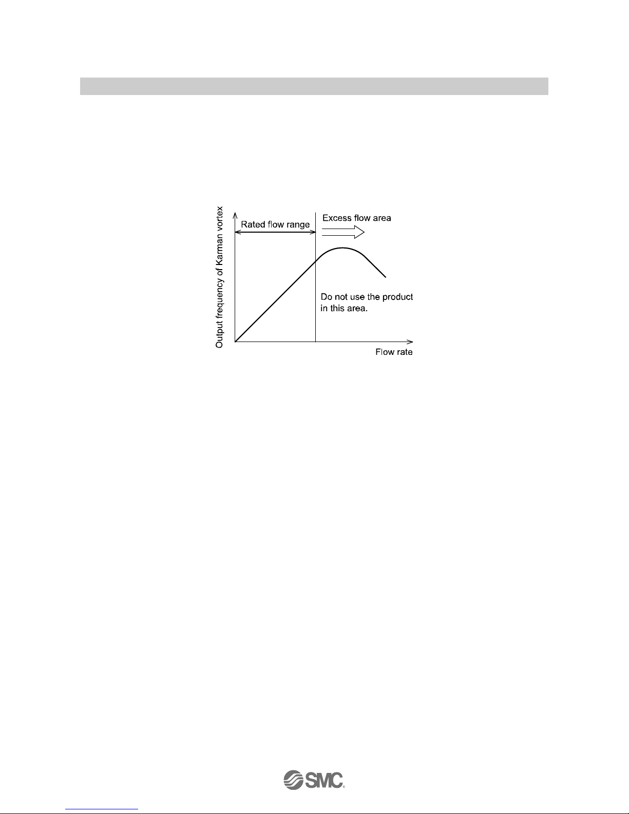
The product is a flow meter using Karman vortex. The flow meter using Karman vortex has lower output
frequency at excess flow state. Do not use the product within the excess flow area in the chart below.
Maintenance
Turn off the power supply, stop the fluid and check the safety before performing any maintenance.
There is a risk of unexpected malfunction.
Perform regular maintenance and inspections.
There is a risk of unexpected malfunction of components due to the malfunction of equipment and machinery.
Do not use solvents such as benzene, thinner etc. to clean the product.
They could damage the surface of the product and erase the indication on the product.
Use a soft cloth to remove stains. For heavy stains, use a cloth soaked with diluted neutral detergent and fully
squeezed, then wipe up the stains again with a dry cloth.

-10-
No.PF※※-OMN0010-J
Handling of flow adjustment valve
When flow is adjusted with the flow adjustment valve, do not apply excessive force to rotate it.
This can damage the valve mechanism.
When fixing the valve of the flow adjustment valve, do not apply excessive force to rotate the fixing knurl.
This can damage the knurl and valve mechanism.
After adjusting the flow, be sure to check that there is no water leakage.
After adjusting the flow, water leakage may occur due to the stability of the seal in the valve. If water leakage occurs,
open and close the valve several times to readjust it, and check that there is no water leakage.
The flow rate adjustment valve of this product is not suitable for applications which require constant
adjustment of flow rate.
Fluid leakage may be generated when the internal seal reaches the end of its life due to wearing.
Therefore, take measures to protect peripheral equipment, ensure maintenance space and pay
attention to the piping design.
The flow rate adjustment valve of this product is not suitable for applications which require reducing the
flow rate to zero completely. If it is necessary to reduce the flow rate to zero completely, install a stop
valve etc. separately.
Do not lift it by gripping the knob of the flow adjustment valve.
Hold the body when handling to avoid damaging the product.
If fluids with high temperature are flowed, the flow adjustment valve itself will also become hot, which
leads to a burn. Therefore, use the flow adjustment valve with special care.
Vinyl chloride piping
The vinyl chloride fitting (union) must be mounted and joined by an engineer with sufficient knowledge.
Be sure to confirm that there is no leakage from the fitting after mounting and joining. If it is mounted and joined by a
person who does not have sufficient knowledge and skills, it may lead to failure such as leakage.
When selecting adhesive for the vinyl chloride fitting (union), confirm that its heat resistance and
endurance are compatible with the operating temperature of the fluids used.
Otherwise, this may cause leakage and damage.
Do not apply excessive force to the vinyl chloride piping.
This may cause damage.
When the vinyl chloride piping type is used, the higher the fluid temperature, the lower the proof
pressure will be. Therefore, adjust the water hammer pressure carefully so that it does not exceed the
proof pressure.
-11-
No.PF※※-OMN0010-J
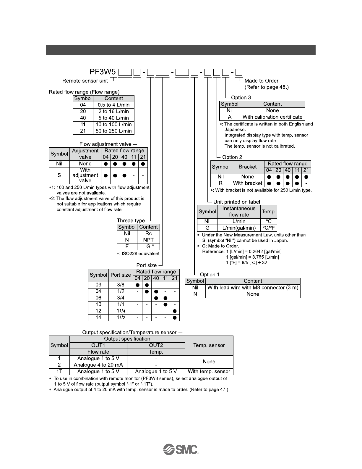
Model Indication and How to Order
●Metal piping
-12-
No.PF※※-OMN0010-J
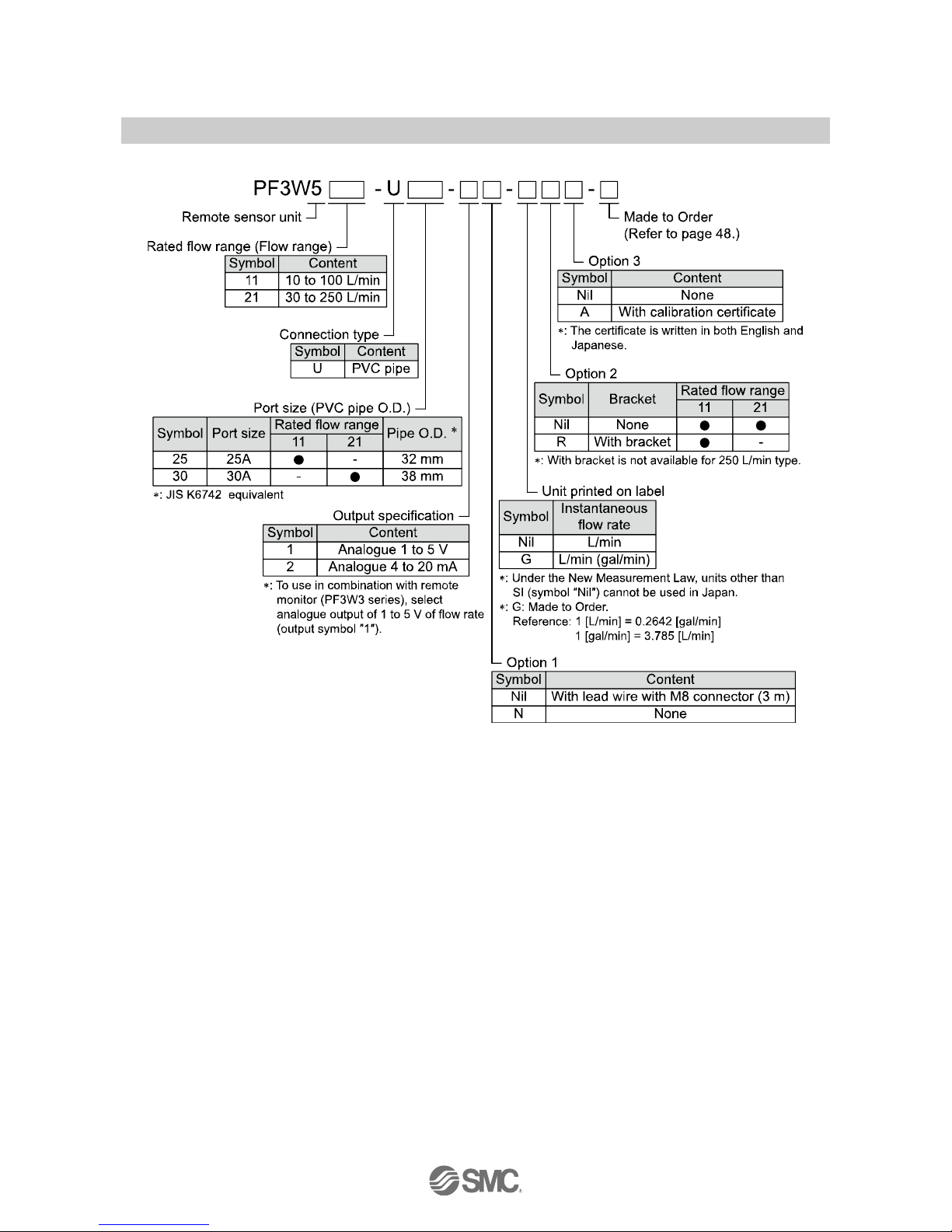
●Polyvinyl chloride piping
-13-
No.PF※※-OMN0010-J
Lead wire
NIL
N
With M8 connector and lead wire
With M8 connector and no lead wire
Bracket
NIL
R
Without bracket
With bracket
With flow adjustment valve
Options/Part number
If an option is required independently, order using the following part number.
Option
Part number
Remarks
Bracket
ZS-40-K
Taptite screw for PF3W504/520 (3 x 8), 4 pcs.
ZS-40-L
Taptite screw for PF3W540 (3 x 8), 4 pcs.
ZS-40-M
Taptite screw for PF3W511 (4 x 10), 4 pcs.
Lead wire with M8 connector
ZS-40-A
Lead wire length: 3 m
: 2 brackets are necessary if using the type with flow rate adjustment valve. Bracket cannot be mounted onto the 250 L/min type.
Replacement part
Element
Part number
Remarks
Vinyl chloride piping tube (25 A)
ZS-40-U25
25 A Vinyl chloride piping tube 1 pc.
Vinyl chloride piping tube (30 A)
ZS-40-U30
30 A Vinyl chloride piping tube e 1 pc.
25 A Holding plate
ZS-40-U25-A
1 pc., With two hexagon socket head cap screws of M5 x 80.
30 A Holding plate
ZS-40-U30-A
1 pc., With two hexagon socket head cap screws of M5 x 65.
: Accuracy may vary by 1 to 2%, if vinyl chloride piping tube is replaced.
-14-
No.PF※※-OMN0010-J
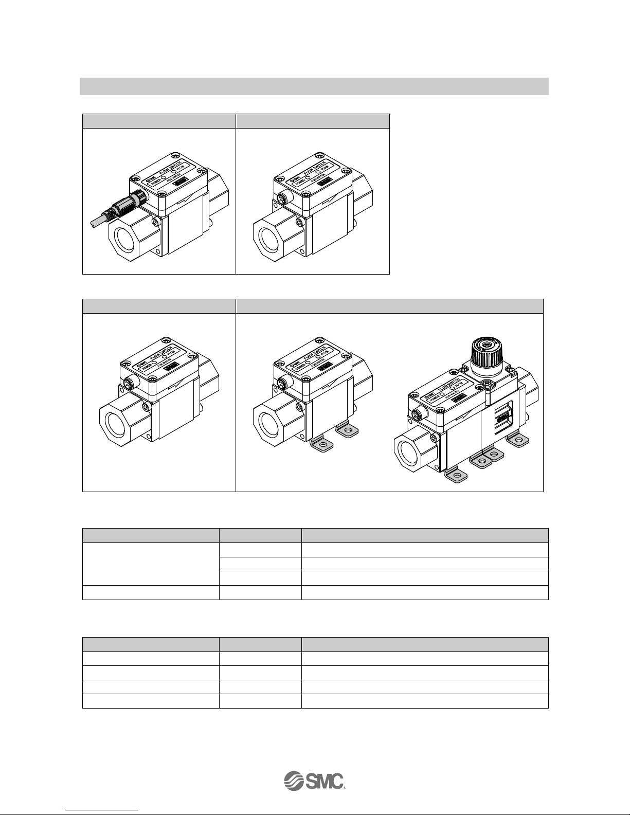
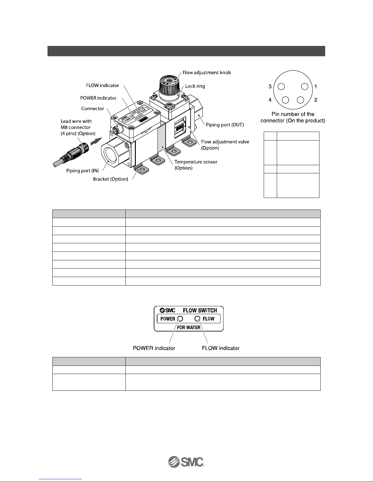
Summary of Product parts
Body
1
DC(+)
2
NC/Analogue
output
(temperature)
3
DC(-)
4
Analogue
output
(flow rate)
Element
Description
Connector
Connector for electrical connections.
Lead wire with M8 connector
Lead wire to supply power and transmit output signals.
Piping port
Port to connect the fluid inlet at IN and fluid outlet at OUT.
Bracket
Bracket for mounting the product.
Temperature sensor
Sensor for detecting the fluid temperature.
Flow adjustment valve
Restricting valve to adjust the flow rate.
Flow adjustment knob
Knob for adjusting the flow rate.
Lock ring
Ring for locking the flow adjustment valve.
Display
Element
Description
POWER indicator
Displays the power supply and error status and confirms product specifications.
FLOW indicator
Flashes at intervals proportional to the flow rate, and displays the error status.
The LED will be OFF when the flow is outside of the rated flow range.

-15-
No.PF※※-OMN0010-J
■Definition and terminology
Terms
Meaning
A
Analogue output
Outputs a value proportional to the flow rate. When the analogue output is in the range
1 to 5 V, it will vary between 1 to 5 V according to the rate of flow. The same for
analogue output of 4 to 20 mA.
Attachment
A metal part at both sides of the product to connect piping.
C
Cavitation
A phenomenon that may occur in a fluid moving at high speed. In the parts of the fluid
where the pressure is low, vapour bubbles form and then rapidly collapse. If cavitation
is present for a prolonged period, exposed surfaces will be damaged; this is called
cavitation damage or erosion.
F
F.S.
(Full span, Full scale)
Stands for "full span" or "full scale", and indicates varied display valve and analogue
output range at rated value. For example, when analogue output is 1 to 5 V, F.S. = 5[V]
- 1[V] = 4[V], (ref. 1%F.S. = 4[V] x 1% = 0.04[V])
FLOW indicator
Used to determine the flow rate status visually. The higher the flow rate, the faster the
flashing speed will be. (It may display an error.)
Fluid temperature
Range of fluid temperature that can be measured by the product.
I
Instantaneous flow
The flow passing per unit of time. If it is 10 L/min, there is a flow of 10 L passing through
the device in 1 minute.
K
Karman vortex
When an object is placed in a fluid stream, a vortex will be created in the fluid on the
downstream side. This vortex is called a Karman vortex. The frequency at which the
vortices are generated is proportional to the fluid velocity, therefore it is possible to
calculate the fluid flow rate by measuring the Karman vortex frequency.
M
Measured fluid
The fluid(s) that the product can measure.
O
Operating pressure
range
Pressure range in which product is operable.
Operating temp. range
Ambient temperature range in which product is operable.
P
Part in contact with
fluid (wetted part)
A part that comes into physical contact with the fluid.
POWER indicator
Used to confirm the power supply status. It turns on when the power supply is applied.
(It may display the output specification)
Pressure
characteristics
Indicates the change in the display value and analogue output when fluid pressure
changes.
Proof pressure
Burst pressure at which the product is electrically or mechanically damaged.
R
Rated flow range
The flow range within which the product will meet all published specifications.
Rated pressure range
The pressure range that satisfies the specifications.
Repeatability
Reproducibility of the display or analogue output value, when the measured quantity is
repeatedly increased and decreased.
Response time
Time from when the target flow is applied until the flow reaches 90% of the set value.
T
Temperature
characteristics
Indicates the change in the display value and analogue output caused by ambient
temperature changes.
U
Union
Fitting which is connected to the vinyl chloride piping (tube piping).
W
Water hammer
A pressure surge occurring when a moving fluid is forced to stop or change direction
suddenly. Water hammer often occurs when a valve is closed suddenly, and a pressure
wave propagates in the pipe.

-16-
No.PF※※-OMN0010-J
Mounting and Installation
Installation
Use the product within the specified operating pressure and temperature range.
Proof pressure could vary according to the fluid temperature. Check the characteristics data for operating
pressure and proof pressure.
Mounting
Never mount the product in a location where it will be used as a support.
Mount the product so that the fluid flows in the direction indicated by the arrow on the side of the body.
Check the flow characteristics data for pressure loss and the straight inlet pipe length effect on accuracy
(page 36), to determine inlet piping requirements.
Do not sharply reduce the piping size.

-17-
No.PF※※-OMN0010-J
■Installation
Bracket mounting (PF3W504/520/540)
Mount the product (with bracket) using the mounting
screws supplied (M4 x 4 pcs.).
For models with flow adjustment valve attached, fix using
8 mounting screws.
Bracket thickness is approx. 1.5 mm.
Refer to the outline dimension drawing (page 41) for
mounting hole size.
Bracket mounting (PF3W511)
Mount the product (with bracket) using
the mounting screws supplied
(M5 x 4 pcs.).
The thickness of the bracket plate is
approx. 2 mm.
Refer to the outline dimension drawing
(page 41) for mounting hole size.

-18-
No.PF※※-OMN0010-J
Direct mounting (PF3W504/520/540)
Mount using the self tapping screws
(nominal size: 3.0 x 4 pcs.) for
installation.
For models with flow adjustment valve
attached, mount using 8 self tapping
screws.
The tightening torque must be 0.5 to
0.7 Nm.
Refer to the outline dimension drawing
(page 41) for mounting hole dimensions.
The self tapping screws should not be
re-used.
Direct mounting (PF3W511/521)
Mount using the self tapping screws (nominal size: 4.0 x 4 pcs.) for installation.
The tightening torque must be 1.0 to 1.2 Nm.
Refer to the outline dimension drawing (page 41) for mounting hole dimensions.
The self tapping screws should not be re-used.

-19-
No.PF※※-OMN0010-J
■Piping
When connecting piping to the product, a spanner should be used on the metal piping attachment only.
Using a spanner on other parts may damage the product.
In particular, do not let the spanner come into contact with the M8 connector.
The connector can be easily damaged.
Width across flats of attachment
3/8
24 mm
1/2
27 mm
3/4
32 mm
1
41 mm
11/4
54 mm
11/2
54 mm
Tighten to the specified torque for piping.
The tightening torque for connection threads is shown in the table below.
Nominal thread size
Tightening torque
Rc(NPT)3/8
22 to 24 Nm
Rc(NPT)1/2
28 to 30 Nm
Rc(NPT)3/4
28 to 30 Nm
Rc(NPT)1
36 to 38 Nm
Rc(NPT)11/4
40 to 42 Nm
Rc(NPT)11/2
48 to 50 Nm
If the tightening torque is exceeded, the product can be broken. If the correct tightening torque is not
applied, the fittings may become loose.
Avoid any sealing tape getting inside the piping.
Ensure there is no leakage from loose piping.

-20-
No.PF※※-OMN0010-J
Caution
The product body is made of resin. The installation and piping of the product must satisfy the following
requirements.
This may cause damage, breakage and/or water leakage of the product.
•No load should be directly applied to the product.
•Do not install piping to the product with a misalignment.
A permanent load will be applied to the product after piping.
•When a flexible hose is used for the piping, the hose must be fixed with a bracket etc.
If it is not fixed, the load weight of the flexible hose and the fluid will be applied to the product.
Caution
Vinyl chloride piping
Mounting and joining of the vinyl chloride fitting (union)
The vinyl chloride fitting (union) must be mounted and joined
by an engineer with sufficient knowledge. Be sure to confirm
that there is no leakage from the fitting after mounting and
joining. If it is mounted and joined by a person who does not
have sufficient knowledge and skills, it may lead to failure
such as leakage.
When selecting adhesive for the vinyl chloride fitting
(union), confirm that its heat resistance and endurance
are compatible with the operating temperature of the
fluids used.
Otherwise, this may cause leakage and damage.

-21-
No.PF※※-OMN0010-J
How to adjust the flow rate (when a flow adjustment valve is mounted)
(1) Rotate the knob of the valve to adjust the flow rate to the target value.
(2) Be sure to confirm that there is no fluid leakage generated after adjustment.
(When fluid leakage is generated, open and close the valve several times for re-adjustment, and confirm
that there is no fluid leakage.)
(3) Tighten the lock ring to fix the valve as necessary.
The flow adjustment valve is not designed for applications that require daily and repetitive adjustment.
If the valve is adjusted frequently, fluid may leak due to wear of the internal seal.

-22-
No.PF※※-OMN0010-J
■Wiring
Wiring of connector
Connections should only be made with the power supply turned off.
Use separate routes for the Flow sensor wiring and any power or high voltage wiring. Otherwise,
malfunction may result due to noise.
Ensure that the FG terminal is connected to ground when using a commercially available switch-mode
power supply. When a switch-mode power supply is connected to the product, switching noise will be
superimposed and the product specification can no longer be met. This can be prevented by inserting a
noise filter, such as a line noise filter and ferrite core, between the switch-mode power supply and the
product, or by using a series power supply instead of a switch-mode power supply.
Pin No.
Description
Wire colour
1
DC(+)
Brown
2
N.C. / Tem. analogue output (1 to 5 V)
White
3
DC(-)
Blue
4
Flow analogue output (1 to 5 V, 4 to 20 mA)
Black
: When using the lead wire with M8 connector included with the PF3W5 series.
Tighten the connector by hand.
Examples of Internal Circuit and Wiring
1 to 5 V / 4 to 20 mA output type
PF3W5--1/2
With temperature sensor 1 to 5 V output type
PF3W5--1T
Analogue output 1 to 5 V
Output impedance: 1 k
Analogue output 4 to 20 mA
Maximum load impedance
Power supply voltage 12 V: 300
Power supply voltage 24 V: 600
Analogue output 1 to 5 V
Output impedance: 1 k

-23-
No.PF※※-OMN0010-J
Flow Measurement
Measurement mode
The mode in which the flow is detected and the flow indicator flashes, and analogue output is operating.
: Green: Flashes once. PF3W5□-□-1 (Analogue 1 to 5 V type: Without temperature sensor)
Flashes twice. PF3W5□-□-2 (Analogue 4 to 20 mA type: Without temperature sensor)
Flashes three times. PF3W5□-□-1T (Analogue 1 to 5 V type: With temperature sensor)
The power LED (Green) turns on and the flow rate indicator flashes according to the flow rate.

-24-
No.PF※※-OMN0010-J
Maintenance
How to reset the product after a power cut or when the power has been unexpectedly removed
The output condition also recovers to that before the power cut or de-energizing, but may change depending
on the operating environment.
Therefore, check the safety of the whole system before operating the product.

-25-
No.PF※※-OMN0010-J
Troubleshooting
Troubleshooting
Applicable Flow sensor: PF3W5 series
If an operation failure occurs with the product, use the chart below to find out the cause of problem.
If a cause applicable to the failure cannot be identified and normal operation can be recovered by
replacement with a new product, this indicates that the product itself was faulty. The damage to the product
may have been caused by operating environment (network construction, etc.). Consult with SMC separately
to obtain countermeasures.
Cross-reference for troubleshooting
Fault
Detail
Possible cause
Item to check
Recommended action
Incorrect
output
No output
Incorrect wiring
Check if the brown wire DC(+), blue
wire DC(-), black wire(OUT1) and white
wire(OUT2) are connected correctly.
Correct the wiring.
Loose connector
Check that the connector is connected.
Connect the connector.
The flow
adjustment valve
is closed.
Check the condition of the flow
adjustment valve.
Open the flow adjustment
valve to get appropriate
flow.
Output is
unstable.
Foreign matter
has entered or got
stuck inside the
flow passage of
the sensor.
(1) Confirm whether foreign matter may
enter.
(2) Confirm whether any foreign matter
has got stuck inside.
We recommend a filter with
filtration of approx. 40
mesh.
Remove foreign matter.
Piping is
connected in the
wrong direction.
Confirm whether the mounting direction
of the product corresponds to the flow
direction.
Make the mounting
direction correspond to the
flow direction.
Insufficient water
supply
Confirm whether the fluid path is full.
Fill up the fluid path.
Pulsation in the
flow.
Confirm whether the supply pressure
fluctuates, or whether pulsation is
generated due to the characteristics of
the compressor or pump used as the
pressure source.
Change to a pump that has
less pulsation. Install a tank
to reduce the pressure
fluctuation. Change the
piping to elastic piping such
as rubber hose.
Liquid leakage
Check for liquid leaks due to insufficient
tightening of the screw at the piping
and/or improper sealing.
Tighten to the specified
torque when piping and/or
apply the seal tape once
again.
Noise
Confirm that there is no power line or
high voltage line that can be a noise
source in the wiring route.
Do not route wires and
cables together with power
or high voltage cables.
Even though
the flow rate
is zero, it is
outputted.
Operation of
pump while the
flow adjustment
valve is closed.
Check the condition of the flow
adjustment valve and pump.
Open the flow adjustment
valve slightly, and let the
pulsation (pressure) from
the pump escape.

-26-
No.PF※※-OMN0010-J
Fault
Detail
Possible cause
Item to check
Recommended action
Incorrect
indicator
The indicator
does not turn
on.
Incorrect wiring
Check if the brown wire DC(+) and blue
wire DC(-) are connected correctly.
Correct the wiring.
The FLOW
indicator is
unstable.
Foreign matter
has entered or got
stuck inside the
flow passage of
the sensor.
(1) Confirm whether foreign matter may
enter.
(2) Confirm whether any foreign matter
has got stuck inside.
We recommend a filter with
filtration of approx. 40
mesh.
Remove foreign matter.
Piping is
connected in the
wrong direction.
Confirm whether the mounting direction
of the product corresponds to the flow
direction.
Make the mounting
direction correspond to the
flow direction.
Insufficient water
supply
Confirm whether the fluid path is full.
Fill up the fluid path.
Pulsation in the
flow.
Confirm whether the supply pressure
fluctuates, or whether pulsation is
generated due to the characteristics of
the compressor or pump used as the
pressure source.
Change to a pump that has
less pulsation. Install a tank
to reduce the pressure
fluctuation. Change the
piping to elastic piping such
as rubber hose.
Noise
Confirm that there is no power line or
high voltage line that can be a noise
source in the wiring route.
Do not route wires and
cables together with power
or high voltage cables.
Incorrect
temp.
sensor
output.
Output is
unstable.
Insufficient water
supply
Confirm whether the fluid path is full.
Fill up the fluid path.
Foreign matter
Check if foreign matter is stuck to the
sensor.
Remove foreign matter.
Improper
operation
of the flow
adjustment
valve.
It is not
possible to
adjust with
flow
adjustment
valve.
Lock the flow
adjustment valve
Check the condition of the flow
adjustment valve and its lock ring.
Loose the lock ring and
adjust flow rate. (Refer to
page 21.)
Insufficient supply
pressure
Check flow rate characteristics of the
supply pressure and flow rate
adjustment valve.
Increase supply pressure.

-27-
No.PF※※-OMN0010-J
Error indication function
Error Name
LED display
Type
Troubleshooting
Flow rate upper
limit is exceeded
POWER indicator: Green is ON
FLOW indicator: Red is ON
The applied flow rate is above
approx. 110% of maximum rated
flow rate.
Adjust flow to within the
rated flow range.
Outside the
temperature
measurement
range
POWER indicator: Flashing Red
The fluid temperature is lower
than -10oC or exceeds 110oC.
Adjust the fluid
temperature to within the
rated temperature range.
"Flow rate upper
limit exceeded"
and "Outside the
temperature
measurement
range" occur
together.
POWER indicator: Flashing Red
FLOW indicator: Red is ON
See above.
See above.
System error
POWER indicator: Red is ON
FLOW indicator: Red is ON
Internal data error has occurred.
Turn the power off and
turn it on again. If the
failure cannot be solved,
contact SMC for repair.
POWER indicator: Red is ON
FLOW indicator: Flashing Red
POWER indicator: Red is ON
FLOW indicator: OFF
The temperature sensor is
damaged.
If the error cannot be reset after the above measures are taken, then please contact SMC

-28-
No.PF※※-OMN0010-J
Specification
■Specifications
Specifications of body (Metal attachment)
Model
PF3W504
PF3W520
PF3W540
PF3W511
PF3W521
Applicable fluid
Water and ethylene glycol solution with a viscosity of 3 mPas(3 cP) or less 1
Detecting method
Karman vortex
Rated flow range
0.5 to 4 L/min
2 to 16 L/min
5 to 40 L/min
10 to 100 L/min
50 to 250 L/min
Fluid temperature
0 to 90 oC (No freezing and condensation)
0 to 70 oC (No
freezing and
condensation)
Accuracy
±3% F.S. max.
Repeatability
±2% F.S. max.
Temperature
characteristics
±5% F.S. max. (reference 25 oC)
Operating pressure range
2
Refer to graph of operating pressure and proof pressure
Proof pressure 2
Refer to graph of operating pressure and proof pressure
Pressure loss
Refer to graph of pressure loss
Analogue
output
Response
time 3
1 s
Voltage output
Output voltage: 1 to 5 V, Output impedance: 1 kΩ
Current
output
Current output: 4 to 20 mA
Maximum load impedance: 300 Ω for 12 VDC, 600 Ω for 24 VDC
Indicator light
LED for power supply,
LED for flow rate indicator (Flashing speed changes depending on the flow rate.),
LED for other error display
Power supply voltage
12 to 24 VDC ±10%
Current consumption
30 mA max.
Environment
Enclosure
IP65
Operating
temperature
range
0 to 50 oC (No freezing and condensation)
Operating
humidity
range
Operation, Storage: 35 to 85% R.H. ( No condensation)
Withstand
voltage 4
1000 VAC, for 1 minute between the terminals and housing
Insulation
resistance
50 MΩ min. (with 500VDC) between the terminals and housing
Standards and
regulations
CE marking, UL(CSA), RoHS
Wetted materials
PPS, SUS304, FKM, SCS13
PPS, SUS304,
FKM
Non-grease type
Piping port size 5
3/8
3/8, 1/2
1/2, 3/4
3/4, 1
11/4, 11/2

-29-
No.PF※※-OMN0010-J
Model
PF3W504
PF3W520
PF3W540
PF3W511
PF3W521
Weight
Flow sensor
only
195 g
245 g
395 g
705 g
875 g
With
temperature
sensor
270 g
320 g
515 g
840 g
1060 g
With flow
adjustment
valve
295 g
345 g
595 g - -
With
temperature
sensor and
flow
adjustment
valve
370 g
415 g
715 g - -
With lead wire
+85 g
1: Please refer to the chart of measurement range of ethylene glycol aqueous solution on page 32. Measurement is possible as long as
the fluid does not corrode the wetted parts, and viscosity is 3 mPas(3 cP) or less. Be aware that water leakage may happen due to
internal seal shrinkage or swelling depending on kinds of fluid. Refer to the "Applicable fluid list" on page 31.
2: The operating pressure range and proof pressure vary depending on the fluid temperature. Refer to the chart on page 35.
3: The response time is when the set value is 90% in relation to the step input. (The value will be 7 s for the temperature sensor output.)
4: When the temperature sensor is used, it will be 250 VAC.
5: If a reduced piping diameter or the piping layout cause a restriction, it may not satisfy the specifications.
: The form of the G thread (including the major and minor diameter and pitch of the internal thread) is based on JIS B0202 (ISO228-1).
Products indicated as ISO1179-1 (G thread for hydraulics) or ISO16030 (G thread for pneumatics) are based on JIS B0202
(ISO228-1) for effective depth of thread, seat surface area, surface roughness and squareness.
For ISO1179-1 (G thread for hydraulics), the withstand pressure is specified for each product. SMC do not guarantee the withstand
pressure specified in ISO1179-1, ISO1179-2, ISO1179-3, or ISO1179-4.
For ISO16030 (G thread for pneumatics), the withstand pressure is specified for each product. SMC do not guarantee the withstand
pressure specified in ISO16030.
Specifications of temperature sensor
Items
Specifications
Rated temperature range
0 to 100 oC 1
Analogue output accuracy
±3% F.S.
Response time
7 s 2
Ambient temperature characteristics
±5% F.S.
1: The rated temperature range is of a single temperature sensor. As a whole product, the fluid temperature range is specified as 0 to
90 oC.
2: The response time is only for the temperature sensor.

-30-
No.PF※※-OMN0010-J
Specifications of body (Vinyl chloride piping)
Model
PF3W511
PF3W521
Applicable fluid
Water and ethylene glycol solution with a viscosity of 3 mPas(3 cP) or less 1
Detecting method
Karman vortex
Rated flow range
10 to 100 L/min
30 to 250 L/min
Fluid temperature
0 to 70 oC (No freezing and condensation)
Accuracy
±3% F.S. max.
Repeatability
±2% F.S. max.
Temperature
characteristics
±5% F.S. max. (reference 25 oC)
Operating pressure
range 2
Refer to graph of operating pressure and proof pressure
Proof pressure 2
Refer to graph of operating pressure and proof pressure
Pressure loss
Refer to graph of pressure loss
Analogue
output
Response
time 3
1 s
Voltage
output
Output voltage: 1 to 5 V, Output impedance: 1 kΩ
Current
output
Current output: 4 to 20 mA
Maximum load impedance: 300 Ω for 12 VDC, 600 Ω for 24 VDC
Indicator light
LED for power supply,
LED for flow rate indicator (Flashing speed changes depending on the flow rate.),
LED for other error display
Power supply voltage
12 to 24 VDC ±10%
Current consumption
30 mA max.
Environment
Enclosure
IP65
Operating
temperature
range
0 to 50 oC (No freezing and condensation)
Operating
humidity
range
Operation, Storage: 35 to 85% R.H. ( No condensation)
Withstand
voltage
1000 VAC, for 1 minute between the terminals and housing
Insulation
resistance
50 MΩ min. (with 500 VDC) between the terminals and housing
Standards and
regulations
CE marking, UL(CSA), RoHS
Wetted materials
PPS, FKM, CPVC
Non-grease type
Piping port size 4
25A union
30 A
Weight
Without lead
wire
270 g
325 g
With lead
wire
355 g
410 g
1: Please refer to the chart of measurement range of ethylene glycol aqueous solution on page 32. Measurement is possible as long as
the fluid does not corrode the wetted parts, and viscosity is 3 mPas (3 cP) or less. Be aware that water leakage may happen due to
internal seal shrinkage or swelling depending on kinds of fluid. Refer to the "Applicable fluid list" on page 31.
2: The operating pressure range and proof pressure vary depending on the fluid temperature. Refer to the chart on page 35.
3: The response time is when the set value is 90% in relation to the step input.
4: If a reduced piping diameter or the piping layout cause a restriction, it may not satisfy the specifications.

-31-
No.PF※※-OMN0010-J
●Applicable fluids of vinyl chloride piping tube
The material and fluids compatibility check list
Chemical
Compatibility
Ammonium hydroxide
x
Isobutyl alcohol
x 3
Isoproply alcohol
○
12
Hydrochloric acid
(Except fuming sulfuric acid)
Concentration 30% or less
○ 2
Hydrogen peroxide
Concentration 5% or less
○
Nitric acid
(Except fuming nitric acid)
Concentration 10% or less
○ 2
Pure water
○
Sodium hydroxide
Concentration 50% or less
x
3
Pure water
○
Sulfuric acid
Concentration 30% or less
○
Phosphonic acid
Concentration 50% or less
○
○: Available (available depending on the conditions)
The material and fluid compatibility check list provides reference values for reference only,
therefore we do not guarantee the application to our product.
1: Take measures against static electricity, which it may occur.
2: Fluid may be permeated, affecting other material parts.
3: Because fluid viscosity is high, it cannot be measured by the Karman vortex method.
SMC is not responsible for its accuracy and any damage happened because of this data.
Specifications: lead wire with M8 connector (ZS-40-A)
Items
Specifications
Conductor
Nominal cross section area
AWG23
Outside diameter
Approx. 0.72 mm
Insulator
Outside diameter
Approx. 1.14 mm
Colours
Brown, White, Black, Blue
Sheath
Outer diameter
3.4 mm

-32-
No.PF※※-OMN0010-J
■Characteristics graph
Measurable range of ethylene glycol aqueous solution (Reference value)

-33-
No.PF※※-OMN0010-J
Flow characteristics (pressure loss)
PF3W504
PF3W520
PF3W540
PF3W511 (Metal attachment)
PF3W521 (Metal attachment)

-34-
No.PF※※-OMN0010-J
PF3W511 (Vinyl chloride piping)
PF3W521 (Vinyl chloride piping)

-35-
No.PF※※-OMN0010-J
Operating pressure and proof pressure
PF3W504/520/540
PF3W504S/520S/540S
PF3W511 (Metal attachment)
PF3W521 (Metal attachment)
PF3W511/521 (Vinyl chloride piping)

-36-
No.PF※※-OMN0010-J
Straight inlet pipe length and accuracy (reference value)
Metal attachment
The smaller the piping size, the more the product is affected by the straight piping length.
Fluid pressure has almost no effect.
The smaller the flow rate, the less the product is affected by the straight piping length.
The straight piping length shall be 8 cm or longer in order to maintain ±3%F.S. of the specification.
(For the 100 L/min and 250 L/min types, the piping length should be 11 cm or longer.)
PF3W504
PF3W520
PF3W540
PF3W511 (Metal attachment)

-37-
No.PF※※-OMN0010-J
PF3W521 (Metal attachment)

-38-
No.PF※※-OMN0010-J
Vinyl chloride piping
Fluid pressure has almost no effect.
The straight piping length shall be 11 cm or longer in order to maintain ±3%F.S. of the specification.
PF3W511/521 (Vinyl chloride piping)

-39-
No.PF※※-OMN0010-J
Flow characteristics of the flow rate adjustment valve
PF3W504S
PF3W520S
PF3W540S

-40-
No.PF※※-OMN0010-J
■Analogue output
Analogue output (Flow)
(PF3W504/520/540)
A B
C
Voltage output
1 V
1.5 V
5 V
Current output
4 mA
6 mA
20 mA
(PF3W511)
A B
C
Voltage output
1 V
1.4 V
5 V
Current output
4 mA
5.6 mA
20 mA
(PF3W521-12/14)
A B C Voltage output
1 V
1.8 V
5 V
Current output
4 mA
7.2 mA
20 mA
(PF3W521-U30)
A B C Voltage output
1 V
1.48 V
5 V
Current output
4 mA
5.92 mA
20 mA
Sensor model
Rated flow [L/min]
Minimum
Maximum
PF3W504
0.5
4
PF3W520
2
16
PF3W540
5
40
PF3W511
10
100
PF3W521-12/14
50
250
PF3W521-U30
30
250
Analogue output (Fluid temperature)
A B C D
Voltage
output
0.6 V
1 V
5 V
5.4 V

-41-
No.PF※※-OMN0010-J
■Dimensions
PF3W504/520/540/511
Basic type
Symbol
Piping port
size
A
AA B DD E F G H J K L N
P
Model
PF3W504
3/8
70
50
30
45.6
40.6
15.2
24
14
35
26
18
13.6
2.7 depth 14
PF3W520
3/8, 1/2
78
54
30
45.6
40.6
15.2
27
18
39
30
18
13.6
2.7 depth 12
PF3W540
1/2, 3/4
98
71
38
53.6
48.6
19.2
32
28
49
35
28
16.8
2.7 depth 12
PF3W511
3/4, 1
124
92
46
62.6
57.6
23
41
42
63
48
28
18
3.5 depth 14
Symbol
Bracket dimensions
Model S T U V W WX Y Z
PF3W504
24
22
32
40
50
4.5 5 1.5
PF3W520
28
22
32
40
50
4.5 5 1.5
PF3W540
34
30
42
48
58
4.5 5 1.5
PF3W511
44
36
48
58
70
5.5 7 2

-42-
No.PF※※-OMN0010-J
PF3W521
Basic type
Symbol
Piping port
size
A
AA B DD E F G H J K L N
P
Model
PF3W521
11/4, 11/2
104
74
56
76.6
71.6
28.5
54
31
52
39.5
25
27.5
3.5 depth 14
G 11/4
108
76
33
54
41.5
G 11/2
112
78
35
56
43.5

-43-
No.PF※※-OMN0010-J
PF3W504/520/540/511/521 (With temperature sensor)
Temperature sensor
Symbol
A
AA
Model
PF3W504--T
81
50
PF3W520--T
89
54
PF3W540--T
109
71
PF3W511--T
135
92
PF3W521-□-□T
115
74
PF3W521-F12-□T
119
76
PF3W521-F14-□T
123
78

-44-
No.PF※※-OMN0010-J
PF3W504/520/540 (With flow adjustment valve)
Basic type and flow adjustment valve
Symbol
A
AA B D F K L N P Q
Q: Number
of rotations
Model
PF3W504S
104
50
63.6 (Max. 68.6)
70.2
34
58.5
18
13.6
2.7 depth 10
19
6 turns
PF3W520S
112
54
63.6 (Max. 68.6)
74.2
34
62.5
18
13.6
2.7 depth 10
19
6 turns
PF3W540S
142
71
75.25 (Max. 81)
94.5
44
79
28
16.8
2.7 depth 10
28
7 turns
Symbol
Bracket dimensions
Model S T
PF3W504S
56.5
22
PF3W520S
60.5
22
PF3W540S
78
30

-45-
No.PF※※-OMN0010-J
PF3W504/520/540 (With temperature sensor and flow adjustment valve)
Basic type and flow adjustment valve and temperature sensor
Symbol
A
AA D K
S
Model
PF3W504S--T
115
50
81.2
69.5
67.5
PF3W520S--T
123
54
85.2
73.5
71.5
PF3W540S--T
153
71
105.5
90
89

-46-
No.PF※※-OMN0010-J
PF3W511-U25/PF3W521-U30 (Vinyl chloride piping)
Piping port
A B D E F J K L N P Q
25 A
154
46
77
57.6
23
77
63
28
18
3.5 depth 14
32
32 A
146
56
91
71.6
28.5
73
60.5
25
27.5
3.5 depth 14
38
Piping port
Bracket dimensions
S T U V W Y Z
25 A
59
36
48
58
70 7 2

-47-
No.PF※※-OMN0010-J
Dimensions of lead wire with M8 connector (ZS-40-A)

-48-
No.PF※※-OMN0010-J
Made to Order
●Change the seal material of the wetted parts to EPDM.
Refer to page 11 for details of how to order.
●Change the material of the piping port to brass.
Refer to page 11 for details of how to order.
: Not applicable to the vinyl chloride piping type.
: Not applicable to the flow rate adjustment valve mounted type. Can be done as a special order.
●2 analogue outputs (4 to 20 mA)
Refer to page 11 for details of how to order.
: Not applicable to the vinyl chloride piping type.

No.PF※※-OMN0010-J
Revision history
A: Add the product model.
B: Contents are added.
C: Contents are added.
D: Contents revised in several places.
E: Contents are added.
F: Contents are added.
G: Contents revised in several places.
H: Contents are added.
I: Contents revised in several places.[March 2017]
J: Contents revised in several places. [July 2018]
4-14-1, Sotokanda, Chiyoda-ku, Tokyo 101-0021 JAPAN
Tel: + 81 3 5207 8249 Fax: +81 3 5298 5362
URL http://www.smcworld.com
Note: Specifications are subject to change without prior notice and any obligation on the part of the manufacturer.
© 2011-2018 SMC Corporation All Rights Reserved
 Loading...