

SMC Networks PF2M7 Series, PF2M725, PF2M750, PF2M710, PF2M711 Operation Manual
No.PF※※-OMW0007-A
PRODUCT NAME
Digital Flow Switch
(Integrated display type)
MODEL / Series / Product Number
PF2M7##

-1-
No.PF※※-OMW0007-A
Table of Contents
Safety Instructions 2
Model Indication and How to Order 10
Summary of Product parts 13
Definition and terminology 14
Mounting and Installation 17
Installation 17
Wiring 19
Outline of Settings 22
Flow Setting 23
Simple Setting Mode 24
Function Setting 25
Default setting 26
F0 Fluid/Unit criteria/Measurement unit setting 27
F1 Setting of OUT1 29
F2 Setting of OUT2 34
F3 Digital filter setting 38
F4 Auto-preset function setting 39
F10 Display mode setting 41
F11 Display resolution setting 42
F13 Setting for reverse display mode 43
F14 Zero cut-off setting 44
F22 Analogue output and analogue free span function setting 45
F30 Accumulated flow value hold setting 47
F80 Display OFF mode setting 48
F81 Security code 49
F90 Setting of all functions 50
F98 Setting of output check 52
F99 Reset to the default settings 54
Other Settings 55
Maintenance 61
Forgotten the security code 61
Troubleshooting 62
Error indication 65
Specifications 66
Characteristics data 69
Dimensions 73
-2-
No.PF※※-OMW0007-A
Safety Instructions
These safety instructions are intended to prevent hazardous situations and/or equipment damage.
These instructions indicate the level of potential hazard with the labels of "Caution", "Warning" or "Danger".
They are all important notes for safety and must be followed in addition to International Standards
(ISO/IEC)*1), and other safety regulations.
*1) ISO 4414: Pneumatic fluid power -- General rules relating to systems.
ISO 4413: Hydraulic fluid power -- General rules relating to systems.
IEC 60204-1: Safety of machinery -- Electrical equipment of machines. (Part 1: General requirements)
ISO 10218: Manipulating industrial robots -Safety.
etc.
Caution
Caution indicates a hazard with a low level of risk which, if not avoided, could
result in minor or moderate injury.
Warning
Warning indicates a hazard with a medium level of risk which, if not avoided,
could result in death or serious injury.
Danger
Danger indicates a hazard with a high level of risk which, if not avoided, will
result in death or serious injury.
Warning
1. The compatibility of the product is the responsibility of the person who designs the
equipment or decides its specifications.
Since the product specified here is used under various operating conditions, its compatibility with specific
equipment must be decided by the person who designs the equipment or decides its specifications
based on necessary analysis and test results.
The expected performance and safety assurance of the equipment will be the responsibility of the person
who has determined its compatibility with the product.
This person should also continuously review all specifications of the product referring to its latest catalog
information, with a view to giving due consideration to any possibility of equipment failure when
configuring the equipment.
2. Only personnel with appropriate training should operate machinery and equipment.
The product specified here may become unsafe if handled incorrectly.
The assembly, operation and maintenance of machines or equipment including our products must be
performed by an operator who is appropriately trained and experienced.
3. Do not service or attempt to remove product and machinery/equipment until safety is
confirmed.
1. The inspection and maintenance of machinery/equipment should only be performed after measures to
prevent falling or runaway of the driven objects have been confirmed.
2. When the product is to be removed, confirm that the safety measures as mentioned above are
implemented and the power from any appropriate source is cut, and read and understand the specific
product precautions of all relevant products carefully.
3. Before machinery/equipment is restarted, take measures to prevent unexpected operation and malfunction.
4. Contact SMC beforehand and take special consideration of safety measures if the
product is to be used in any of the following conditions.
1. Conditions and environments outside of the given specifications, or use outdoors or in a place
exposed to direct sunlight.
2. Installation on equipment in conjunction with atomic energy, railways, air navigation, space, shipping,
vehicles, military, medical treatment, combustion and recreation, or equipment in contact with food and
beverages, emergency stop circuits, clutch and brake circuits in press applications, safety equipment or
other applications unsuitable for the standard specifications described in the product catalog.
3. An application which could have negative effects on people, property, or animals requiring special
safety analysis.
4. Use in an interlock circuit, which requires the provision of double interlock for possible failure by using
a mechanical protective function, and periodical checks to confirm proper operation.
-3-
No.PF※※-OMW0007-A
Safety Instructions
Caution
1.The product is provided for use in manufacturing industries.
The product herein described is basically provided for peaceful use in manufacturing industries.
If considering using the product in other industries, consult SMC beforehand and exchange
specifications or a contract if necessary.
If anything is unclear, contact your nearest sales branch.
Limited warranty and Disclaimer/Compliance Requirements
The product used is subject to the following "Limited warranty and Disclaimer" and "Compliance
Requirements".
Read and accept them before using the product.
Limited warranty and Disclaimer
1. The warranty period of the product is 1 year in service or 1.5 years after the product is
delivered, whichever is first.2)
Also, the product may have specified durability, running distance or replacement parts.
Please consult your nearest sales branch.
2. For any failure or damage reported within the warranty period which is clearly our
responsibility, a replacement product or necessary parts will be provided.
This limited warranty applies only to our product independently, and not to any other
damage incurred due to the failure of the product.
3. Prior to using SMC products, please read and understand the warranty terms and
disclaimers noted in the specified catalog for the particular products.
2) Vacuum pads are excluded from this 1 year warranty.
A vacuum pad is a consumable part, so it is warranted for a year after it is delivered.
Also, even within the warranty period, the wear of a product due to the use of the
vacuum pad or failure due to the deterioration of rubber material are not covered by the
limited warranty.
Compliance Requirements
1. The use of SMC products with production equipment for the manufacture of weapons of
mass destruction (WMD) or any other weapon is strictly prohibited.
2. The exports of SMC products or technology from one country to another are governed by
the relevant security laws and regulation of the countries involved in the transaction. Prior
to the shipment of a SMC product to another country, assure that all local rules governing
that export are known and followed.
Caution
SMC products are not intended for use as instruments for legal metrology.
Products that SMC manufactures or sells are not measurement instruments that are qualified by pattern
approval tests relating to the measurement laws of each country.
Therefore, SMC products cannot be used for business or certification ordained by the measurement laws of
each country.
-4-
No.PF※※-OMW0007-A
Operator
This operation manual is intended for those who have knowledge of machinery using pneumatic
equipment, and have sufficient knowledge of assembly, operation and maintenance of such
equipment. Only those persons are allowed to perform assembly, operation and maintenance.
Read and understand this operation manual carefully before assembling, operating or providing
maintenance to the product.
■Safety Instructions
Warning
■Do not disassemble, modify (including changing the printed circuit board) or repair.
An injury or failure can result.
■Do not operate the product outside of the specifications.
Do not use for flammable or harmful fluids.
Fire, malfunction, or damage to the product can result.
Verify the specifications before use.
■Do not operate in an atmosphere containing flammable, explosive or corrosive gas.
Fire or an explosion can result.
This product is not designed to be explosion proof.
■Do not use the product for flammable fluid.
A fire or explosion can result.
Only dry air, N2, CO2 and Ar are applicable.
■Do not use the product in a place where static electricity is a problem.
Otherwise it can cause failure or malfunction of the system.
■If using the product in an interlocking circuit:
Provide a double interlocking system, for example a mechanical system
Check the product regularly for proper operation
Otherwise malfunction can result, causing an accident.
■The following instructions must be followed during maintenance :
Turn off the power supply
Stop the air supply, exhaust the residual pressure and verify that the air is released before performing
maintenance work
Otherwise an injury can result.

-5-
No.PF※※-OMW0007-A
Caution
■Do not touch the terminals and connectors while the power is on.
Otherwise electric shock, malfunction or damage to the product can result.
■After maintenance is complete, perform appropriate functional inspections and leak tests.
Stop operation if the equipment does not function properly or there is a leakage of fluid.
When leakage occurs from parts other than the piping, the product might be faulty.
Disconnect the power supply and stop the fluid supply.
Do not apply fluid under leaking conditions.
Safety cannot be assured in the case of unexpected malfunction.
■NOTE
○Follow the instructions given below when designing, selecting and handling the product.
●The instructions on design and selection (installation, wiring, environment, adjustment, operation,
maintenance, etc.) described below must also be followed.
Product specifications
The direct current power supply used should be UL approved as follows.
Circuit (Class 2) of maximum 30 Vrms (42.4 V peak) or less, with UL1310 Class 2 power supply unit or UL1585
Class 2 transformer.
The product is a UL approved product only if it has a mark on the body.
Use the specified voltage.
Otherwise failure or malfunction can result.
Insufficient supply voltage may not drive a load due to a voltage drop inside the product.
Verify the operating voltage of the load before use.
Do not exceed the specified maximum allowable load.
Otherwise it can cause damage or shorten the lifetime of the product.
Data stored by the product is not deleted, even if the power supply is cut off.
(Writing time: 3700000 cycles)
Applicable operating fluid depends on the product.
Check the details of the specifications before using.
Before designing piping confirm the pressure loss at the sensor from the pressure loss graph.
Confirm pressure loss of the sensor from the characteristics data.
For the details of compressed air quality, refer to ISO 8573-1, 1.1.2 to 1.6.2.
Use the specified measurement flow rate and operating pressure.
Otherwise it can cause damage to the product or inability to measure correctly.
Reserve a space for maintenance.
Allow sufficient space for maintenance when designing the system.
-6-
No.PF※※-OMW0007-A
●Product handling
Installation
Do not apply excessive stress to the product when it is mounted with a panel mount.
Otherwise damage to the product and disconnection from the panel can result.
Ensure that the FG terminal is connected to ground when using a commercially available switch-mode
power supply.
Do not drop, hit or apply excessive shock to the product.
Otherwise damage to the internal parts can result, causing malfunction.
Do not pull the lead wire forcefully, or lift the product by the lead wire. (Tensile force 49N or less)
Hold the product body when handling, to prevent damage, failure or malfunction
Any dust left in the piping should be flushed out by air blow before connecting the piping to the product.
Otherwise damage or malfunction can result.
Refer to the flow direction of the fluid indicated on the product for installation and piping.
Retention of air can cause inability to measure accurately.
Do not mount the body with the bottom facing upwards.
Retention of air can cause inability to measure accurately.
Do not insert metal wires or other foreign matter into the piping port.
This can damage the sensor causing failure or malfunction.
Never mount a product in a location that will be used as a foothold.
The product may be damaged if excessive force is applied by stepping or climbing onto it.
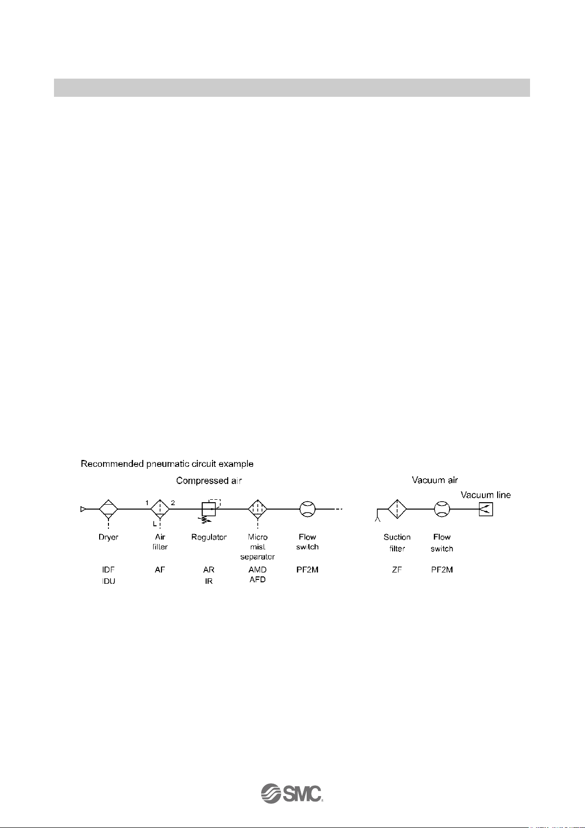
If there is a risk of foreign matter entering the fluid, install and pipe a filter or the mist separator at the
inlet to avoid failure and malfunction.
Otherwise damage or malfunction can result.
And it can cause inability to measure accurately.
Refer to the figure below for the recommended pneumatic circuit.
If the fluid flow on the IN side (entry side) of the product is unstable, correct measurement will not be
possible.
If a valve is used on the IN side (entry side) of the product, the fluid may be unstable due to the change of the
effective area, and there may be an error in the flow measurement results.

-7-
No.PF※※-OMW0007-A
Wiring
Do not pull the lead wires.
In particular, never lift a product equipped with fitting and piping by holding the lead wires.
Otherwise damage to the internal parts can result, causing malfunction or disconnection of the connector.
Avoid repeatedly bending or stretching the lead wire, or placing heavy loads on it
Repeated bending stress or tensile stress can cause damage to the sheath, or breakage of the wires.
If the lead wire can move, fix it near the body of the product.
The recommended bend radius of the lead wire is 6 times the outside diameter of the sheath, or 33 times the
outside diameter of the wire insulation material, whichever is larger.
Replace any damaged lead wire with a new one.
Wire correctly.
Incorrect wiring can damage the product.
Do not perform wiring while the power is on.
Otherwise damage to the internal parts can result, causing malfunction.
Do not route wires and cables together with power or high voltage cables.
Otherwise the product can malfunction due to interference or noise and surge voltage from power and high voltage
cables.
Confirm proper insulation of wiring.
Poor insulation (interference from another circuit, poor insulation between terminals, etc.) can lead to excess
voltage or current being applied to the product, causing damage.
Keep wiring as short as possible to prevent interference from electromagnetic noise and surge voltage.
Do not use a cable longer than 30 m.
Wire the DC (-) line (blue) as close as possible to the power supply.
When analogue output is used, install a noise filter (line noise filter, ferrite element, etc.) between the
switch-mode power supply and this product.

-8-
No.PF※※-OMW0007-A
Environment
Do not use the product in area that is exposed to corrosive gases, chemicals, sea water, water or steam.
Otherwise failure or malfunction can result.
Do not use in a place where the product could be splashed by oil or chemicals.
If the product is to be used in an environment containing oils or chemicals such as coolant or cleaning solvent, even
for a short time, it may be adversely affected (damage, malfunction, or hardening of the lead wires)
Do not use in an area where electrical surges are generated.
If there is equipment generates large electrical surges (solenoid type lifter, high frequency induction furnace, motor,
etc.) close to the product, damage or failure of the internal circuit may occur. Take measures against the surge
sources, and prevent the wires from coming into close contact.
Do not use a load which generates a surge voltage.
When a surge-generating load such as a relay or solenoid is driven directly, use a product with a built-in surge
absorbing element.
The product is CE marked, but not immune to lightning strikes. Take measures against lightning strikes
in the system.
Do not use the product in areas that are exposed to vibration or impact.
Otherwise failure or malfunction can result.
Do not use the product in the presence of a magnetic field.
This may lead to the malfunction of the product.
Prevent foreign matter such as wire debris from entering the product.
Otherwise failure or malfunction can result.
Do not use the product in areas subject to large temperature cycle.
Heating/cooling cycles other than ordinary changes in temperature can adversely affect the internal structure of the
product
Do not expose the product to direct sunlight.
If using in a location directly exposed to sunlight, use a suitable protective cover.
Otherwise failure or malfunction can result.
Keep within the operating fluid temperature and operation temperatures range.
The operating fluid temperature and operating temperature range is 0 to 50 oC.
Operation below the minimum temperature limit may cause damage or operation failure due to frozen moisture in
the fluid or air.
Protection against freezing is necessary.
An air dryer is recommended for elimination of drainage and water.
Avoid sudden temperature changes even within the specified temperature range.
Do not operate close to a heat source, or in a location exposed to radiant heat.
Otherwise malfunction can result.
The temperature between products rises when sticking is installed, and there is a possibility to influence
the performance of the product.

-9-
No.PF※※-OMW0007-A
Adjustment and Operation
Connect load before turning on the power.
Do not short-circuit the load.
Although an error is displayed when the product load is short circuited, excess current may cause damage to the
product.
Do not press the setting buttons with a sharp pointed object.
This may damage the setting buttons.
Supply the power when there is no flow.
The output is off for 3 seconds after power is supplied.
Use settings suitable for the operating conditions.
Incorrect settings can cause operational failure.
(Refer to page 23 " Flow setting".)
During the initial setting and any subsequent flow rate setting, the product will switch the output
according to the existing settings until the changes are complete.
Confirm the output has no adverse effect on machinery and equipment before setting.
Stop the control system before setting if necessary.
Do not touch the LCD during operation.
The display can vary due to static electricity.
Maintenance
Perform regular maintenance and inspections.
There is a risk of unexpected malfunction of components due to the malfunction of equipment and machinery.
Turn off the power supply, stop the supplied air, exhaust the residual pressure and verify the release of
air before performing maintenance.
There is a risk of unexpected malfunction.
Perform drainage regularly.
If condensate enters the outside, it can cause operating failure of pneumatic equipment.
Do not use solvents such as benzene, thinner etc. to clean the product.
They could damage the surface of the body and erase the markings on the body.
Use a soft cloth to remove stains.
For heavy stains, use a cloth lightly dampened with diluted neutral detergent, then wipe up any residue with a dry
cloth.
Other
If there is a restrictor fitted, vibration may cause the flow adjustment valve to rotate and change the flow
rate.
-10-
No.PF※※-OMW0007-A
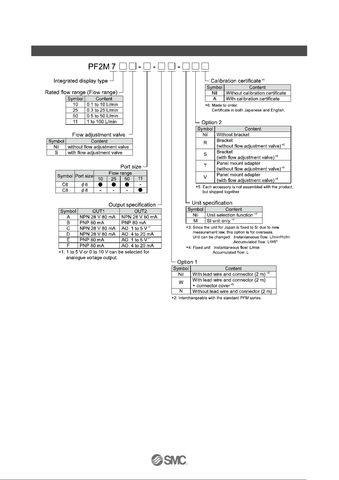
Model Indication and How to Order
-11-
No.PF※※-OMW0007-A
Option1
Nil W N
with lead wire and connector (2 m)
with lead wire and connector (2 m)
+
Connecter cover
(silicone rubber)
without lead wire
Option2
Nil R S
without bracket
with bracket
(without flow adjustment valve)
with bracket
(with flow adjustment valve)
T
V
with panel mount adapter
(without flow adjustment valve)
with panel mount adapter
(with flow adjustment valve)
: Each accessory is not assembled with the product, but shipped together.
-12-
No.PF※※-OMW0007-A
Accessories/Part number
If an accessory is required separately, order using the following part numbers.
Part number
Description
Remarks
ZS-33-D
Lead wire and connector
Length: 2 m
ZS-33-F
Connector cover (silicone rubber)
ZS-33-2J
Panel mount adapter (without flow adjustment valve)
ZS-33-2JS
Panel mount adapter (with flow adjustment valve)
ZS-33-M
Bracket (without flow adjustment valve)
Mounting screw 2 pcs.
ZS-33-MS
Bracket (with flow adjustment valve)
Mounting screw 3 pcs.
ZS-33-R#
DIN rail mounting parts
-13-
No.PF※※-OMW0007-A
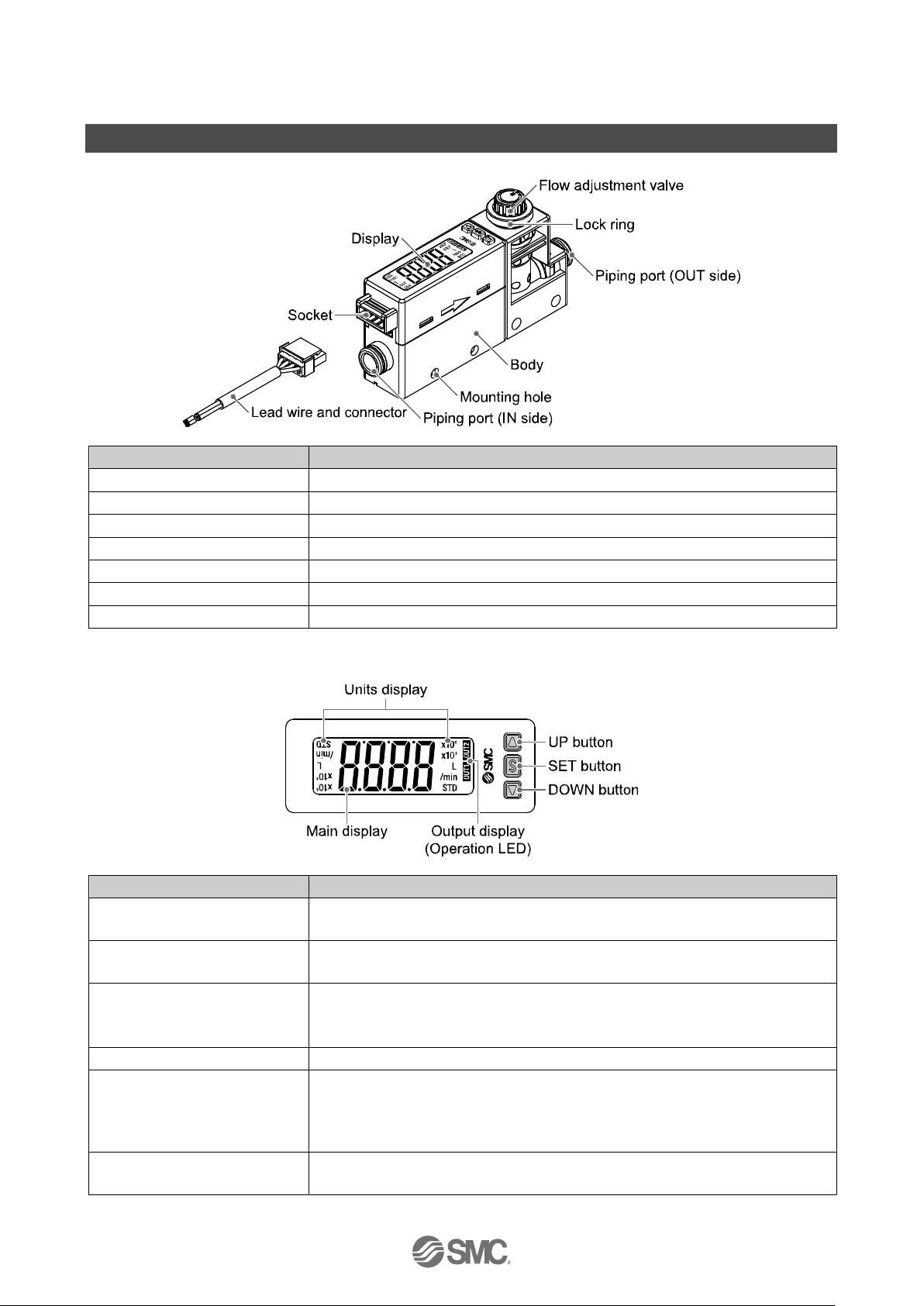
Summary of Product parts
Body
Item
Description
Socket
Socket for electrical connections.
Piping port
Connected to the fluid inlet at IN side and to the fluid outlet at OUT side.
Flow adjustment valve
Orifice mechanism to adjust the flow.
Lock ring
Used to lock the flow adjustment valve.
Mounting hole
Used to mount the product on a DIN rail or directly to a panel.
Body
The body of the product.
Lead wire and connector
Lead wire to supply power and transmit output signals.
: The table shows the specifications when a flow adjusting valve is included.
Display
Item
Description
UP
button
Selects the mode or increases the ON/OFF set value.
Press this button to change to the peak display mode.
DOWN button
Selects the mode or decreases the ON/OFF set value.
Press this button to change to the bottom display mode.
Main display
Displays the flow value, setting mode, and error indication.
Four display modes can be selected: display always in red or green, or display
changing from green to red, or red to green, according to the output status (OUT1).
SET button
Press this button to change to another mode and to set a value.
Output display (Operation LED)
Displays the output status of OUT1 and OUT2.
OUT1: LED is ON (Orange) when the output is ON.
OUT1: LED is ON (Orange) when the output is ON.
When the accumulated pulse output mode is selected, the output display is OFF.
Units display
Arbitrary units is ON based on the flow display setting (instantaneous or
accumulated flow)
: If the reversed display has been selected, the UP and DOWN button function will be reversed.
-14-
No.PF※※-OMW0007-A
■Definition and terminology
Terms
Meaning
A
Accumulated flow
The total amount of fluid that has passed through the device. If an instantaneous flow of
10 L/min continues for 5 minutes, the accumulated flow will be 10 × 5 = 50 L.
Accumulated pulse
output
A type of output where a pulse is generated every time a predefined accumulated flow
passes. It is possible to calculate the total accumulated flow by counting the pulses.
Accumulated-value
hold time
A function to store the cumulative flow value in the product's internal memory at certain
time intervals. Reads the memory data when power is supplied. Accumulation of data
begins with the value read at the moment power is supplied. The time interval for
memorizing can be selected from 2 or 5 minutes.
Analogue output
Outputs a value proportional to the flow rate. When the analogue output is in the range
1 to 5 V, it will vary between 1 to 5 V according to the rate of flow. The same for
analogue output of 0 to 10 V or 4 to 20 mA.
Auto-preset
This function will automatically calculate and set the optimum flow rate based on the
actual operating condition when hysteresis mode is selected.
C
Chattering
The problem of the switch output turning ON and OFF repeatedly around the set value
at high frequency due to the effect of pulsation.
D
Delay time
The setting time from when the flow applied to the flow switch reaches the set value, to
when the ON-OFF output actually begins working.
Delay time setting can prevent the output from chattering.
The response time indicates when the set value is 90% in relation to the step input.
digit (Min. setting unit)
Shows how precisely the flow can be displayed or set by the digital flow switch. When
1 digit = 1 L/min, the flow is displayed in increments of 1 L/min, e.g., 1, 2, 3, …, 99, 100.
Digital filter
Function to add digital filtering to the fluctuation of flow value. Smooth the fluctuation of
displayed value for sharp start up or fall of the flow.
When the function is valid, digital filtering is reflected to the ON/OFF of the switch
output.
Output chattering or flicker in the measurement mode display can be reduced by
setting the digital filter.
Display flow range
The range of measured values that can be displayed for a product with a digital display.
E
Error displayed
The code number displayed, identifying the error detected by the self-diagnosis
function of the pressure switch.
Refer to "Error indication" on page 65 for details of the errors.
Error output
Switches the switch output to ON/OFF when an error is displayed.
Refer to "List of output modes" on page 33 for operating conditions.
Refer to "Error indication" on page 65 for details of the errors.
F
F.S.
(Full span, Full scale)
Stands for "full span" or "full scale", and indicates varied display value and analogue
output range at rated value. For example, when analogue output is 1 to 5 V,
F.S. = 5[V] - 1[V] = 4[V], (ref. 1%F.S. = 4[V] x 1% = 0.04[V])
Fluid temperature
range
Range of fluid temperature that can be measured by the product.
-15-
No.PF※※-OMW0007-A
Terms
Meaning
H
Hysteresis
The difference between ON and OFF points used to prevent chattering. Hysteresis can
be effective in avoiding the effects of pulsation.
Hysteresis mode
Mode where the switch output will turn ON when the flow is greater than the set value,
and will turn off when the flow falls below (set value – hysteresis value).
I
Instantaneous flow
The flow passing per unit of time. If it is 10 L/min, there is a flow of 10 L passing through
the device in 1 minute.
Insulation resistance
Insulation resistance of the product. The resistance between the electrical circuit and
the case.
Internal voltage drop
The voltage drop across the product (and therefore not applied to the load), when the
switch output is ON. The voltage drop will vary with load current, and ideally should be
0 V.
K
Key-lock function
This function prevents the set value from being changed by mishandling.
M
Maximum applied
voltage
The maximum voltage that can be connected to the output of an NPN device.
Maximum load current
The maximum current that can flow to the output (output line) of the switch output.
Max. (Min.) load
impedance
The maximum (minimum) load (resistance value and impedance) which can be
connected to the output (output wire)of the analogue current output.
Measurement mode
Operating condition in which flow is being detected and displayed, and the switch
function is working.
Min. setting unit
Shows how precisely the flow can be displayed or set by the digital flow switch. When
1 digit = 1 L/min, the flow is displayed in increments of 1 L/min, e.g., 1, 2, 3, …, 99, 100.
O
Operating humidity
range
Humidity range in which the product can operate.
Operating temp. range
Ambient temperature range in which product is operable.
Output impedance
The resistance value of a component between the voltage output element and the
analogue voltage output. It is indicated as a resistance value which is converted in
accordance with the condition in which resistance is directly connected to the voltage
output element. There may be an error in the output voltage depending on this output
impedance and the input impedance of customers' equipment. (example: If the flow
switch with output impedance of 1 kΩ is connected to the A/D converter to detect the
analogue output of 5 V, the detected voltage by the A/D converter becomes 5(V)
x1(MΩ)/(1(kΩ) + 1(MΩ)) ≒4.995(V), and there is an error of approximate 0.005 V).
-16-
No.PF※※-OMW0007-A
Terms
Meaning
P
Part in contact with
fluid
A part that comes into physical contact with the fluid.
Pressure
characteristics
Indicates the change in the display value and analogue output when fluid pressure
changes.
Proof pressure
Burst pressure at which the product is electrically or mechanically damaged.
R
Rated flow range
The flow range within which the product will meet all published specifications.
Rated pressure range
The pressure range that satisfies the specifications.
Repeatability
Reproducibility of the display or analogue output value, when the measured quantity is
repeatedly increased and decreased.
Ripple
Indicates pulsation.
S
Set flow range
The range of ON/OFF threshold values that can be set for those products with a switch
output.
Switch output
Output type that has only 2 conditions, ON or OFF. When in the ON condition an
indicator light will show, and any connected load will be powered. When in the OFF
condition, there will be no indicator light and no power supplied to the load.
T
Temperature
characteristics
Indicates the change in the display value and analogue output caused by ambient
temperature changes.
U
Unit selection function
A function to select display units other than the international unit (SI unit) specified in
the new Japanese measurement law. Flow can only be displayed by SI units in Japan.
W
Window comparator
mode
An operating mode in which the switch output is turned on and off depending on
whether the flow is inside or outside the range of two set values.
Withstand voltage
A measure of the product’s resistance to a voltage applied between the electrical circuit
and case. Durability in withstanding voltage. The product may be damaged if a voltage
over this value is applied.
(The withstand voltage is not the supply voltage used to power the product.)
Z
Zero-clear function
This function to adjust the displayed flow to zero.
-17-
No.PF※※-OMW0007-A
Mounting and Installation
■Installation
Refer to the flow direction of the fluid indication on the product label for installation and piping.
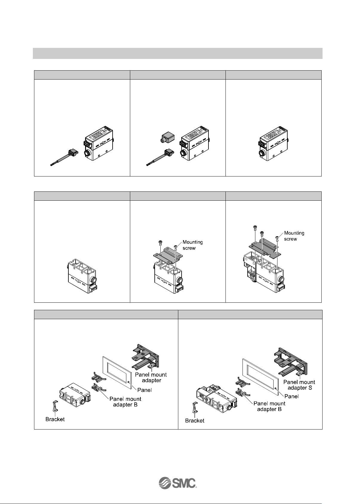
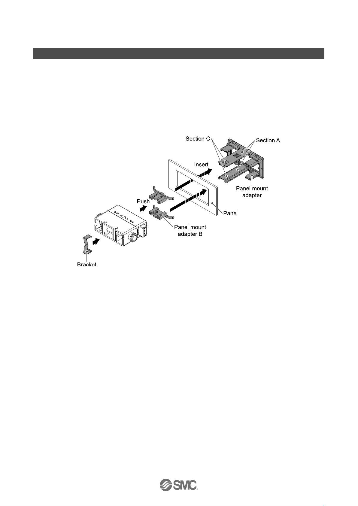
Panel mounting
Insert panel mount adapter B (supplied as an accessory) into section A of panel mount adapter.
Push panel mount adapter B from behind until the display is fixed onto the panel.
The pin of bracket engages the notched part of panel adapter section C to fix the display.
The switch can be mounted on a panel with a thickness of 1 to 3.2 mm.
Refer to the dimension drawing (page 73) for panel cut-out dimensions.

-18-
No.PF※※-OMW0007-A
Bracket mounting
Mount the bracket using the mounting screws supplied.
The required tightening torque is 0.42±0.04 Nm.
Without flow adjustment valve
(using ZS-33-M)
With flow adjustment valve
(using ZS-33-MS)
Install the product (with bracket) using the M3 screws (4 pcs.).
Bracket thickness is approximately 1.2 mm.
Refer to the dimension drawing of the bracket (page 73) for mounting hole dimensions.
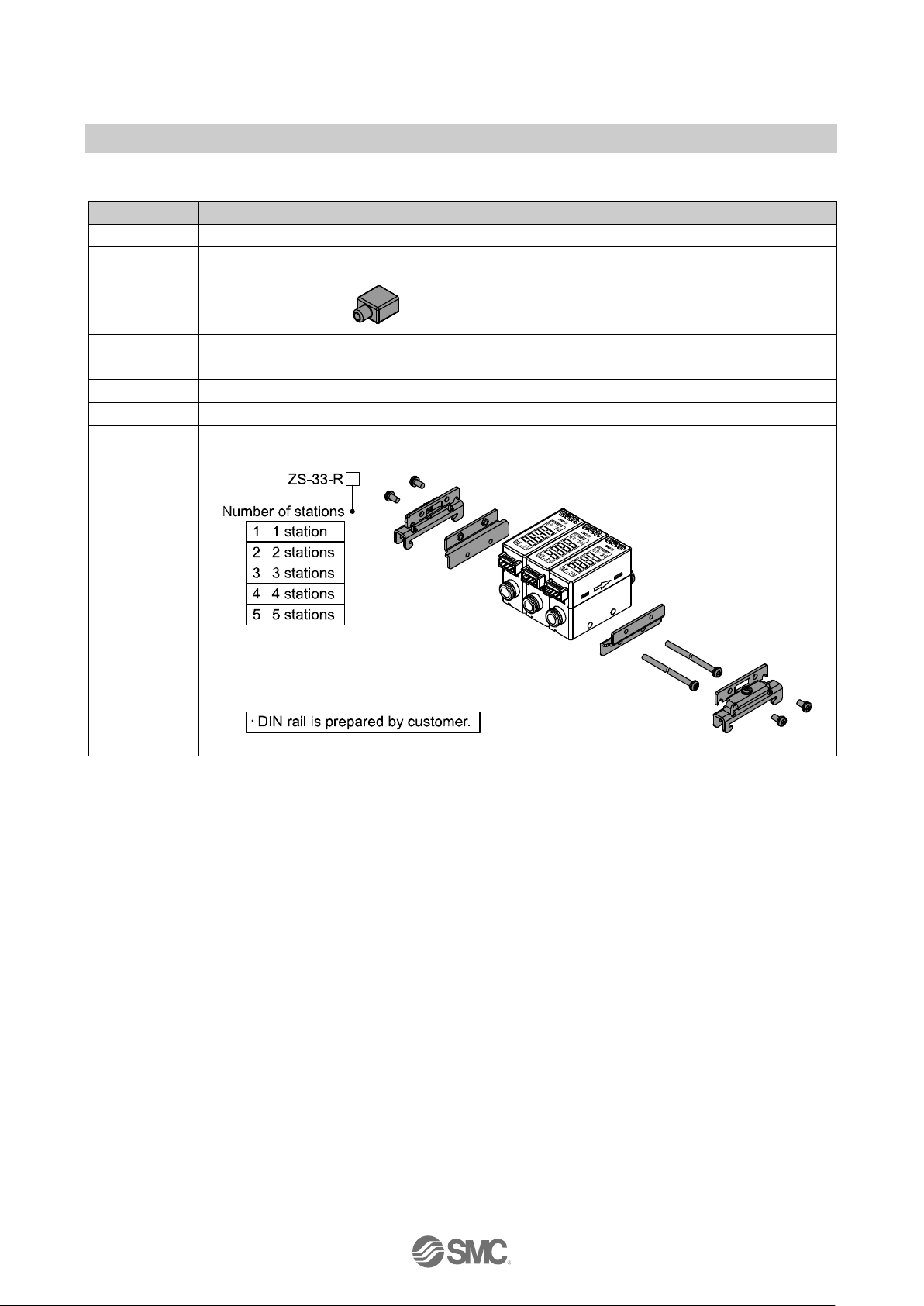
DIN rail mounting (using ZS-33-R#)
Mount the DIN rail mounting parts using DIN rail mounting screws and joint screws supplied.
The required tightening torque of the DIN rail mounting screws and joint screws is 0.4±0.05 Nm.
-19-
No.PF※※-OMW0007-A
■Wiring
Wiring of connector
Connections should only be made with the power supply turned off.
Use separate routes for the product wiring and any power or high voltage wiring. Otherwise, malfunction
may result due to noise.
Ensure that the FG terminal is connected to ground when using a commercially available switch-mode
power supply. When a switch-mode power supply is connected to the product, switching noise will be
superimposed and the product specification can no longer be met. This can be prevented by inserting a
noise filter, such as a line noise filter and ferrite core, between the switch-mode power supply and the
product, or by using a series power supply instead of a switch-mode power supply.
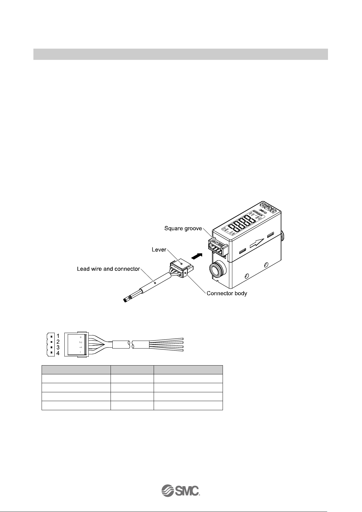
Connecting/Disconnecting
When mounting the connector, insert it straight into the socket, holding the lever and connector body, and
push the connector until the lever hooks into the housing, and locks.
When removing the connector, press down the lever to release the hook from the housing and pull the
connector straight out.
Connector pin numbers (on the lead wire)
Connector pin numbers
Wire colour
Description
1
Brown
DC(+) 2 White
OUT2/Analogue output
3
Black
OUT1 4 Blue
DC(-)
-20-
No.PF※※-OMW0007-A
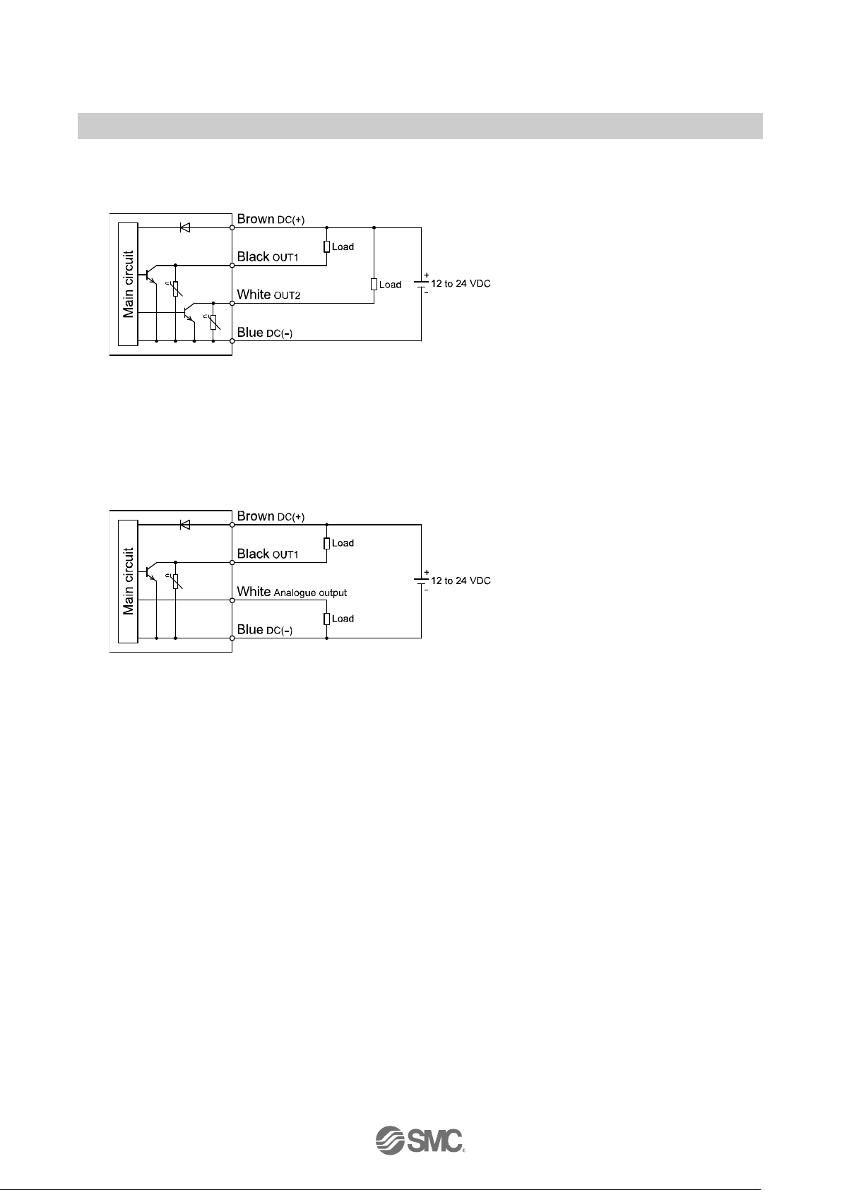
Internal circuit and wiring example
NPN (2 outputs) type
PF2M7##-#-A#-###
Max. 28 V, 80 mA
Internal voltage drop: 1 V or less
NPN (1 output) + Analogue (1 to 5 V/0 to 10 V) output type
PF2M7##-#-C#-###
NPN (1 output) + Analogue (4 to 20 mA) output type
PF2M7##-#-D#-###
Max. 28 V, 80 mA
Internal voltage drop: 1 V or less
C: Analogue output: 1 to 5 V/0 to 10 V
Output impedance: 1 kΩ
D: Analogue output: 4 to 20 mA
Max. load impedance: 600 Ω
Min. load impedance: 50 Ω
-21-
No.PF※※-OMW0007-A
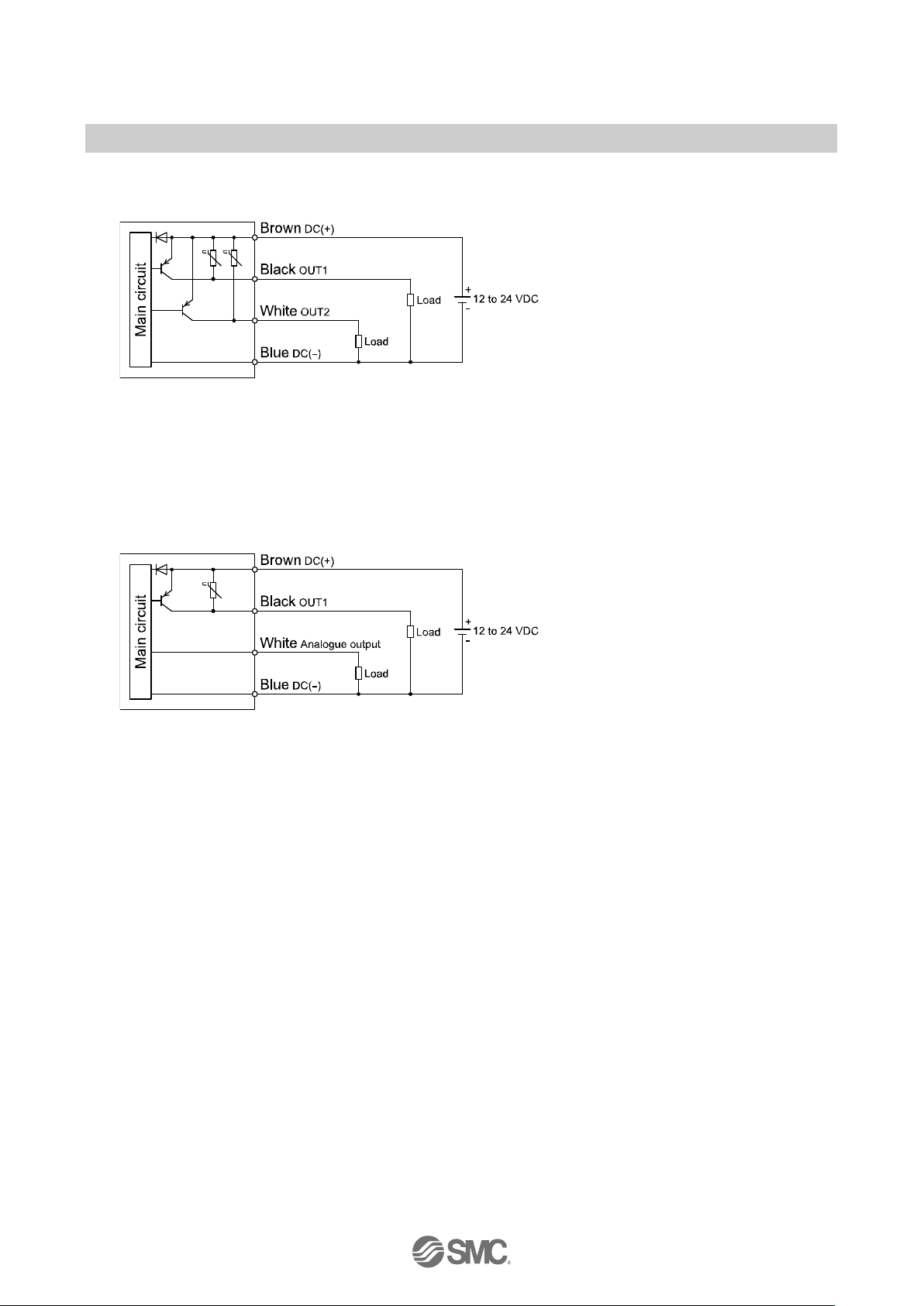
PNP (2 outputs) type
PF2M7##-#-B#-###
Max. 80 mA
Internal voltage drop: 1.5 V or less
PNP (1 output) + Analogue (1 to 5 V/0 to 10 V) output type
PF2M7##-#-E#-###
PNP (1 output) + Analogue (4 to 20 mA) output type
PF2M7##-#-F#-###
Max. 80mA
Internal voltage drop: 1.5 V or less
E: Analogue output: 1 to 5 V/0 to 10 V
Output impedance: 1 kΩ
F: Analogue output: 4 to 20 mA
Max. load impedance: 600 Ω
Min. load impedance: 50 Ω
-22-
No.PF※※-OMW0007-A
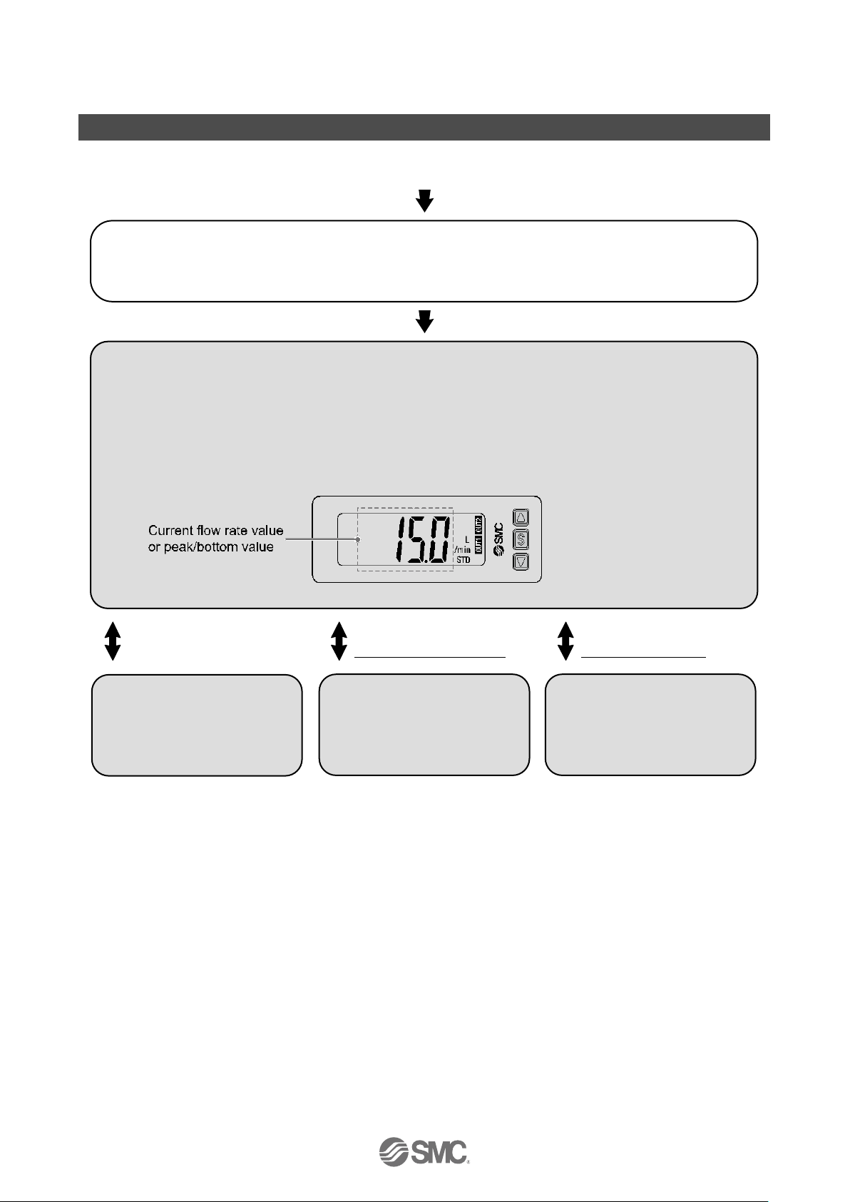
Outline of Settings
Power is supplied.
The product code is displayed for approximately 3 sec. after power is supplied.
Then, measurement mode will be displayed.
: After moving on to the measurement mode, the switch operation will start.
[Measurement mode]
Measurement mode is the condition where the flow is detected and displayed, and the
switch function is operating.
This is the basic mode; other modes should be selected for set-point changes and other
function settings.
Measurement mode screen
Press the SET button
once.
Press the SET button
between 2 to 5 seconds.
Press the SET button for
5 seconds or longer.
Change of Set Flow and
Hysteresis
(Simple setting mode)
(Refer to page 24)
Change the Function
Settings
(Function selection mode)
(Refer to page 25)
Other Settings
•Key-lock
(Refer to page 57)
: The outputs will continue to operate during setting.
: Simple setting mode and function selection mode settings are reflected each other.
-23-
No.PF※※-OMW0007-A
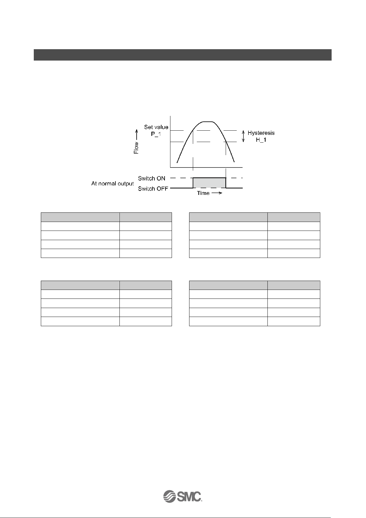
Flow Setting
Switch operation
When the flow exceeds the set value, the switch will turn ON.
When the flow falls below the set value by the amount of hysteresis or more, the switch will turn OFF.
The default setting is to turn on the flow switch when the flow reaches the center of the upper limit of the rated
flow range.
If this condition, shown to the below, is acceptable, then keep these settings.
●PF2M710
Item
Default Settings
[P_1] Set value of OUT1
5.00 L/min
[H_1] Hysteresis of OUT1
0.50 L/min
[P_2] Set value of OUT2
5.00 L/min
[H_2] Hysteresis of OUT2
0.50 L/min
●PF2M725
Item
Default Settings
[P_1] Set value of OUT1
12.5 L/min
[H_1] Hysteresis of OUT1
1.3 L/min
[P_2] Set value of OUT2
12.5 L/min
[H_2] Hysteresis of OUT2
1.3 L/min
●PF2M750
Item
Default Settings
[P_1] Set value of OUT1
25.0 L/min
[H_1] Hysteresis of OUT1
2.5 L/min
[P_2] Set value of OUT2
25.0 L/min
[H_2] Hysteresis of OUT2
2.5 L/min
●PF2M711
Item
Default Settings
[P_1] Set value of OUT1
50.0 L/min
[H_1] Hysteresis of OUT1
5.0 L/min
[P_2] Set value of OUT2
50.0 L/min
[H_2] Hysteresis of OUT2
5.0 L/min
: Only available for models with switch outputs for both OUT1 and OUT2
: For hysteresis, please refer to [F 1] Setting of OUT1 (page 29), [F 2] Setting of OUT2 (page 34).
 Loading...