

Page 1
No.PF※※-OMG0006-F
PRODUCT NAME
Digital Flow Switch
(Remote type sensor unit)
MODEL / Series / Product Number
PF2D5##
Page 2

-1-
No.PF※※-OMG0006-F
Table of Contents
Safety Instructions 2
Model Indication and How to Order 10
Summary of Product parts 11
Definition and terminology 12
Mounting and Installation 13
Installation 13
Piping 14
Wiring 15
Troubleshooting 17
Cross-reference for troubleshooting 17
Specification 18
Specifications 18
Material of parts in contact with fluid and fluids compatibility checklist 19
Characteristics data 20
Dimensions 22
Made to Order 24
Page 3
-2-
No.PF※※-OMG0006-F
Safety Instructions
These safety instructions are intended to prevent hazardous situations and/or equipment damage.
These instructions indicate the level of potential hazard with the labels of "Caution", "Warning" or "Danger".
They are all important notes for safety and must be followed in addition to International Standards
(ISO/IEC)*1), and other safety regulations.
*1) ISO 4414: Pneumatic fluid power -- General rules relating to systems.
ISO 4413: Hydraulic fluid power -- General rules relating to systems.
IEC 60204-1: Safety of machinery -- Electrical equipment of machines. (Part 1: General requirements)
ISO 10218: Manipulating industrial robots -Safety.
etc.
Caution
Caution indicates a hazard with a low level of risk which, if not avoided, could
result in minor or moderate injury.
Warning
Warning indicates a hazard with a medium level of risk which, if not avoided,
could result in death or serious injury.
Danger
Danger indicates a hazard with a high level of risk which, if not avoided, will
result in death or serious injury.
Warning
1. The compatibility of the product is the responsibility of the person who designs the
equipment or decides its specifications.
Since the product specified here is used under various operating conditions, its compatibility with specific
equipment must be decided by the person who designs the equipment or decides its specifications
based on necessary analysis and test results.
The expected performance and safety assurance of the equipment will be the responsibility of the
person who has determined its compatibility with the product.
This person should also continuously review all specifications of the product referring to its latest catalog
information, with a view to giving due consideration to any possibility of equipment failure when
configuring the equipment.
2. Only personnel with appropriate training should operate machinery and equipment.
The product specified here may become unsafe if handled incorrectly.
The assembly, operation and maintenance of machines or equipment including our products must be
performed by an operator who is appropriately trained and experienced.
3. Do not service or attempt to remove product and machinery/equipment until safety is
confirmed.
1. The inspection and maintenance of machinery/equipment should only be performed after measures to
prevent falling or runaway of the driven objects have been confirmed.
2. When the product is to be removed, confirm that the safety measures as mentioned above are
implemented and the power from any appropriate source is cut, and read and understand the specific
product precautions of all relevant products carefully.
3. Before machinery/equipment is restarted, take measures to prevent unexpected operation and malfunction.
4. Contact SMC beforehand and take special consideration of safety measures if the
product is to be used in any of the following conditions.
1. Conditions and environments outside of the given specifications, or use outdoors or in a place
exposed to direct sunlight.
2. Installation on equipment in conjunction with atomic energy, railways, air navigation, space, shipping,
vehicles, military, medical treatment, combustion and recreation, or equipment in contact with food and
beverages, emergency stop circuits, clutch and brake circuits in press applications, safety equipment or
other applications unsuitable for the standard specifications described in the product catalog.
3. An application which could have negative effects on people, property, or animals requiring special
safety analysis.
4. Use in an interlock circuit, which requires the provision of double interlock for possible failure by using
a mechanical protective function, and periodical checks to confirm proper operation.
Page 4
-3-
No.PF※※-OMG0006-F
Safety Instructions
Caution
1.The product is provided for use in manufacturing industries.
The product herein described is basically provided for peaceful use in manufacturing industries.
If considering using the product in other industries, consult SMC beforehand and exchange
specifications or a contract if necessary.
If anything is unclear, contact your nearest sales branch.
Limited warranty and Disclaimer/Compliance Requirements
The product used is subject to the following "Limited warranty and Disclaimer" and "Compliance
Requirements".
Read and accept them before using the product.
Limited warranty and Disclaimer
1. The warranty period of the product is 1 year in service or 1.5 years after the product is
delivered, whichever is first.2)
Also, the product may have specified durability, running distance or replacement parts.
Please consult your nearest sales branch.
2. For any failure or damage reported within the warranty period which is clearly our
responsibility, a replacement product or necessary parts will be provided.
This limited warranty applies only to our product independently, and not to any other
damage incurred due to the failure of the product.
3. Prior to using SMC products, please read and understand the warranty terms and
disclaimers noted in the specified catalog for the particular products.
2) Vacuum pads are excluded from this 1 year warranty.
A vacuum pad is a consumable part, so it is warranted for a year after it is delivered.
Also, even within the warranty period, the wear of a product due to the use of the
vacuum pad or failure due to the deterioration of rubber material are not covered by the
limited warranty.
Compliance Requirements
1. The use of SMC products with production equipment for the manufacture of weapons of
mass destruction (WMD) or any other weapon is strictly prohibited.
2. The exports of SMC products or technology from one country to another are governed by
the relevant security laws and regulation of the countries involved in the transaction. Prior
to the shipment of a SMC product to another country, assure that all local rules governing
that export are known and followed.
Caution
SMC products are not intended for use as instruments for legal metrology.
Products that SMC manufactures or sells are not measurement instruments that are qualified by pattern
approval tests relating to the measurement laws of each country.
Therefore, SMC products cannot be used for business or certification ordained by the measurement laws of
each country.
Page 5
-4-
No.PF※※-OMG0006-F
Operator
This operation manual is intended for those who have knowledge of machinery using pneumatic
equipment, and have sufficient knowledge of assembly, operation and maintenance of such
equipment. Only those persons are allowed to perform assembly, operation and maintenance.
Read and understand this operation manual carefully before assembling, operating or providing
maintenance to the product.
■Safety Instructions
Warning
■Do not disassemble, modify (including changing the printed circuit board) or repair.
An injury or failure can result.
■Do not operate the product outside of the specifications.
Do not use for flammable or harmful fluids.
Fire, malfunction, or damage to the product can result.
Verify the specifications before use.
■Do not operate in an atmosphere containing flammable, explosive or corrosive gas.
Fire, explosion or corrosion can result.
This product is not designed to be explosion proof.
■Do not use the product for flammable or highly permeable fluids.
Fire, explosion, corrosion or damage can result.
Refer to the Material Safety Data Sheet and confirm safety before use.
■Do not use the product in a place where static electricity is a problem.
Otherwise it can cause failure or malfunction of the system.
■If using the product in an interlocking circuit:
Provide a double interlocking system, for example a mechanical system
Check the product regularly for proper operation
Otherwise malfunction can result, causing an accident.
■The following instructions must be followed during maintenance:
Turn off the power supply
Ensure the flow is shut off before performing maintenance
Otherwise an injury can result.
Page 6
-5-
No.PF※※-OMG0006-F
Caution
■Do not touch the terminals and connectors while the power is on.
Otherwise electric shock, malfunction or damage to the product can result.
■Do not touch the piping or its connected parts when the fluid is at high temperature.
It may lead to burnt.
Ensure the piping cools sufficiently before touching.
■After maintenance is complete, perform appropriate functional inspections and leak tests.
Stop operation if the equipment does not function properly or there is a leakage of fluid.
When leakage occurs from parts other than the piping, the product might be faulty.
Disconnect the power supply and stop the fluid supply.
Do not apply fluid under leaking conditions.
Safety cannot be assured in the case of unexpected malfunction.
■NOTE
○Follow the instructions given below when designing, selecting and handling the product.
●The instructions on design and selection (installation, wiring, environment, adjustment, operation,
maintenance, etc.) described below must also be followed.
Product specifications
Use the specified voltage.
Otherwise failure or malfunction can result.
Insufficient supply voltage may not drive a load due to a voltage drop inside the product.
Verify the operating voltage of the load before use.
Do not exceed the specified maximum allowable load.
Otherwise it can cause damage or shorten the lifetime of the product.
Applicable fluids are DI water and fluids which do not corrode or erode fluoropolymer.
Fluid viscosity should be 3 mPa●s (3 cP) or less.
The operating fluid temperature range is 0 to 90 oC.
Confirm the pressure loss at the sensor according to the pressure loss graph before designing piping.
Confirm detection condition of sensor electrified potential.
Consider measures to prevent over pressure due to water hammer.
<Measures to reduce water hammer>
1. Install a water hammer relieving valve.
2. Use a flexible material for piping (such as a rubber hose) and an accumulator that can absorb impact pressure.
3. Keep piping as short as possible.
Use within the specified measurement flow rate, operating pressure and temperature range.
Otherwise it can cause damage to the product or inability to measure correctly.
Rated pressure range and proof pressure depend on the fluid temperature. Refer to the specifications.
Reserve a space for maintenance.
Allow sufficient space for maintenance when designing the system.
Page 7

-6-
No.PF※※-OMG0006-F
●Product handling
Installation
Avoid displacement of the product and loose screws.
Tightening with excessive force may damage the product.
Ensure that the FG terminal is connected to ground when using a commercially available switch-mode
power supply.
Do not drop, hit or apply excessive shock to the product.
Otherwise damage to the internal parts can result, causing malfunction.
Do not pull the lead wire forcefully, or lift the product by the lead wire. (Tensile force 49 N or less)
Hold the product body when handling, to prevent damage, failure or malfunction.
The tensile strength of the power supply/output connection cable is 50 N and the sensor lead wire with a
connector is 25 N.
Any dust left in the piping should be flushed out by air blow before connecting the piping to the product.
Otherwise damage or malfunction can result.
Refer to the flow direction of the fluid indicated on the product label for installation and piping.
Do not mount the body with the bottom facing upwards.
Avoid piping in which the piping size of the IN side of the product changes suddenly.
If the piping size is reduced sharply or there is a restrictor such as a valve on the IN side, fluid velocity distribution
in the piping will be disturbed, leading to improper measurement.
Therefore, the above-mentioned piping should be connected on the OUT side.
If the OUT side is opened, or flow rate is excessive, cavitations may be generated, which may result in improper
measurement.
As a measure against this, it is possible to reduce the cavitations by increasing the fluid pressure.
Take action such as mounting an orifice on the OUT side of the product, and confirm that there is no malfunction
before handling.
If the orifice of the OUT side is fully closed to operate the pump, the switch may malfunction due to the effect of
pulsation (pressure fluctuation). Ensure that there is no malfunction before usage.
Do not insert metal wires or other foreign matter into the piping port.
This can damage the sensor causing failure or malfunction.
Never mount a product in a location that will be used as a foothold.
The product may be damaged if excessive force is applied by stepping or climbing onto it.
If the fluid may contain foreign matter, install and connect a filter to the inlet.
The adherence of foreign matter to the vortex generator or detector can cause errors in measurement accuracy.
Design and install the application so that the fluid detection path is always full.
If the product is mounted vertically, let the liquid flow from bottom to top.
Trapped air bubbles can cause errors in measurement accuracy.
(If the fluid detection path is always filled with liquid, there will be no problem.)
If the PF2D5 and LQ fluoropolymer fittings series are ordered separately, it is not possible to assemble
them with the tubing insertion tool of the LQ series. Please send them back to SMC. After assembling it,
it will be delivered to you.
Page 8

-7-
No.PF※※-OMG0006-F
Wiring
Do not pull the lead wires.
In particular, never lift a product equipped with fitting and piping by holding the lead wires.
Otherwise damage to the internal parts can result, causing malfunction.
Avoid repeatedly bending or stretching the lead wire, or placing heavy loads on it.
Repeated bending stress or tensile stress can cause damage to the sheath, or breakage of the wires.
If the lead wire can move, fix it near the body of the product.
The recommended bend radius of the lead wire is 6 times the outside diameter of the sheath, or 33 times the
outside diameter of the wire insulation material, whichever is larger.
Wire correctly.
Incorrect wiring can damage the product.
Do not perform wiring while the power is on.
Otherwise damage to the internal parts can result, causing malfunction.
Do not route wires and cables together with power or high voltage cables.
Otherwise the product can malfunction due to interference or noise and surge voltage from power and high voltage
cables to the signal line. Route the wires (piping) of the product separately from power or high voltage cables.
Confirm proper insulation of wiring.
Poor insulation (interference from another circuit, poor insulation between terminals, etc.) can lead to excess
voltage or current being applied to the product, causing damage.
Keep wiring as short as possible to prevent interference from electromagnetic noise and surge voltage.
Do not use a cable longer than 30 m.
Wire the DC(-) line (blue) as close as possible to the power supply.
When analogue output is used, install a noise filter (line noise filter, ferrite element, etc.) between the
switch-mode power supply and this product.
Page 9

-8-
No.PF※※-OMG0006-F
Environment
Do not use the product in an environment that is constantly exposed to the splash of water.
Otherwise failure or malfunction can result. Take measures such as using a cover.
Do not use the product in an environment where corrosive gases or fluids could be splashed.
Otherwise damage to the product and malfunction can result.
Do not use in a place where the product could be splashed by oil or chemicals.
If the product is to be used in an environment containing oils or chemicals such as coolant or cleaning solvent,
even for a short time, it may be adversely affected (damage, malfunction, or hardening of the lead wires)
Do not use in an area where electrical surges are generated.
If there is equipment generates large electrical surges (solenoid type lifter, high frequency induction furnace, motor,
etc.) close to the product, damage or failure of the internal circuit may occur. Take measures against the surge
sources, and prevent the wires from coming into close contact.
Do not use a load which generates a surge voltage.
When a surge-generating load such as a relay or solenoid is driven directly, use a product with a built-in surge
absorbing element.
The product is CE marked, but not immune to lightning strikes. Take measures against lightning strikes
in the system.
Do not use the product in areas that are exposed to vibration or impact.
Otherwise failure or malfunction can result.
Do not use the product in the presence of a magnetic field.
This may lead to the malfunction of the product.
Prevent foreign matter such as wire debris from entering the product.
Otherwise failure or malfunction can result.
Do not use the product in areas subject to large temperature cycle.
Heating/cooling cycles other than ordinary changes in temperature can adversely affect the internal structure of the
product.
Do not expose the product to direct sunlight.
If using in a location directly exposed to sunlight, use a suitable protective cover.
Otherwise failure or malfunction can result.
Keep within the operating fluid temperature and operating temperatures range.
The operating fluid temperature is 0 to 90 oC and operating temperature range is 0 to 50 oC.
If the fluid freezes, it may cause damage and malfunction of the switch, so please take measures to prevent
freezing.
When a fluid at a lower temperature than the ambient temperature is supplied, the product can break due to
condensation and malfunction. Keep the product from having condensation.
Please be aware that water droplets may cause early deterioration/damage, particularly if the product is installed
vertically or upside-down.
Protection against freezing is necessary.
Avoid sudden temperature changes even within the specified temperature range
Do not operate close to a heat source, or in a location exposed to radiant heat.
Otherwise malfunction can result.
Page 10

-9-
No.PF※※-OMG0006-F
Adjustment and Operation
Connect load before turning on the power.
Supply the power when there is no flow.
If using the product to detect very small flow rates, warm up the product for 10 to 15 minutes first. There
will be a drift on the analogue output of approximate 2 to 3% immediately after the power supply is turn
on, within 10 minutes.
Check regulators and flow adjustment valves before introducing the fluid.
If pressure or flow rate beyond the specified range are applied to the sensor, the sensor unit may be damaged.
Do not attempt to insert or pull the flow rate sensor or its connector when the power is on.
The product is a flow meter using Karman vortex. The flow meter using Karman vortex has lower output
frequency at excess flow state. Do not use the product within the excess flow area in the chart below.
Maintenance
Perform regular maintenance and inspections.
There is a risk of unexpected malfunction of components due to the malfunction of equipment and machinery.
Turn off the power supply, stop the fluid and check the safety before performing any maintenance.
There is a risk of unexpected malfunction.
Do not touch any chemicals left in the piping and the products.
Check the characteristics of chemicals used, and handle them appropriately.
Do not use solvents such as benzene, thinner etc. to clean the product.
They could damage the surface of the body and erase the markings on the body.
Use a soft cloth to remove stains.
For heavy stains, use a cloth lightly dampened with diluted neutral detergent, then wipe up any residue with a dry
cloth.
Check the name and the nature of chemicals used and treat them accordingly.
Page 11

-10-
No.PF※※-OMG0006-F
Model indication and How to Order
Accessories/Part number
If an accessory is required separately, order using the following part numbers.
Part number
Description
Qty.
Weight
ZS-28-CA-2
Connector
1 pc.
2 g
Page 12
-11-
No.PF※※-OMG0006-F
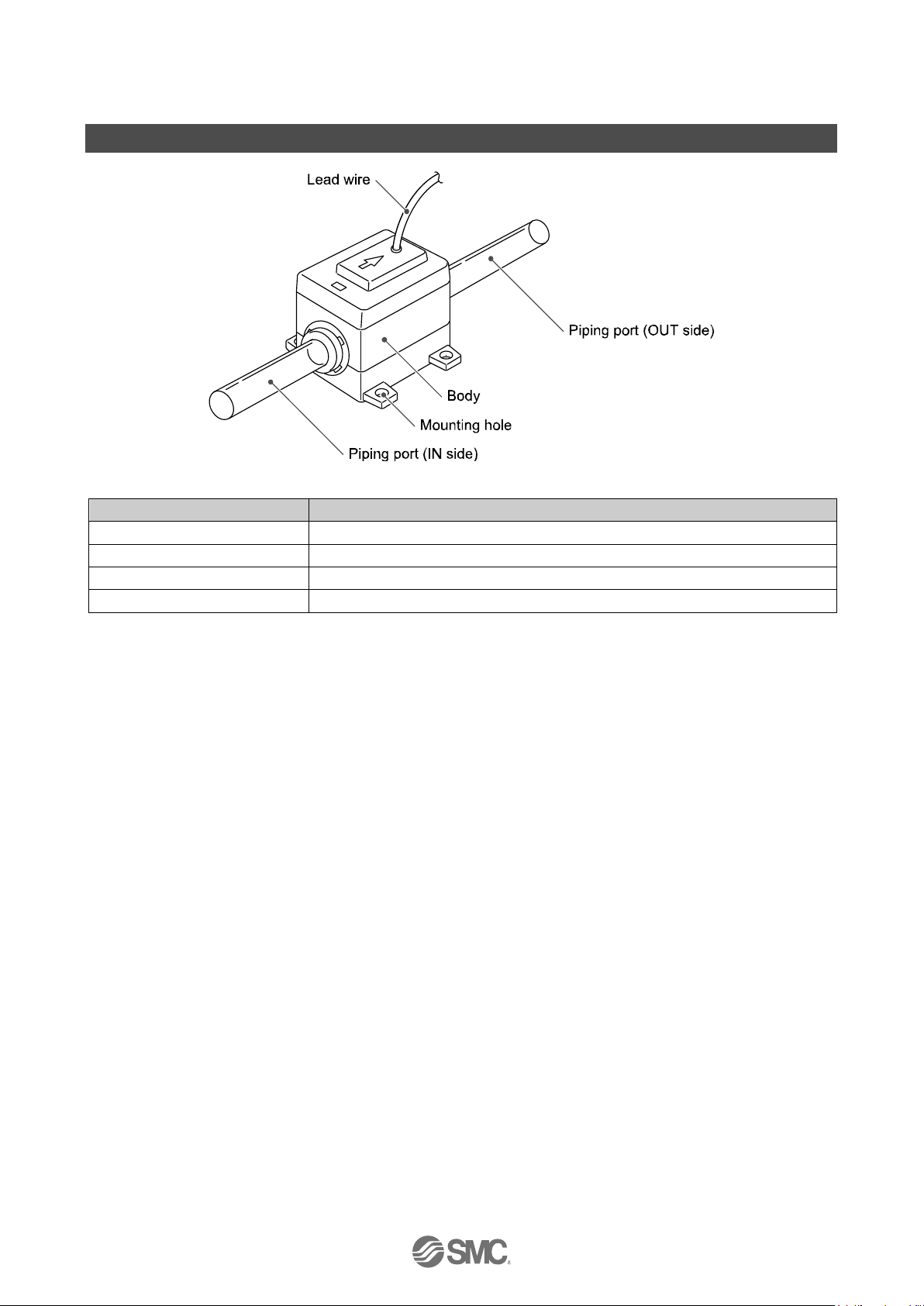
Summary of Product parts
Item
Description
Body
The body of the product.
Piping port (Tube)
Connected to the fluid inlet at IN side and to the fluid outlet at OUT side.
Mounting hole
Used to mount the product.
Lead wire
Lead wire to supply power and transmit output signals. (3 m)
Page 13

-12-
No.PF※※-OMG0006-F
■Definition and terminology
Terms
Meaning
A
Analogue output
A type of variable output that has a value proportional to the measured quantity. When
the analogue output is in the range of 1 to 5 V or 4 to 20 mA, it will vary continuously,
following the change of flow
C
Cavitation
A phenomenon that may occur in a fluid moving at high speed. In the parts of the fluid
where the pressure is low, vapour bubbles form and then rapidly collapse. If cavitation
is present for a prolonged period, exposed surfaces will be damaged; this is called
cavitation damage or erosion.
F
Fluid temperature
Range of fluid temperature that can be measured by the product.
F.S.
(Full span, Full scale)
Stands for "full span" or "full scale", and indicates varied analogue output range at rated
value. For example, when analogue output is 1 to 5 V, F.S. = 5[V] - 1[V] = 4[V], (ref.
1%F.S. = 4[V]x1% = 0.04[V])
The maximum measuring range or change in analogue output over the maximum
measurement range.
K
Karman vortex
When an object is placed in a fluid stream, a vortex will be created in the fluid on the
downstream side. This vortex is called a Karman vortex. The frequency at which the
vortices are generated is proportional to the fluid velocity, therefore it is possible to
calculate the fluid flow rate by measuring the Karman vortex frequency.
O
Operating humidity
range
The ambient humidity range within which the product will meet all published
specifications.
Operating
temperature range
The ambient temperature range within which the product will meet all published
specifications.
P
Part in contact with
fluid
A part that comes into physical contact with the fluid.
Pressure
characteristics
The amount of variation in the analogue output or display value when the supply
pressure is changed.
Proof pressure
The pressure beyond which the flow switch will be damaged.
R
Rated flow range
The flow range within which the product will meet all published specifications.
Rated pressure range
The pressure range within which the product will meet all published specifications.
Repeatability
Reproducibility of the display or analogue output value, when the flow is repeatedly
changing.
Response time
Time from when the target flow is applied until the flow reaches 90% of the set value.
T
Temperature
characteristics
The amount of variation in the analogue output or display value when the ambient
temperature is changed.
W
Water hammer
A momentary steep pressure increase due the spread of pressure by closing a
contactor such as a valve for an extremely short time while there is a flow.
This pressure increase is known as water hammer or impact pressure.
Page 14

-13-
No.PF※※-OMG0006-F
Mounting and Installation
■Installation
Never mount the product in a location that will be used as a foothold.
●Installing
Install the product (with bracket) using the M4 screws (4 pcs.).
The required tightening torque is 0.69 to 0.83 Nm.
Tightening with excessive force may damage the product.
Refer to the dimension drawing (page 22) for mounting hole dimensions.
Page 15

-14-
No.PF※※-OMG0006-F
■Piping
Use the product within the specified operating pressure range and temperature range.
Proof pressure is 1.5 MPa for PF2D504/520 and 0.9 MPa for PF2D540. Proof pressure could vary according
to the fluid temperature. Check the characteristics data for operating pressure and proof pressure (page 21).
Connect the piping using suitable fittings.
Mount the product so that the fluid direction is the same as the arrow indicated on the product.
The piping on the IN side must have a straight section of piping whose length is 8 times the piping
diameter or more.
Avoid sudden changes in the piping size on the IN side of the product.
Bubbles may be generated depending on the piping design. Refer to an example of recommended piping
system.
●Connecting the piping
LQ1 fitting is recommended for connecting of the piping.
Refer to the literatures of fitting for piping method.
Page 16

-15-
No.PF※※-OMG0006-F
■Wiring
Connections should only be made with the power supply turned off.
Use separate routes for the product wiring and any power or high voltage wiring.
Otherwise, malfunction may result due to noise.
Ensure that the FG terminal is connected to ground when using a commercially available switch-mode
power supply. When a switch-mode power supply is connected to the product, switching noise will be
superimposed and the product specification can no longer be met. This can be prevented by inserting a
noise filter, such as a line noise filter and ferrite core, between the switch-mode power supply and the
product, or by using a series power supply instead of a switch-mode power supply.
●Lead wire
Colour
Content
Black
Output for PF2D3
Brown
DC(+)
Blue
DC(-)
White
Analogue output
●Connecting the wiring
Attaching the sensor connector to the lead wire (When the product connects to the PF2D2)
Refer to the PF2D2 operation manual for details of the sensor connector pin numbers.
Strip the lead wire as shown. Do not cut the insulator.
Insert the corresponding wire colour into the pin number printed on the sensor connector, to the bottom,
then part A shown should be pressed in by hand to make temporary connection.
Part A should then be pressed in using a suitable tool, such as pliers.
: The connector cannot be re-used once it has been fully crimped.
In cases of connection failure such as incorrect order of wires or incomplete insertion, please use the new connector.
Page 17

-16-
No.PF※※-OMG0006-F
●Internal circuit and wiring example
Output for PF2D3 + Analogue (1 to 5 V) type
PF2D5--1
Analogue output: 1 to 5 V
Output impedance: 1 kΩ
(load impedance: 100 kΩ or more)
1: Refer to the PF2D3 or PF2D2 operation manual for details of the flow monitors.
2: Load indicates analogue input equipment such as a voltmeter.
Output for PF2D3 + Analogue (4 to 20 mA) type
PF2D5--2
Analogue output: 4 to 20 mA
Load impedance: 300 Ω (12 VDC)
600 Ω (24 VDC)
1: Refer to the PF2D3 operation manual for details of the flow monitor.
3: Load indicates analogue input equipment such as an ammeter.
Page 18

-17-
No.PF※※-OMG0006-F
Troubleshooting
Troubleshooting
If an operation failure occurs with the product, use the chart below to find out the cause of the problem.
If none of the countermeasures seem to be applicable, or a replacement product operates normally when
installed, the product may be faulty. A product can be damaged by the operating environment (system
configuration etc). If the product seems to be faulty, please contact SMC.
■Cross-reference for troubleshooting
Fault
Probable cause
Recommended action
Output
There is no output.
Wiring failure.
Correct the wiring.
Output is unstable.
Foreign matter inside.
Set up filter at IN side of product.
If there is foreign matter stuck to the mesh, remove it
completely, taking care not to damage the product.
Piping is connected in the wrong
direction.
Install with the mounting direction corresponding to
the flow direction (arrow indicated on the product).
Insufficient fluid supply.
Full up the fluid path.
Pulsation in the flow.
Change to a pump that has less pulsation. Install a
tank to reduce the pressure fluctuation. Change the
piping to elastic piping such as rubber hose.
Liquid leakage.
Correct the piping.
Page 19

-18-
No.PF※※-OMG0006-F
Specification
■Specifications
Model
PF2D504
PF2D520
PF2D540
Applicable fluid
Liquid not to corrode nor erode deionized water and/or fluoropolymer.
Viscosity: 3 mPa●s (3 cP) or less
Fluid temperature
0 to 90 C (No freezing or condensation)
Flow
Rated flow range
0.4 to 4.0 L/min
1.8 to 20.0 L/min 1
4 to 40 L/min
Pressure
Rated pressure range 2
0 to 1 MPa
0 to 0.6 MPa
Proof pressure 2
1.5 MPa
0.9 MPa
Accuracy 3
±2.5%F.S. (at 25 C water)
Repeatability
±1%F.S. (at 25 C water)
Temperature characteristics
±5%F.S. (0 to 50 C, based on 25 C)
Output specifications
Pulse output
Pulse output, N channel, open drain, output for monitor unit PF2D300/301
(Specifications: Max. load current of 10 mA, Max. applied voltage of 30 V)
Analogue output
Voltage output: 1 to 5 V, Accuracy: ±2%F.S.
Min. load impedance: 100 kΩ (Output impedance: 1 kΩ)
Current output: 4 to 20 mA, Accuracy: ±2%F.S. or less
Max. load impedance: 300 Ω or less with 12 VDC, 600 Ω or less with 24 VDC
Supply voltage
12 to 24 VDC ±10%
Power consumption (No load)
20 mA or less
Environment
Enclosure
IP65
Operating temperature range
Operation: 0 to 50 C, Storage: -25 to 85 C (no condensation or freezing)
Operating humidity range
Operation, Storage: 35 to 85%R.H. (no condensation)
Temperature characteristics
±5%F.S. max. (0 to 50 C, 25 C reference)
Withstand voltage
1000 VAC, for 1 minute between the external terminals and case
Insulation resistance
50 MΩ or more (at 500 VDC) between external terminals and case
Standards and regulations
CE, RoHS
Port size
3/8
1/2
3/4
Materials of parts in contact with fluid
newPFA, superPFA
Weight (included lead wire)
182 g
192 g
275 g
1: 1.6 to 20 L/min. when viscosity is 1 mPa●s (1 cP) or less. (At 0.1 MPa)
2: Varies depending on the fluid temperature. Refer to the fluid temperature graph and the pressure in the characteristics data (page 20).
3: The system accuracy when combined with PF2D30.
Lead wire Specifications
Sheath
Finished outside diameter
approx. 3.5 mm
Material
Oil-resistant PVC
Insulator
Colours
Brown, White, Black, Blue
Outside diameter
approx. 0.9 mm
Conductor
Nominal cross section area
approx. 0.15 mm2
Outside diameter
approx. 0.5 mm
Page 20

-19-
No.PF※※-OMG0006-F
■Material of parts in contact with fluid and fluids compatibility checklist
Fluid
Condition
Compatibility
Acetone
- ○ Ammonium hydroxide
concentration 30% or less
○
Isobutyl alcohol
- x Isopropyl alcohol
- ○ Hydrochloric acid
concentration 38% or less
○
Ozone - x
Hydrogen peroxide
concentration 50% or less
50 oC or less
○
Ethyl acetate
- ○ Butyl acetate
- ○ Nitric acid
concentration 10% or less
○
Pure water
- ○ Sodium hydroxide
- x Super pure water
- ○ Toluene
- ○ Hydrofluoric acid
concentration 50% or less
○
Sulfuric acid
concentration 20% or less
○
Phosphoric acid
concentration 30% or less
○
Table symbol ○: Can be used, Can be used under certain condition x: Cannot be used
1: The material and fluid compatibility check list provides reference value as a guide only.
2: It is possible that some fluids are permeable on the type of fluid, its density and temperature.
Any permeated fluid may affect the products life.
Thus, when using these fluids type verity the fluid in advance by testing it, prior to making a decision to use it.
3: Refer to the T-file (PF※※-TDQ0010) too.
●Compatibility is indicated for temperatures at 90 oC or less.
●The product does not have an explosion proof construction. Be sure to take measures to prevent the area
around the product from becoming filled with an explosive gas, when using an explosive fluid.
Page 21

-20-
No.PF※※-OMG0006-F
■Characteristics data
●Flow characteristics (pressure loss)
PF2D504
PF2D520
PF2D540
Page 22

-21-
No.PF※※-OMG0006-F
●Analogue output
A B
C
Voltage output
1 V
1.5 V
5 V
Current output
4 mA
6 mA
20 mA
Model
Rated flow range [L/min]
Min.
Max.
PF2D504
0.4
4
PF2D520
1.8
20
PF2D540
4
40
●Fluid temperature and pressure
PF2D504/520
PF2D540
Page 23

-22-
No.PF※※-OMG0006-F
■Dimensions (in mm)
PF2D504/520
Model
A
PF2D504
9.53
PF2D520
12.7
Page 24

-23-
No.PF※※-OMG0006-F
PF2D540
Page 25

-24-
No.PF※※-OMG0006-F
Made to Order
●Model Indication and How to Order
Refer to page 10 for details of model indication and how to order.
Page 26

-25-
No.PF※※-OMG0006-F
: Select an isometric fitting with the same size as the fitting at the flow sensor.
●Fitting type
E P T
U
Union elbow
Panel mount union
Union tee
Union
●Specifications
Model
PF2D504
PF2D520
PF2D540
Weigh (included lead wire)
11: max. +20 g
13: max. +30 g
19: max. +65 g
1113: max. +25 g
1319: max. +45 g
1925: max. +90 g
1311: max. +25 g
1913: max. +45 g
2519: max. +90 g
13: max. +30 g
19: max. +65 g
25: max. +115 g
: Other specifications are equal to standard product.
Page 27

-26-
No.PF※※-OMG0006-F
●Dimensions (in mm)
PF2D504S-11-
- 1S
Tubing size
A
Tubing size
B
3
27.5 mm 3
23 mm
4
33 mm 4
39 mm
Page 28

-27-
No.PF※※-OMG0006-F
PF2D520S-13-
- 1S
Tubing size
A
Tubing size
B
4
33 mm 4
23 mm
5
39 mm 5
28 mm
Page 29

-28-
No.PF※※-OMG0006-F
PF2D540S-19-
- 1S
Tubing size
A
Tubing size
B
5
39 mm 5
39 mm
6
49.5 mm 6
49 mm
Page 30

No.PF※※-OMG0006-F
Revision history
A: Full scale revision due to the change of the
format and addition of items.
B: Content is changed due to the change of the
format.
C: Contents revised in several places.
D: Contents revised in several places.
E: Contents revised in several places.
[September 2017]
F: Contents revised in several places. [July 2018]
4-14-1, Sotokanda, Chiyoda-ku, Tokyo 101-0021 JAPAN
Tel: + 81 3 5207 8249 Fax: +81 3 5298 5362
URL http://www.smcworld.com
Note: Specifications are subject to change without prior notice and any obligation on the part of the manufacturer.
© 2011-2018 SMC Corporation All Rights Reserved
 Loading...