

Page 1
No.PF※※-OMG0010-G
PRODUCT NAME
Digital Flow Switch
(Integrated display type)
MODEL / Series / Product Number
PF2A7##H
Page 2

-1-
No.PF※※-OMG0010-G
Table of Contents
Safety Instructions 2
Model Indication and How to Order 10
Summary of Product parts 11
Definition and terminology 12
Mounting and Installation 14
Installation 14
Piping 15
Wiring 16
Outline of setting 18
List of outputs 19
Function selection mode 20
F_0 Initialize mode 21
F_1 Selection of display mode 22
F_2 Unit selection function 23
F_3 Selection of output mode 24
F_4 Selection of switch operation 25
F_5 Key-lock function 26
F_6 Input of the Set point 27
F_7 Selection of reference condition 30
F_8 Accumulated value hold 31
Other functions 32
Maintenance 33
Troubleshooting 34
Cross-reference for troubleshooting 34
Error indication 36
Specification 37
Specifications 37
Characteristics data 39
Dimensions 41
Page 3
-2-
No.PF※※-OMG0010-G
Safety Instructions
These safety instructions are intended to prevent hazardous situations and/or equipment damage.
These instructions indicate the level of potential hazard with the labels of "Caution", "Warning" or "Danger".
They are all important notes for safety and must be followed in addition to International Standards
(ISO/IEC)*1), and other safety regulations.
*1) ISO 4414: Pneumatic fluid power -- General rules relating to systems.
ISO 4413: Hydraulic fluid power -- General rules relating to systems.
IEC 60204-1: Safety of machinery -- Electrical equipment of machines .(Part 1: General requirements)
ISO 10218: Manipulating industrial robots -Safety.
etc.
Caution
Caution indicates a hazard with a low level of risk which, if not avoided, could
result in minor or moderate injury.
Warning
Warning indicates a hazard with a medium level of risk which, if not avoided,
could result in death or serious injury.
Danger
Danger indicates a hazard with a high level of risk which, if not avoided, will
result in death or serious injury.
Warning
1. The compatibility of the product is the responsibility of the person who designs the
equipment or decides its specifications.
Since the product specified here is used under various operating conditions, its compatibility with specific
equipment must be decided by the person who designs the equipment or decides its specifications
based on necessary analysis and test results.
The expected performance and safety assurance of the equipment will be the responsibility of the
person who has determined its compatibility with the product.
This person should also continuously review all specifications of the product referring to its latest catalog
information, with a view to giving due consideration to any possibility of equipment failure when
configuring the equipment.
2. Only personnel with appropriate training should operate machinery and equipment.
The product specified here may become unsafe if handled incorrectly.
The assembly, operation and maintenance of machines or equipment including our products must be
performed by an operator who is appropriately trained and experienced.
3. Do not service or attempt to remove product and machinery/equipment until safety is
confirmed.
1. The inspection and maintenance of machinery/equipment should only be performed after measures to
prevent falling or runaway of the driven objects have been confirmed.
2. When the product is to be removed, confirm that the safety measures as mentioned above are
implemented and the power from any appropriate source is cut, and read and understand the specific
product precautions of all relevant products carefully.
3. Before machinery/equipment is restarted, take measures to prevent unexpected operation and malfunction.
4. Contact SMC beforehand and take special consideration of safety measures if the
product is to be used in any of the following conditions.
1. Conditions and environments outside of the given specifications, or use outdoors or in a place
exposed to direct sunlight.
2. Installation on equipment in conjunction with atomic energy, railways, air navigation, space, shipping,
vehicles, military, medical treatment, combustion and recreation, or equipment in contact with food and
beverages, emergency stop circuits, clutch and brake circuits in press applications, safety equipment or
other applications unsuitable for the standard specifications described in the product catalog.
3. An application which could have negative effects on people, property, or animals requiring special
safety analysis.
4. Use in an interlock circuit, which requires the provision of double interlock for possible failure by using
a mechanical protective function, and periodical checks to confirm proper operation.
Page 4
-3-
No.PF※※-OMG0010-G
Safety Instructions
Caution
1.The product is provided for use in manufacturing industries.
The product herein described is basically provided for peaceful use in manufacturing industries.
If considering using the product in other industries, consult SMC beforehand and exchange
specifications or a contract if necessary.
If anything is unclear, contact your nearest sales branch.
Limited warranty and Disclaimer/Compliance Requirements
The product used is subject to the following "Limited warranty and Disclaimer" and "Compliance
Requirements".
Read and accept them before using the product.
Limited warranty and Disclaimer
1. The warranty period of the product is 1 year in service or 1.5 years after the product is
delivered,whichever is first.2)
Also, the product may have specified durability, running distance or replacement parts.
Please consult your nearest sales branch.
2. For any failure or damage reported within the warranty period which is clearly our
responsibility, a replacement product or necessary parts will be provided.
This limited warranty applies only to our product independently, and not to any other
damage incurred due to the failure of the product.
3. Prior to using SMC products, please read and understand the warranty terms and
disclaimers noted in the specified catalog for the particular products.
2) Vacuum pads are excluded from this 1 year warranty.
A vacuum pad is a consumable part, so it is warranted for a year after it is delivered.
Also, even within the warranty period, the wear of a product due to the use of the
vacuum pad or failure due to the deterioration of rubber material are not covered by the
limited warranty.
Compliance Requirements
1. The use of SMC products with production equipment for the manufacture of weapons of
mass destruction (WMD) or any other weapon is strictly prohibited.
2. The exports of SMC products or technology from one country to another are govemed by the
relevant security laws and regulation of the countries involved in the transaction. Prior to
the shipment of a SMC product to another country, assure that all local rules goveming that
export are known and followed.
Caution
SMC products are not intended for use as instruments for legal metrology.
Products that SMC manufactures or sells are not measurement instruments that are qualified by pattern
approval tests relating to the measurement laws of each country.
Therefore, SMC products cannot be used for business or certification ordained by the measurement laws
of each country.
Page 5
-4-
No.PF※※-OMG0010-G
Operator
This operation manual is intended for those who have knowledge of machinery using pneumatic
equipment, and have sufficient knowledge of assembly, operation and maintenance of such
equipment. Only those persons are allowed to perform assembly, operation and maintenance.
Read and understand this operation manual carefully before assembling, operating or providing
maintenance to the product.
■Safety Instructions
Warning
■Do not disassemble, modify (including changing the printed circuit board) or repair.
An injury or failure can result.
■Do not operate the product outside of the specifications.
Do not use for flammable or harmful fluids.
Fire, malfunction, or damage to the product can result.
Verify the specifications before use.
■Do not operate in an atmosphere containing flammable, explosive or corrosive gas.
Fire or an explosion can result.
This product is not designed to be explosion proof.
■Do not use the product for flammable fluid.
A fire or explosion can result.
■Do not use the product in a place where static electricity is a problem.
Otherwise it can cause failure or malfunction of the system.
■If using the product in an interlocking circuit:
Provide a double interlocking system, for example a mechanical system
Check the product regularly for proper operation
Otherwise malfunction can result, causing an accident.
■The following instructions must be followed during maintenance:
Turn off the power supply
Stop the air supply, exhaust the residual pressure and verify that the air is released before performing
maintenance
Otherwise an injury can result.
Page 6

-5-
No.PF※※-OMG0010-G
Caution
■Do not touch the terminals and connectors while the power is on.
Otherwise electric shock, malfunction or damage to the product can result.
■After maintenance is complete, perform appropriate functional inspections and leak tests.
Stop operation if the equipment does not function properly or there is a leakage of fluid.
When leakage occurs from parts other than the piping, the product might be faulty.
Disconnect the power supply and stop the fluid supply.
Do not apply fluid under leaking conditions.
Safety cannot be assured in the case of unexpected malfunction.
■NOTE
○Follow the instructions given below when designing, selecting and handling the product.
●The instructions on design and selection (installation, wiring, environment, adjustment, operation,
maintenance, etc.) described below must also be followed.
Product specifications
Use the specified voltage.
Otherwise failure or malfunction can result.
Insufficient supply voltage may not drive a load due to a voltage drop inside the product.
Verify the operating voltage of the load before use.
Do not exceed the specified maximum allowable load.
Otherwise it can cause damage or shorten the lifetime of the product.
Data stored by the product is not deleted, even if the power supply is cut off.
(writing time: 1000000 cycles.)
The applicable fluids are dry air and Nitrogen.
The fluid temperature range is 0 to 50 oC.
Before designing piping confirm the pressure loss at the sensor from the pressure loss graph.
Confirm pressure loss of the sensor from the characteristics data.
Do not use compressed air containing a lot of condensate.
Otherwise failure or malfunction can result.
If compressed air containing condensate is used, install an air dryer or drain catch before the filter and perform
draining regularly.
Use the specified measurement flow rate and operating pressure.
Otherwise it can cause damage to the product or inability to measure correctly.
Reserve a space for maintenance.
Allow sufficient space for maintenance when designing the system.
Page 7

-6-
No.PF※※-OMG0010-G
●Product handling
Installation
Tighten to the specified tightening torque.
If the tightening torque is exceeded the product may be damaged.
If the tightening torque is insufficient, the product may be displaced and the mounting screws may come loose.
(Refer to page 14 "Mounting and Installation".)
Ensure that the FG terminal is connected to ground when using a commercially available switch-mode
power supply.
Do not drop, hit or apply excessive shock to the product.
Otherwise damage to the internal parts can result, causing malfunction.
Do not pull the lead wire forcefully, or lift the product by the lead wire. (Tensile force 49 N or less)
Hold the product body when handling, to prevent damage, failure or malfunction.
The tensile strength of the power supply/output connection cable is 50 N and the sensor lead wire with a
connector is 25 N.
For piping of the product, hold the piping with a spanner on the metal part of the product (Piping
attachment).
Holding other parts with a spanner leads to may damage the product.
Any dust left in the piping should be flushed out by air blow before connecting the piping to the product.
Otherwise damage or malfunction can result.
Refer to the flow direction of the fluid indicated on the product label for installation and piping.
Remaining air can cause inability to measure accurately.
Do not mount the body with the bottom facing upwards.
Retention of air can cause inability to measure accurately.
Avoid piping in which the piping size of the IN side of the product changes suddenly.
If the piping size is reduced sharply or there is a restrictor such as a valve on the IN side, fluid velocity distribution
in the piping will be disturbed, leading to improper measurement.
Therefore, the above-mentioned piping should be connected on the OUT side.
If the orifice of the OUT side is fully closed to operate the pump, the switch may malfunction due to the effect of
pulsation (pressure fluctuation). Ensure that there is no malfunction before usage.
Do not insert metal wires or other foreign matter into the piping port.
This can damage the sensor causing failure or malfunction.
Never mount a product in a location that will be used as a foothold.
The product may be damaged if excessive force is applied by stepping or climbing onto it.
If there is a risk of foreign matter entering the fluid, install and pipe a filter or the mist separator at the
inlet to avoid failure and malfunction.
Otherwise damage or malfunction can result.
And it can cause inability to measure accurately.
Do not apply excessive rotational force to the monitor.
Rotating the monitor with excessive force will damage the end stop.
Page 8

-7-
No.PF※※-OMG0010-G
Wiring
Do not pull the lead wires.
In particular, never lift a product equipped with fitting and piping by holding the lead wires.
Otherwise damage to the internal parts can result, causing malfunction or disconnection of the connector.
Avoid repeatedly bending or stretching the lead wire, or placing heavy loads on it.
Repeated bending stress or tensile stress can cause damage to the sheath, or breakage of the wires.
If the lead wire can move, fix it near the body of the product.
The recommended bend radius of the lead wire is 6 times the outside diameter of the sheath, or 33 times the
outside diameter of the wire insulation material, whichever is larger.
Replace any damaged lead wire with a new one.
Wire correctly.
Incorrect wiring can damage the product.
Do not perform wiring while the power is on.
Otherwise damage to the internal parts can result, causing malfunction.
Do not route wires and cables together with power or high voltage cables.
Otherwise the product can malfunction due to interference or noise and surge voltage from power and high voltage
cables.
Confirm proper insulation of wiring.
Poor insulation (interference from another circuit, poor insulation between terminals, etc.) can lead to excess
voltage or current being applied to the product, causing damage.
Keep wiring as short as possible to prevent interference from electromagnetic noise and surge voltage.
Do not use a cable longer than 10 m.
Wire the DC(-) line (blue) as close as possible to the power supply.
When analogue output is used, install a noise filter (line noise filter, ferrite element, etc.) between the
switch-mode power supply and this product.
Page 9

-8-
No.PF※※-OMG0010-G
Environment
Do not use the product in an environment that is constantly exposed to the splash of water.
Otherwise failure or malfunction can result. Take measures such as using a cover.
Do not use the product in an environment where corrosive gases or fluids could be splashed.
Otherwise damage to the product and malfunction can result.
Do not use in a place where the product could be splashed by oil or chemicals.
If the product is to be used in an environment containing oils or chemicals such as coolant or cleaning solvent,
even for a short time, it may be adversely affected (damage, malfunction, or hardening of the lead wires)
Do not use in an area where electrical surges are generated.
If there is equipment generates a large electrical surge (solenoid type lifter, high frequency induction furnace, motor,
etc.) close to the product, damage or failure of the internal circuit may occur. Take measures against the surge
sources, and prevent the wires from coming into close contact.
Do not use a load which generates surge voltage.
When a surge-generating load such as a relay or solenoid is driven directly, use a product with a built-in surge
absorbing element.
The product is CE marked, but not immune to lightning strikes. Take measures against lightning strikes
in the system.
Do not use the product in areas that are exposed to vibration or impact.
Otherwise failure or malfunction can result.
Do not use the product in the presence of a magnetic field.
This may lead to the malfunction of the product.
Prevent foreign matter such as wire debris from entering the product.
Otherwise failure or malfunction can result.
Do not use the product in areas subject to large temperature cycle.
Heating/cooling cycles other than ordinary changes in temperature can adversely affect the internal structure of the
product.
Do not expose the product to direct sunlight.
If using in a location directly exposed to sunlight, use a suitable protective cover.
Otherwise failure or malfunction can result.
Keep within the operating fluid temperature and operation temperatures range.
The operating fluid temperature and operating temperature range is 0 to 50 oC.
Operation below the minimum temperature limit may cause damage or operation failure due to frozen moisture in
the fluid or air.
Protection against freezing is necessary.
An air dryer is recommended for elimination of drainage and water.
Avoid sudden temperature changes even within the specified temperature range.
Do not operate close to a heat source, or in a location exposed to radiant heat.
Otherwise malfunction can result.
Page 10

-9-
No.PF※※-OMG0010-G
Adjustment and Operation
Connect load before turning the power supply on.
Do not short-circuit the load.
Although an error is displayed when the product load is short circuited, excess current may cause damage to the
product.
Do not press the setting buttons with a sharp pointed object.
This may damage the setting buttons.
Supply the power when there is no flow.
If using the product to detect very small flow rates, warm up the product for 10 to 15 minutes first.
There will be a drift on the display or the analogue output of approximate 2 to 3% immediately after the power
supply is turn on, within 10 minutes.
Check regulators and flow adjustment valves before introducing the fluid.
If pressure or flow rate beyond the specified range are applied to the sensor, the sensor unit may be damaged.
Do not attempt to insert or pull the flow rate sensor or its connector when the power is on.
The output is off for 3 seconds after power is supplied.
Use settings suitable for the operating conditions.
Incorrect settings can cause operational failure.
(Refer to page 18 "Outline of setting")
During the initial setting and any subsequent flow rate setting, the product will switch the output
according to the existing settings until the changes are complete.
Confirm the output has no adverse effect on machinery and equipment before setting.
Stop the control system before setting if necessary.
Do not touch the LCD during operation.
The display can vary due to static electricity.
Maintenance
Perform regular maintenance and inspections.
There is a risk of unexpected malfunction of components due to the malfunction of equipment and machinery.
Turn off the power supply, stop the supplied air, exhaust the residual pressure and verify the release of
air before performing maintenance.
There is a risk of unexpected malfunction.
Perform drainage regularly.
If condensate enters the outside, it can cause operating failure of pneumatic equipment.
Do not use solvents such as benzene, thinner etc. to clean the product.
They could damage the surface of the body and erase the markings on the body.
Use a soft cloth to remove stains.
For heavy stains, use a cloth lightly dampened with diluted neutral detergent, then wipe up any residue with a dry
cloth.
Page 11
-10-
No.PF※※-OMG0010-G
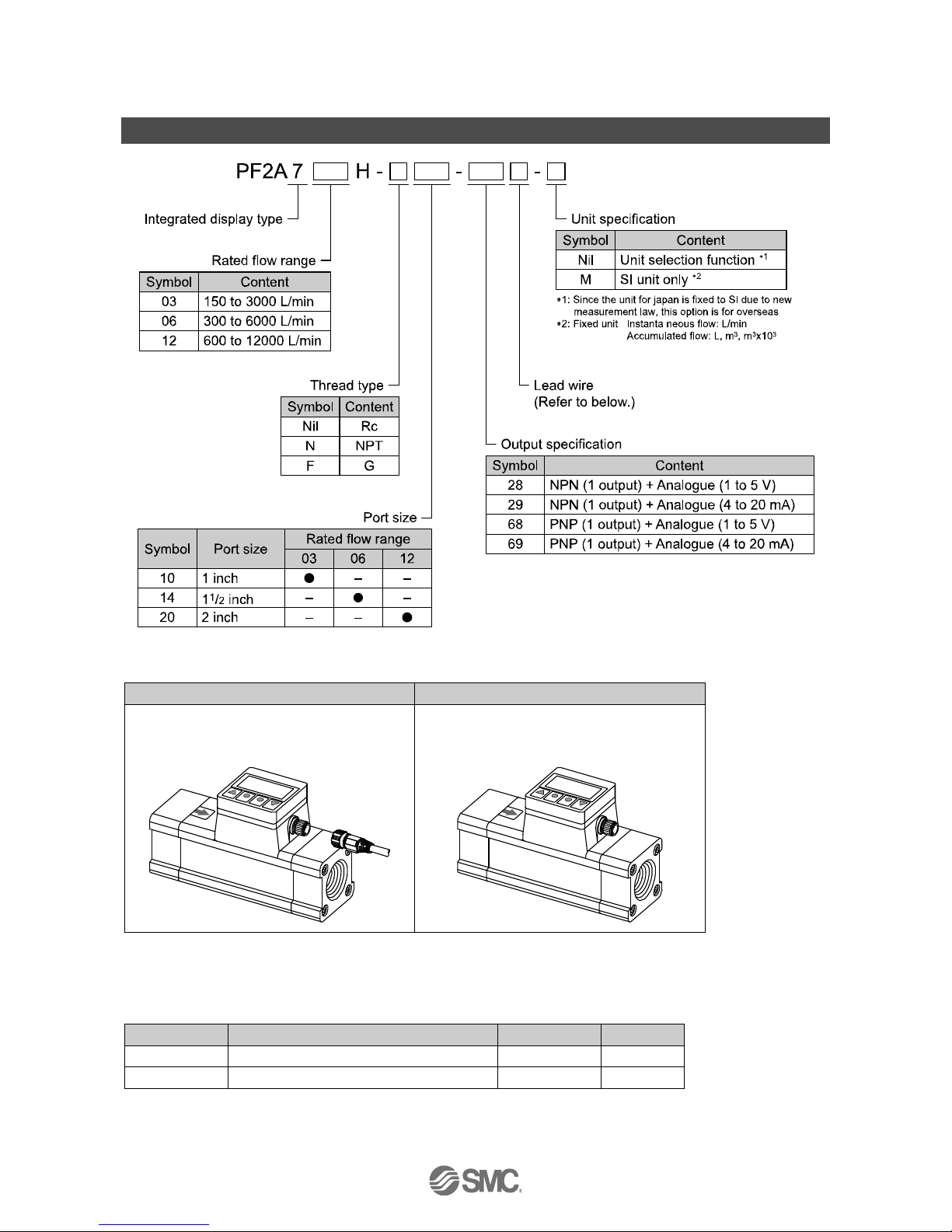
Model indication and How to Order
Lead wire
NIL
N
with lead wire and connector
(Straight, 3 m)
without lead wire
: Lead wire is not assembled with the product, but shipped together.
Accessories/Part number
If an accessory is required separately, order using the following part numbers.
Part number
Description
Remarks
Weight
ZS-37-A
Lead wire with connector (Straight)
Length: 3 m
100 g
ZS-37-B
Lead wire with connector (Right angle)
Length: 3 m
100 g
Page 12
-11-
No.PF※※-OMG0010-G
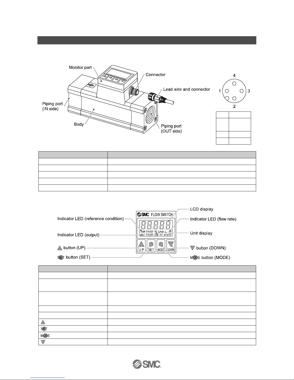
Summary of Product parts
Body
Connector pin
numbers
(On the product)
1
DC(+)
2
Analogue
output
3
DC(-)
4
OUT1
Item
Description
Monitor part
See below.
Piping port
Connected to the fluid inlet at IN side and to the fluid outlet at OUT side.
Body
The body of the product.
Connector
Connector for electrical connections.
Lead wire and connector
Lead wire to supply power and transmit output signals.
Monitor part
Item
Description
LCD display
Displays the flow value, setting mode, and error indication.
Indicator LED (reference condition)
Indicates the reference condition selected. LED is ON (Red) when standard
condition is selected.
Indicator LED (output)
Indicates the output status of OUT1. LED is ON (Red) when OUT1 is ON.
The LED flashes when an over current error occurs.
Indicator LED (flow rate)
Flashes at intervals proportional to the flow rate.
Unit display
Indicates the unit currently selected.
button (
UP)
Selects the mode or increases the ON/OFF Set value.
button (SET)
Press this button to change to another mode and to set a value.
button (MODE)
Moves on to the function selection mode.
button (
DOWN)
Selects the mode or decreases the ON/OFF Set value.
Page 13
-12-
No.PF※※-OMG0010-G
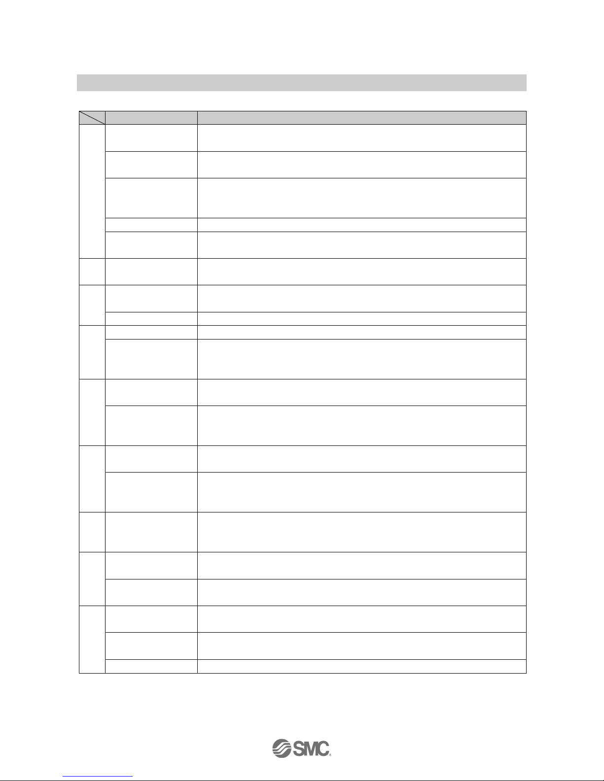
■Definition and terminology
Terms
Meaning
A
Accumulated flow
The total amount of fluid that has passed through the device. If an instantaneous flow of
10 L/min continues for 5 minutes, the accumulated flow will be 10 x 5 = 50 L.
Accumulated pulse
output
A type of output where a pulse is generated every time a predefined accumulated flow
passes. It is possible to calculate the total accumulated flow by counting the pulses.
Analogue output
Outputs a value proportional to the flow rate. When the analogue output is in the range
1 to 5 V, it will vary between 1 to 5 V according to the rate of flow. The same for
analogue output of 4 to 20 mA.
Attachment
A metal part at both sides of the product to connect piping.
Auto-preset
This function calculates and sets the pressure values automatically based on the
on-going operation.
C
Chattering
The problem of the switch output turning ON and OFF repeatedly around the Set value
at high frequency due to the effect of pulsation.
D
Digit
Minimum unit for setting/display is 1 digit. When the minimum unit for setting/display is
5 L/min, 3 digits will be 3 x 5 = 15 L/min
Display flow range
The range which can be displayed by the product with a digital display.
F
Fluid temperature
Range of fluid temperature that can be measured by the product.
F.S.
(Full span, Full scale)
Stands for "full span" or "full scale", and indicates varied analogue output range at rated
value. For example, when analogue output is 1 to 5 V, F.S. = 5[V] - 1[V] = 4[V], (ref.
1%F.S. = 4[V] x 1% = 0.04[V])
H
Hysteresis
The difference between ON and OFF points used to prevent chattering. Hysteresis can
be effective in avoiding the effects of pulsation.
Hysteresis mode
Mode where the switch output will turn ON when the flow is greater than the Set value,
and will turn OFF when the flow falls below the Set value by the amount of hysteresis or
more.
I
Instantaneous flow
The volume of flow per unit of time. If it is 10 L/min, there is a flow of 10 L passing
through the device in 1 minute.
Internal voltage drop
The voltage drop across the product (and therefore not applied to the load), when the
switch output is ON. The voltage drop will vary with load current, and ideally should be
0 V.
M
Minimum
setting/display unit
The resolution of set and display values.
If the minimum setting unit is 1 L/min, the flow can be displayed in 1 L/min units, i.e. 10,
11, 12.
O
Operating humidity
range
The ambient humidity range within which the product will meet all published
specifications.
Operating
temperature range
The ambient temperature range within which the product will meet all published
specifications.
P
Part in contact with
fluid
A part that comes into physical contact with the fluid.
Pressure
characteristics
The amount of variation in the analogue output or display value when the supply
pressure is changed.
Proof pressure
The pressure beyond which the flow switch will be damaged.
Page 14

-13-
No.PF※※-OMG0010-G
Terms
Meaning
R
Rated flow range
The flow range within which the product will meet all published specifications.
Rated pressure range
The pressure range within which the product will meet all published specifications.
Repeatability
Reproducibility of the display or analogue output value, when the flow is repeatedly
changing.
Response time
Time from when the target flow is applied until the flow reaches 90% of the Set value.
S
Setting flow range
The range of ON/OFF threshold values that can be set for flow switches products with a
switch output.
Switch output
An output type that has only 2 conditions, ON or OFF. In the ON condition an indicator
LED will turn on, and any connected load will be powered. In the OFF condition, there
will be no indicator LED and no power is supplied to the load.
T
Temperature
characteristics
The amount of variation in the analogue output or display value when the ambient
temperature is changed.
U
Unit selection function
Function to change the unit in which the value of flow is displayed. Only a product with
this function can change the unit. A product with unit selection function cannot be
purchased if it is used within Japan. Flow is indicated only by SI units in Japan.
W
Window comparator
mode
An operating mode in which the switch output is turned on or off depending on whether
the flow is within the range of 2 Set values.
Page 15

-14-
No.PF※※-OMG0010-G
Mounting and Installation
■Installation
Never mount the product in a location that will be used as a foothold.
The rotation angle of the monitor is 270o, in steps of 90o. Rotating the display part with excessive force will
damage the end stop.
Page 16

-15-
No.PF※※-OMG0010-G
■Piping
Use the product within the specified operating pressure range and temperature range.
Proof pressure is 2.25 MPa.
Connect the piping to the fittings.
Mount the product so that the fluid direction is the same as the arrow indicated on the product.
Never mount the product upside down.
The piping on the IN side must have a straight section of piping whose length is 8 times the piping
diameter or more.
Avoid sudden changes in the piping size on the IN side of the product.
●Connecting the piping
Ensure that the metal piping attachments are tightened to the required torque (refer to the table below).
If the tightening torque is exceeded, the product can be broken. If the tightening torque is insufficient, the
fittings may become loose.
When connecting piping to the product, a spanner should be used on the metal piping attachment only.
Using a spanner on other parts may damage the product.
Avoid any sealing tape from entering inside the piping.
Ensure that there is no leakage from loose piping.
Nominal thread size
Required torque
Rc(NPT)1
36 to 38 Nm
Rc(NPT)11/2
Rc(NPT)2
48 to 50 Nm
Model
Width across flats of
attachment
PF2A703H
55 mm
PF2A706H
65 mm
PF2A712H
75 mm
Page 17

-16-
No.PF※※-OMG0010-G
■Wiring
Connections should only be made with the power supply turned off.
Use separate routes for the product wiring and any power or high voltage wiring. Otherwise, malfunction
may result due to noise.
Ensure that the FG terminal is connected to ground when using a commercially available switch-mode
power supply. When a switch-mode power supply is connected to the product, switching noise will be
superimposed and the product specification can no longer be met. This can be prevented by inserting a
noise filter, such as a line noise filter and ferrite core, between the switch-mode power supply and the
product, or by using a series power supply instead of a switch-mode power supply.
●Connecting the wiring
Align the lead wire connector with the connector key groove, and insert vertically.
Connection is complete when the knurled part is fully tightened. Check that the connection is not loose.
●Connector Pin numbers
When the lead wire with connector designated for the PF2A7 is used, the wire colours will apply as shown
in the diagram.
Connector Pin numbers (on the lead wire)
Pin number
Content
Colour
1
DC(+)
Brown
2
Analogue output
White
3
DC(-)
Blue
4
OUT1
Black
Page 18

-17-
No.PF※※-OMG0010-G
●Internal circuit and wiring example
When the lead wire with connector designated for the PF2A7 is used, the wire colours will apply as shown
in the diagram.
NPN (1 output) + Analogue (1 to 5 V) type
PF2A7H--28-
NPN (1 output) + Analogue (4 to 20 mA) type
PF2A7H--29-
Max. 30 V, 80 mA
Internal voltage drop: 1 V or less
28: Analogue output: 1 to 5 V
Output impedance: 1 kΩ
29: Analogue output: 4 to 20 mA
Max. Load impedance: 250 Ω
PNP (1 output) + Analogue (1 to 5 V) type
PF2A7H--68-
PNP (1 output) + Analogue (4 to 20mA) type
PF2A7H--69-
Max. 80 mA
Internal voltage drop: 1.5 V or less
28: Analogue output: 1 to 5 V
Output impedance: 1 kΩ
29: Analogue output: 4 to 20 mA
Max. Load impedance: 250 Ω
Page 19

-18-
No.PF※※-OMG0010-G
Outline of setting
Power is supplied
The output will not operate for 3 seconds after supplying power.
The identification code of the product is displayed.
Measurement mode
The mode in which the flow is detected and displayed, and the switch output is operating.
This is the basic operating mode; and other modes should be selected for setting
changes and other function settings.
<When instantaneous flow is displayed>
The accumulated flow value can be displayed by pressing the button.
The display digits for accumulated flow can be changed by pressing the button while the
button is pressed.
<When accumulated flow is displayed>
The instantaneous flow value can be displayed by pressing the button.
The display digits for accumulated flow can be changed by pressing the button (unit
flashes.). Press the button to set.
Accumulated flow can be displayed up to 9999999999 L (999999999.9 ft3).
The LCD display displays up to 5 digits at one time. The display is divided into three parts
(upper digits, middle digits and lower digits).
Display unit
Maximum flow
display value
Display digits
Upper digits
Middle digits
Lower digits
L display
[ U_1]
9999999999 L
9999 m3 x 10
3
(9999 L)
999 m
3
(999 L)
999 L
ft display
[ U_2]
999999999.9 ft3
999 ft3 x 10
6
(999. ft3)
999 ft3 x 10
3
(999. ft3)
999.9 ft3
: Operate only the product with unit selection function.
button
press.
Function selection mode
(Refer to page 20)
Other functions
(Refer to page 32)
Page 20

-19-
No.PF※※-OMG0010-G
■List of outputs
Find the diagram of the output required in the table below. Perform settings following the Set value column
on the right.
Switch output diagram
Output mode
Switch
operation
Set value
Instantaneous flow
Instantaneous
output mode
Non-Reverse
output
Set point 2 Set point 1 2
≦
Hysteresis mode
Set point 1 Set point 2
<
Window comparator mode
Reverse output
Set point 2 Set point 1 2
≦
Hysteresis mode
Set point 1 Set point 2
<
Window comparator mode
Accumulated flow
Accumulated
output mode
Non-Reverse
output
Upper digits
Middle digits
Lower digits
Reverse output
Upper digits
Middle digits
Lower digits
Accumulated pulse
Accumulated
pulse output
mode
Non-Reverse
output
No Set value input
Reverse output
No Set value input
1: Hysteresis can be set between "0" and "3% of maximum rated flow". If the difference between Set point 1 and Set point 2 is less than
"6% of maximum rated flow", the maximum Set value of hysteresis is (Set point 1 - Set point 2) divided by 2.
2: When Set point 1 = Set point 2, chattering may occur.
Page 21

-20-
No.PF※※-OMG0010-G
Function selection mode
Function selection mode
In measurement mode, press the button, to display [F_0].
This [F_] indicates the mode for changing each functional setting.
●Default settings
Item
Default Setting
Page
[F_0]
Selection of display mode
[ d_1] Display instantaneous flow
Page 21
Unit selection function
1
[ U_1] L/min
Selection of output mode
[oU1_0] Instantaneous output mode
Input of Set point 1
50% of max. rated flow
[1500] L/min(PF2A703H)
[3000] L/min(PF2A706H)
[6000] L/min(PF2A712H)
Input of Set point 2
Input of hysteresis
2
[ 0]
Selection of switch operation
[oU1_n] Reverse output
Key-lock function
[ UnL] Unlocked
[F_1]
Selection of display mode
[ d_1] Display instantaneous flow
Page 22
[F_2]
Unit selection function
1
[ U_1] L/min
Page 23
[F_3]
Selection of output mode
[oU1_0] Instantaneous output mode
Page 24
Input of Set point 1
50% of max. rated flow
[1500] L/min(PF2A703H)
[3000] L/min(PF2A706H)
[6000] L/min(PF2A712H)
Input of Set point 2
Input of hysteresis
2
[ 0]
[F_4]
Selection of switch operation
[oU1_n] Reverse output
Page 25
[F_5]
Key-lock function
[ UnL] Unlocked
Page 26
[F_6]
Input of Set point 1
50% of max. rated flow
Page 27
Input of Set point 2
50% of max. rated flow
Input of hysteresis
2
[ 0]
[F_7]
Selection of reference condition
[ Anr] Standard condition
Page 30
[F_8]
Accumulated value hold
[ oFF] Not held
Page 31
1: Operate only the product with unit selection function.
2: Setting is available when Set point 1 < Set point 2.
Not displayed when Set point 1≧Set point 2.
Page 22

-21-
No.PF※※-OMG0010-G
Press the button. SI unit only
The product with unit selection function
■[F_0] Initialize mode
Items below can be set one by one.
<Operation>
Press the , and buttons in function selection mode to display [F_0].
Press the button.
Selection of display mode
Refer to page 22.
Unit selection function
Refer to page 23.
: Operate only the product with unit selection function.
Press the button.
Selection of output mode
Refer to page 24.
Press the button.
Input of the Set point
Refer to page 27.
Press the button.
Selection of switch operation
Refer to page 25.
Press the button.
Key-lock function
Refer to page 26.
Press the button.
Setting of initialize mode is completed.
Return to measurement mode.
Page 23

-22-
No.PF※※-OMG0010-G
■[F_1] Selection of display mode
<Operation>
Press the , and buttons in function selection mode to display [F_1].
Press the button.
Selection of display mode
Select the display of instantaneous flow or accumulated flow.
Press the button for select.
[d_1]: display instantaneous flow
[d_2]: display accumulated flow
Press the button.
Press the button.
Setting of display mode is completed.
Return to measurement mode.
Setting of display mode is completed.
Move on to [F_2] Unit selection function.
Page 24

-23-
No.PF※※-OMG0010-G
■[F_2] Unit selection function
Display unit can only be selected for products with unit selection unction.
: This function is not displayed for the model without unit selection function.
<Operation>
Press the , and buttons in function selection mode to display [F_2].
Press the button.
Unit selection function
Press the button for select.
Display
Instantaneous flow
Accumulated flow
[ U_1] L/min
L, m3, m3 x 103
2
[ U_2]
1
CFM
ft3, ft3 x 103, ft3 x 106
2
1: Refer to the table below for the flow rate when [ U_2] is selected.
2: Refer to page 18 for the change of the unit (the display digits) for
accumulated flow.
Press the button.
Press the button.
Setting of unit selection function is completed.
Return to measurement mode.
Setting of unit selection function is completed.
Move on to [F_3] Selection of output mode.
Flow specification when [ U_2] is selected by the unit selection function
Model
PF2A703H
PF2A706H
PF2A712H
Flow
Rated flow range
5.5 to 106.0 CFM
10.5 to 212.0 CFM
21.0 to 423.5 CFM
Instantaneous
flow
Setting/display flow
range
4.5 to 107.0 CFM
9.0 to 213.5 CFM
19.5 to 425.5 CFM
Min. setting/display unit
0.5 CFM
Accumulated
flow
Setting/display flow
range
999999999.9 ft3
Min. setting/display unit
0.1 ft3
Conversion of accumulated pulse
10 ft3/pulse
: Flow rate in the specification is the value at standard condition.
If the display unit standard is changed from standard to normal, use the conversion formula.
Flow rate at standard condition x 0.927 = Flow rate at normal condition
Page 25

-24-
No.PF※※-OMG0010-G
■[F_3] Selection of output mode
<Operation>
Press the , and buttons in function selection mode to display [F_3].
Press the button.
Selection of output mode
Select the switch output mode required referring to the list of outputs (page 19).
Press the button for select.
[oU1_0]: Instantaneous output mode
[oU1_1]: Accumulated output mode
[oU1_2]: Accumulated pulse output mode
Press the button.
Press the button.
Input of the Set point
Refer to page 27.
Setting of output mode is completed.
Move on to [F_4] Selection of switch operation.
Setting of output mode is completed.
Return to measurement mode.
Page 26

-25-
No.PF※※-OMG0010-G
■[F_4] Selection of switch operation
<Operation>
Press the , and buttons in function selection mode to display [F_4].
Press the button.
Selection of switch operation
Select the switch you need referring the list of outputs (page 19).
Press the button for select.
[oU1_n] : Reverse output
[oU1_P]: Non-Reverse output
Press the button.
Press the button.
Setting of switch operation is completed.
Return to measurement mode.
Setting of switch operation is completed.
Move on to [F_5] Key-lock function.
Page 27

-26-
No.PF※※-OMG0010-G
■[F_5] Key-lock function
The key-lock function is used to prevent errors occurring due to unintentional changes of the Set values.
<Operation - How to lock>
Press the , and buttons in function selection mode to display [F_5].
Press the button.
Key-lock function
Press the button to select [ Loc].
[ unL]: Unlock
[ Loc]: Lock
Press the button.
Press the button.
Setting of key-lock function is completed.
Return to measurement mode.
Setting of key-lock function is completed.
Move on to [F_6] Input of the Set point.
<Operation - How to unlock>
Press the button for 3 seconds or longer in measurement mode to display [F_5].
Press the button.
Key-lock function
Press the button to select [ unL].
[ unL]: Unlock
[ Loc]: Lock
Press the button.
Press the button.
Setting of key-lock function is completed.
Return to measurement mode.
Setting of key-lock function is completed.
Move on to [F_6] Input of the Set point.
: Move on to the selection of [F_7] Reference condition selection when [ out1_2] accumulated pulse output mode is selected.
Page 28

-27-
No.PF※※-OMG0010-G
■[F_6] Input of the Set point
When Instantaneous output mode is selected
<Operation>
Press the , and buttons in function selection mode to display [F_6].
Press the button.
Input of the Set point 1
[ n_1] and the current Set value are
displayed in turn.
Press the and button to change
the value referring to list of outputs (page
19).
: When Non-Reverse output has been selected as the switch operation, [P_1] is displayed.
Press the button.
Input of the Set point 2
[ n_2] and the current Set value are
displayed in turn.
Press the and button to change
the value referring to list of outputs (page
19).
: When Non-Reverse output has been selected as the switch operation, [P_1] is displayed.
Press the button.
Input of hysteresis
This setting is available when Set point 1 < Set point 2.
It will not be displayed when Set point 1 ≧ Set point 2.
[ HIS] and the current Set value are
displayed in turn.
Press the and button to change
the value referring to list of outputs (page
19).
: Hysteresis can be set between "0" and "3% of the maximum rated flow". If the difference between the Set point 1 and
Set point 2 is less than "6% of the maximum rated flow", the maximum Set value of hysteresis is (Set point 1 - Set point 2)
divided by 2. If the hysteresis is set to greater than this value, [Error] will be displayed.
Press the button.
Setting of Set point is completed.
Return to measurement mode.
Page 29

-28-
No.PF※※-OMG0010-G
When Accumulated output mode is selected
The value can be set up to 9999999999 L (999999999.9 ft3). The display digits for accumulated flow are
divided into upper, middle, and lower digits. When setting the value, it is divided into upper, middle and lower
digits.
Display
unit
Maximum flow
display value
Display digits
Upper digits
Middle digits
Lower digits
L display
[ U_1]
9999999999 L
9999 m3 x 10
3
(9999 L)
999 m
3
(999 L)
999 L
ft display
[ U_2]
999999999.9 ft3
999 ft3 x 10
6
(999. ft3)
999 ft3 x 10
3
(999. ft3)
999.9 ft3
: Operate only the product with unit selection function.
<Operation>
Press the , and buttons in function selection mode to display [F_6].
Press the button.
Input of the Set point
Input of the Set value for the lower digits
[ n_3]
1
and the current Set value
(Lower digits) are displayed in turn.
Press the and button to change
the value referring to list of outputs (page
19).
Input of the Set value for the middle digits
[ n_3]
1
and the current Set value
(Middle digits) are displayed in turn.
Press the and button to change
the value referring to list of outputs (page
19).
Input of the Set value for the upper digits
[ n_3]
1
and the current Set value
(Upper digits) are displayed in turn.
Press the and button to change
the value referring to list of outputs (page
19).
1: When Non-Reverse output has been selected as the switch operation, [P_3] is displayed.
2: This diagram shows an example when L display ([ U_1]) is selected.
Press the button 3 seconds or longer.
Setting of Set point is completed.
Return to measurement mode.
: Accumulation starts when power is supplied.
Page 30

-29-
No.PF※※-OMG0010-G
When Accumulated pulse output mode is selected
No Set value is input.
[F_6] is not displayed in function selection mode.
The display moves on to the selection of the switch operation in initialize mode.
Page 31

-30-
No.PF※※-OMG0010-G
■[F_7] Reference condition selection
Standard condition or normal condition can be selected.
<Operation>
Press the , and buttons in function selection mode to display [F_7].
Press the button.
Reference condition selection
Press the button for selection.
[ Anr]: Standard condition.
Flow display which is converted in atmospheric pressure at 20 C, 65%R.H.
[ nor]: Normal condition.
Flow display which is converted in atmospheric pressure at 0 C.
: Flow rate in the specification is the value at standard condition.
If the display unit standard is changed from standard to normal, use the conversion formula.
Flow rate at standard condition x 0.927 = Flow rate at normal condition
: When [Anr] is selected, an Indicator LED (reference condition) [ANR] appears on the lower left of the screen.
Press the
or
button.
Setting of reference condition is completed.
Return to measurement mode.
Page 32

-31-
No.PF※※-OMG0010-G
■[F_8] Accumulated value hold
In the default setting, the accumulated value is cleared when the power supply is turned off.
The accumulated value hold function enables the accumulated flow value to be stored in permanent
memory every 4 minutes.
The maximum writable limit of the memory device is 1 million cycles, which should be taken into
consideration.
If the product is operated 24 hours per day, the life will be as follows.
4 minutes x 1 million cycles = 4 million times = approximately 7.6 years
<Operation>
Press the , and buttons in function selection mode to display [F_8].
Press the button.
Accumulated value hold
Press the button for selection.
[ oFF]: Not held
[ on]: Held
Press the
or
button.
Setting of accumulated value hold is completed.
Return to measurement mode.
: The value is stored in memory every 4 minutes. If the power supply is turned off, the accumulated flow value since the last time it
was stored will be lost
When the power supply is turned on again, the accumulated flow count will start from the last value
recorded at B.
Page 33

-32-
No.PF※※-OMG0010-G
Other functions
●Reset of the accumulated flow
When the accumulated flow display is selected, the accumulated flow can be reset to zero.
<Operation>
Press the button for 6 seconds or longer while the button is pressed.
●Reset to the default setting
The product can be returned to the default settings.
<Operation>
Press the , and buttons in function selection mode to display [F_0]
Press the and buttons simultaneously for 3 seconds or longer. The display will change from [F_0]
to [ F_00].
Press the
button, while [ F_00] is displayed, to restore the default settings. The display will then return
to measurement mode.
If the
button is pressed while [ F_00] is displayed, the default settings will not be restored, and the
display will return to [F_0].
Page 34

-33-
No.PF※※-OMG0010-G
Maintenance
How to reset the product after a power cut or forcible de-energizing
The setting of the product will be retained as it was before a power cut or de-energizing.
The output condition is also basically recovered to that before a power cut or de-energizing, but may change
depending on the operating environment.
Therefore, check the safety of the whole installation before operating the product.
Page 35

-34-
No.PF※※-OMG0010-G
Troubleshooting
Troubleshooting
If an operation failure occurs with the product, use the table below to find out the cause of the problem.
If none of the countermeasures seem to be applicable, or a replacement product operates normally when
installed, the product may be faulty. A product can be damaged by the operating environment (system
configuration etc). If the product seems to be faulty, please contact SMC.
■Cross-reference for troubleshooting
Fault
Probable cause
Recommended action
Display
Display is OFF.
Wiring failure.
Correct the wiring.
Connector loose.
Check the connector.
The display is
unstable.
Foreign matter inside.
Install a filter or mist separator at IN side of product.
If there is foreign matter stuck to the mesh, remove it
completely, taking care not to damage the product.
Piping is connected in the wrong
direction.
Install with the mounting direction corresponding to
the flow direction (arrow indicated on the product).
Pulsation in the flow.
Change to a pump that has less pulsation. Install a
tank to reduce the pressure fluctuation. Change the
piping to elastic piping such as rubber tube.
Air leakage.
Check that seal tape has been applied correctly.
Reconnect the pipes with the specified tightening
torque.
The display is not
correct.
Foreign matter inside.
Install a filter or mist separator at IN side of product.
If there is foreign matter stuck to the mesh, remove it
completely, taking care not to damage the product.
Piping is connected in the wrong
direction.
Install with the mounting direction corresponding to
the flow direction (arrow indicated on the product).
An incorrect flow unit was
selected.
Select the appropriate flow unit.
Air leakage.
Check that seal tape has been applied correctly.
Reconnect the pipes with the specified tightening
torque.
The display flashes.
Accumulated flow has exceeded
the maximum value which can be
displayed at one time.
Change the display digits so that the maximum
accumulated flow value can be displayed (page 18).
: Operate only the product with unit selection function
Page 36

-35-
No.PF※※-OMG0010-G
Fault
Probable cause
Recommended action
Output
There is no output.
Wiring failure.
Correct the wiring.
Connector loose.
Check the connector.
Output is unstable.
Foreign matter inside.
Install a filter or mist separator at IN side of product.
If there is foreign matter stuck to the mesh, remove it
completely, taking care not to damage the product.
Piping is connected in the wrong
direction.
Install with the mounting direction corresponding to
the flow direction (arrow indicated on the product).
Pulsation in the flow.
Change to a pump that has less pulsation. Install a
tank to reduce the pressure fluctuation. Change the
piping to elastic piping such as rubber tube.
Air leakage.
Check that seal tape has been applied correctly.
Reconnect the pipes with the specified tightening
torque.
Hysteresis is too narrow.
Increase the hysteresis.
Button
The buttons cannot be
operated.
Key-lock mode is activated.
Cancel the Key-lock function (page 26).
Page 37

-36-
No.PF※※-OMG0010-G
■Error indication
Error Name
Error Display
Error Type
Troubleshooting Method
Excessive
instantaneous flow
Flow has exceeded the upper
limit of the display flow range.
Reduce the flow.
Over current error
The switch output load current
is more than 80 mA (OUT1).
Turn the power off and remove
the cause of the over current.
Then turn the power on again.
System error
The set data has been
changed unexpectedly.
To reset, press the button for
6 seconds or longer while the
button is pressed. Then set all
data again.
The internal circuit could be
damaged.
Stop using and please contact
SMC.
Excessive
accumulated flow
(When [ U_1] is selected)
Exceeds the range of the 2nd
turn of flow indication.
To reset the accumulated flow
value, press the button for
6 seconds or longer while the
button is pressed.
(When [ U_2] is selected)
Accumulated
flow displayed
(flashing)
: If the error cannot be reset after the above measures are taken, then please contact SMC.
Page 38
-37-
No.PF※※-OMG0010-G
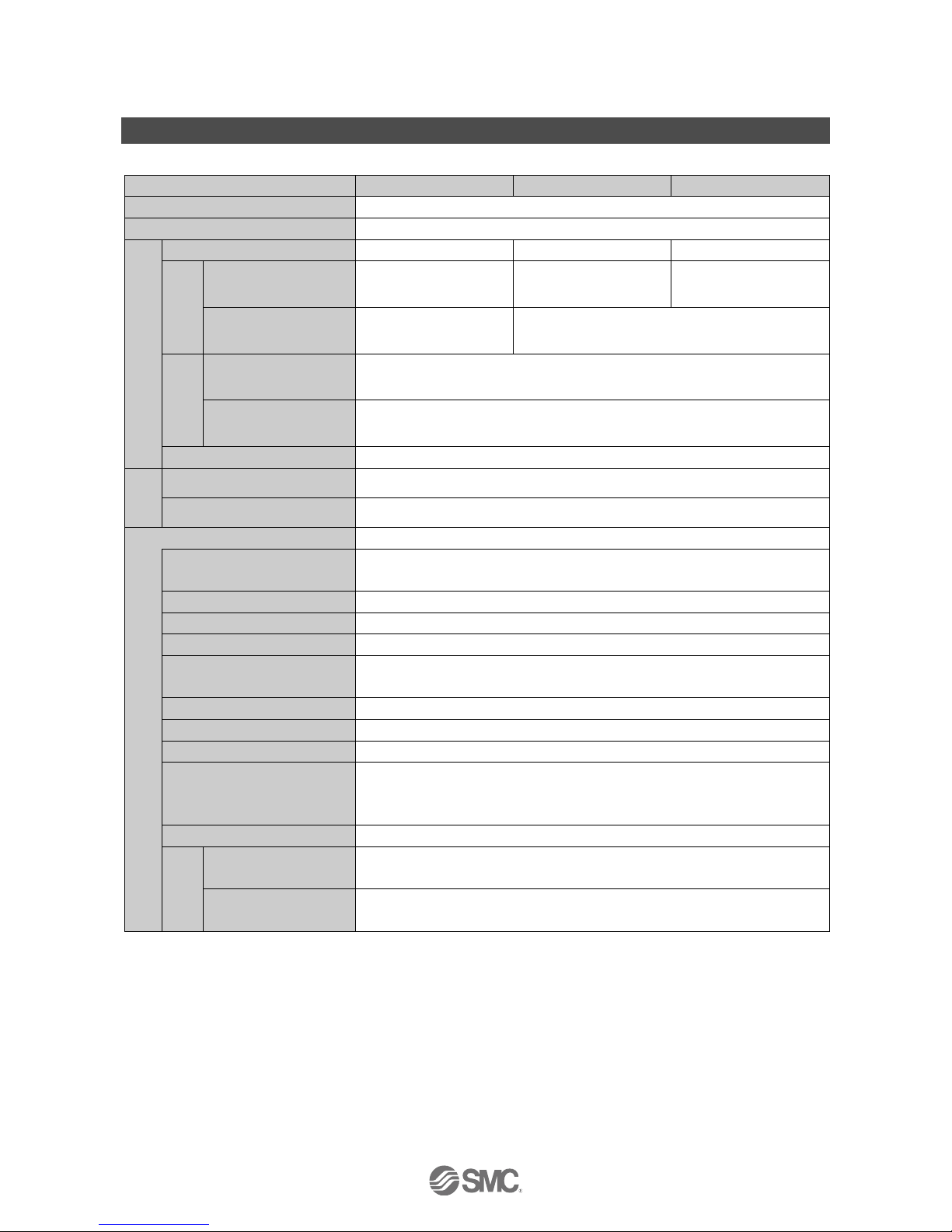
Specifications
■Specifications
Model
PF2A703H
PF2A706H
PF2A712H
Applicable fluid
Dry air and N2
Fluid temperature
0 to 50 C (no freezing or condensation)
Flow
Rated flow range
150 to 3000 L/min
300 to 6000 L/min
600 to 12000 L/min
Instantaneous
flow
Setting/display flow
range
1 2
125 to 3025 L/min
250 to 6050 L/min
550 to 12050 L/min
Min. setting/display unit
5 L/min
10 L/min
Accumulated
Flow
Setting/display flow
range
0 to 9999999999 L
Min. setting/display unit
1 L
Reference condition
3
Standard condition, Normal condition 4
Pressure
Rated pressure range
0.1 to 1.5 MPa
Proof pressure
2.25 MPa
Switch output
NPN open collector output, PNP open collector output
Output mode 3
Instantaneous flow output mode (hysteresis mode, window comparator mode)
Accumulated flow output mode, Accumulated pulse output mode
Switch operation 3
Non-Reversed output, Reversed output
Max. load current
80 mA
Max. applied voltage
30 VDC (NPN output)
Internal voltage drop
NPN output: 1 V or less (at 80 mA)
PNP output: 1.5 V or less (at 80 mA)
Response time
1 s or less
Repeatability
±1%F.S. max.
Accuracy
±1.5%F.S. max.
Hysteresis
Hysteresis mode: Variable 3
Window comparator mode: Variable between "0" and "3%of maximum rated
flow" 3
Output protection
Short circuit protection
Accumulated
pulse
Pulse width
50 ms
Conversion value of
accumulated pulse
100 L/pulse
Page 39

-38-
No.PF※※-OMG0010-G
Model
PF2A703H
PF2A706H
PF2A712H
Analogue output
Voltage output
Output voltage: 1 to 5 V
Output impedance: approx. 1 kΩ
Current output
Output current: 40 to 20 mA
Load impedance: 250 Ω
Accuracy
±3%F.S. max.
Response time
1 s or less
Display
Display accuracy
±1.5%F.S. max.
Display part
5 digits, 7-segments, Colour display: Red
Indicator LED (output)
LED is ON when output is ON
Supply voltage
24 VDC ±10%
Power consumption (no load)
150 mA or less
Environment
Enclosure
IP65
Operating temperature range
Operation: 0 to 50 C, Storage: -25 to 85 C (no freezing or condensation)
Operating humidity range
Operation, Storage: 35 to 85%R.H. (no condensation)
Temperature characteristics
±2%F.S. max. (0 to 50 C, 25 C reference)
Withstand voltage
1000 VAC, for 1 minute between the external terminals and case
Insulation resistance
50 MΩ or more (at 500 VDC)
between external terminals and case
Standards and regulations
CE, RoHS
Port size (Rc, NPT, G)
1
11/2
2
Materials of parts in contact with fluid
A6063, H-NBR, SUS, PPS, PBT, Leaded glass/ptlr/FeNi/OFC, Grease
Weight
Product
1.1 kg
1.3 kg
2.0 kg
Lead wire and connector
100 g
1: Display flow range in the specification is the value at standard condition.
If the display unit is changed from standard [ANR] to normal [nor], use the following conversion formula.
Flow rate at standard condition x 0.927 = Flow rate at normal condition
2: If the flow rate is smaller than the minimum flow of the display range, "0 L/min" is displayed.
3: Selectable by setting.
4: Standard condition: Flow display which is converted in atmospheric pressure at 20 C, 65%R.H.
Normal condition: Flow display which is converted in atmospheric pressure at 0 C.
: The form of the G thread (including the major and minor diameter and pitch of the internal thread) is based on JIS B0202 (ISO228-1).
Products indicated as ISO1179-1 (G thread for hydraulics) or ISO16030 (G thread for pneumatics) are based on JIS B0202
(ISO228-1) for effective depth of thread, seat surface area, surface roughness and squareness.
For ISO1179-1 (G thread for hydraulics), the withstand pressure is specified for each product. SMC do not guarantee the withstand
pressure specified in ISO1179-1, ISO1179-2, ISO1179-3, or ISO1179-4.
For ISO16030 (G thread for pneumatics), the withstand pressure is specified for each product. SMC do not guarantee the withstand
pressure specified in ISO16030.
Lead wire Specifications
Sheath
Finished outside diameter
approx. 4 mm
Material
Oil-resistant PVC
Insulator
Colours
Brown, White, Black, Blue
Outside diameter
approx. 1.14 mm
Conductor
Nominal cross section area
AWG23
Outside diameter
approx. 0.72 mm
Page 40
-39-
No.PF※※-OMG0010-G
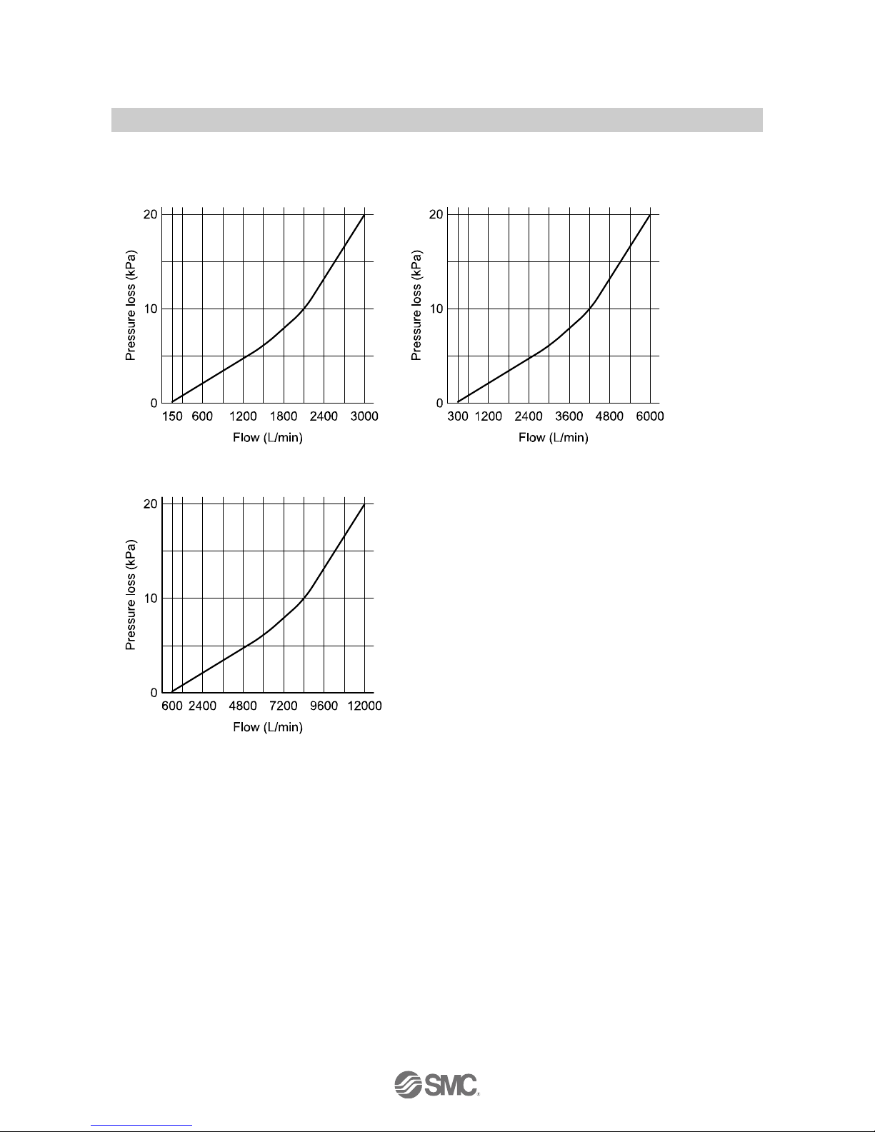
■Characteristics data
●Flow characteristics (pressure loss)
PF2A703H
PF2A706H
PF2A712H
Page 41

-40-
No.PF※※-OMG0010-G
●Analogue output
A B
Voltage output
1 V
5 V
Current output
4 mA
20 mA
Model
Rated flow range
Min.
Max.
PF2A703H
150 NL/min
3000 NL/min
5.5 CFM
106.0 CFM
PF2A706H
300 NL/min
6000 NL/min
10.5 CFM
212.0 CFM
PF2A712H
600 NL/min
12000 NL/min
21.0 CFM
423.5 CFM
: Analogue output is based on the rated flow range at normal condition.
Displayed flow range is based on standard condition.
Therefore, the range of rated flow and the displayed flow are different..
At analogue output mode, the output analogue value varies by switching the mode (normal condition ↔ standard condition).
Use the formula below when the analogue output is used during standard condition.
Flow rate at normal condition ÷ 0.927 = Flow rate of standard condition
Page 42

-41-
No.PF※※-OMG0010-G
■Dimensions (in mm)
PF2A703H/706H/712H
Model A B C D E F
G
PF2A703H
55 mm
160 mm
40 mm
92 mm
67 mm
55 mm
Rc1, NPT1, G1
PF2A706H
65 mm
180 mm
45 mm
104 mm
79 mm
65 mm
Rc11/
2,
NPT11/
2,
G11/2
PF2A712H
75 mm
220 mm
55 mm
114 mm
89 mm
75 mm
Rc2, NPT2, G2
Model H I
J
PF2A703H
36 mm
M5 x 0.8
8 mm
PF2A706H
46 mm
M6 x 1
9 mm
PF2A712H
56 mm
M6 x 1
9 mm
Page 43

-42-
No.PF※※-OMG0010-G
Lead wire and connector (Straight): ZS-37-A
Lead wire and connector (Right angle): ZS-37-B
Dimensions of rotating monitor part
Page 44

No.PF※※-OMG0010-G
Revision history
A: Full scale revision due to the change of the
format and addition of items.
B: Contents changed due to the change of the
format.
C: Revision.
D: Contents revised in several places.
E: Modified errors in text.
F: Modified errors in text.
G: Modified errors in text. [September 2017]
4-14-1, Sotokanda, Chiyoda-ku, Tokyo 101-0021 JAPAN
Tel: + 81 3 5207 8249 Fax: +81 3 5298 5362
URL http://www.smcworld.com
Note: Specifications are subject to change without prior notice and any obligation on the part of the manufacturer.
© 2011-2017 SMC Corporation All Rights Reserved
 Loading...