

Page 1

PAB-OM-H005-C
Operation Manual
Date of issue:28
th
Jan. 2004
Process pump
PAF3413
Page 2

PAB-OM-H005-C
- 1 -
Contents
1. Precautions for handling
・・・・・・・・・・・・・・・・・・・・・・
P2
2. Precautions for installation
・・・・・・・・・・・・・・・・・・・・・・
P3
3. Description and function of
individual port
・・・・・・・・・・・・・・・・・・・・・・ P3
4. How to use
・・・・・・・・・・・・・・・・・・・・・・
P4
5. Maintenance and check
・・・・・・・・・・・・・・・・・・・・・・
P4
6. Specification and how to
order
・・・・・・・・・・・・・・・・・・・・・・ P5~6
7. Discharge capability
・・・・・・・・・・・・・・・・・・・・・・
P7~8
8. Troubleshooting
・・・・・・・・・・・・・・・・・・・・・・
P9~10
9. Construction and operating
principle
・・・・・・・・・・・・・・・・・・・・・・ P11
10. Operating principle
・・・・・・・・・・・・・・・・・・・・・・
P12
11. Sensor mounting
(leakage sensor)
・・・・・・・・・・・・・・・・・・・・・・ P13
12. Sensor mounting
(stroke sensor)
・・・・・・・・・・・・・・・・・・・・・・ P14
Safety instructions
This operation manual indicates the precautions for safety use of process pump with the level of
potential hazard as follows. Those precautions contain the content essential to keep safety.
!
Warning
Operator error could result in serious injury and loss of life.
!
Caution
Operator error could result in injury or equipment damage.
Page 3

PAB-OM-H005-C
- 2 -
1. Precautions for handling
!
Warning
1) Operating environment
・When dangerous fluid or fluid possibly harmful to human is used, take measure to isolate human from
the pump. Should the external leakage of transported fluid come out, the serious damage to human
could be caused.
・When flammable or highly corrosive fluid is transported, keep the fire source away from the pump.
Otherwise, the fire and explosion could be caused.
・Prevent splash of corrosive fluid or other solvents to the external face of the pump.
・If attachment of unknown liquid is found on the external face of the pump, do not touch it without care.
2) External leakage of transported fluid
・When flammable or dangerous fluid is transported, keep the fire source and corrosive material away
from the pump. For this purpose, prepare the vessel for possible leakage and take other measures to
prevent contact with the fire source and corrosive material. Otherwise, the fire and explosion could
be caused.
・During operation of pump, the transported fluid could leak due to life out of the diaphragm. In this
case, take prevention for the leakage to avoid adverse effect to human or facility.
・Do not touch the leakage of fluid without care. If the fluid has high temperature or is chemical, the
contact could result in burn and other injuries.
3) Disassembly
・Do not disassemble the pump.
!
Caution
1) Quality of supplied air
・Mount the filter with filtration of approx. 0.01μ. For the quality of air to be used, refer to Compressed
Air Cleaning Equipments Catalog No. 5*
*Typical circuit shown on No.5
Compressor→HAW(after cooler)→AT(air tank)→AFF(main line filter)→IDF(refrigerating air dryer)→
AM(mist separator)→AMD(micro mist separator)→PAF
・If the amount of foreign materials generated from air supply (carbon powder etc.) is large, mount
super mist separator etc. to reinforce prevention for attachment of dust. Deposit of foreign materials
could increase resistance and prevent smooth operation.
2) Quality of transported fluid
・If it is known solid materials enter the transported fluid, mount the filter with filtration of 0.2mm at least
on fluid in.
3) Life and replacement
・Suspend operation and replace the diaphragm before it reaches the end of life. If the diaphragm
breaks, the transported fluid leaks inside the pump and exhaust port, and the internal parts of the
pump are damaged and the air blows FLUID OUT port.
Calculation of life of diaphragm(depending on operating conditions)
50 million cycles(referential life cycle)
Referential life date=
Frequency of solenoid valve(Hz) X 60(sec) X operating time per day(hour) X 60(min.)
・The discharge amount per one cycle is about 0.050 l when there is no piping resistance. The pump
internal capacity is about 100 m l.
4) Pilot air
・Confirm the supplied pilot air is within specified range from 0.2 to 0.5MPa. The air out of this range
could cause malfunction, stop of operation, damage of internal parts and external leakage.
5) Discharge amount and suction head
・Given discharge rate and suction head are for the condition with fresh water, room temperature,
atmospheric pressure and no piping. Thus, they are varied by physical characteristic of transported
fluid, and in some cases, enough suction head can’t be obtained.
6) Max. discharge amount
・Given max. discharge rate is for the condition with supplied pressure of 0.5MPa, piping I.D. of
10mm,piping length of 0.5m, solenoid valve VQZ3000 mounted, cycle of 4Hz and no load.
7) Operating temperature
・The pump is available from 0 to 90
O
C, but should be cared not to freeze.(Avoid exposure to heat
cycle.)
Page 4
PAB-OM-H005-C
- 3 -
2. Precaution for installation
!
Caution
1) Mounting
・Only horizontal mounting is available. When the pump is not mounted horizontally with its bottom
faced down, it may cause sucking failure.
・Use two M5 bolts (four M6 bolts for foot bracket) to mount the pump. If the bolts are not tightened
firmly, the pump could be exposed to the vibration and eventually damage.
2) Piping
・Perform flushing enough for piping to avoid intrusion of cutting chips and sealant debris created by
screwing the piping and fitting. If the tape is used for sealing, leave two threads exposed.
3) Material of fitting
・The threaded part is made of resin. Thus, do not tighten the metal fitting to avoid collapse of the
thread.
4) Tightening torque
・Insufficient tightening torque could cause external leakage and excessive one could damage threaded
part and parts. Keep adequate value for tightening.
3. Description and function of individual port
Suction port(FLUID IN) …To suck transported fluid. Connect suction piping.
Discharge port(FLUID OUT)…To discharge fluid sucked inside the pump. Connect discharge piping.
Pilot air port(P1, P2) …To supply and exhaust the air at set pressure. Connect air piping.
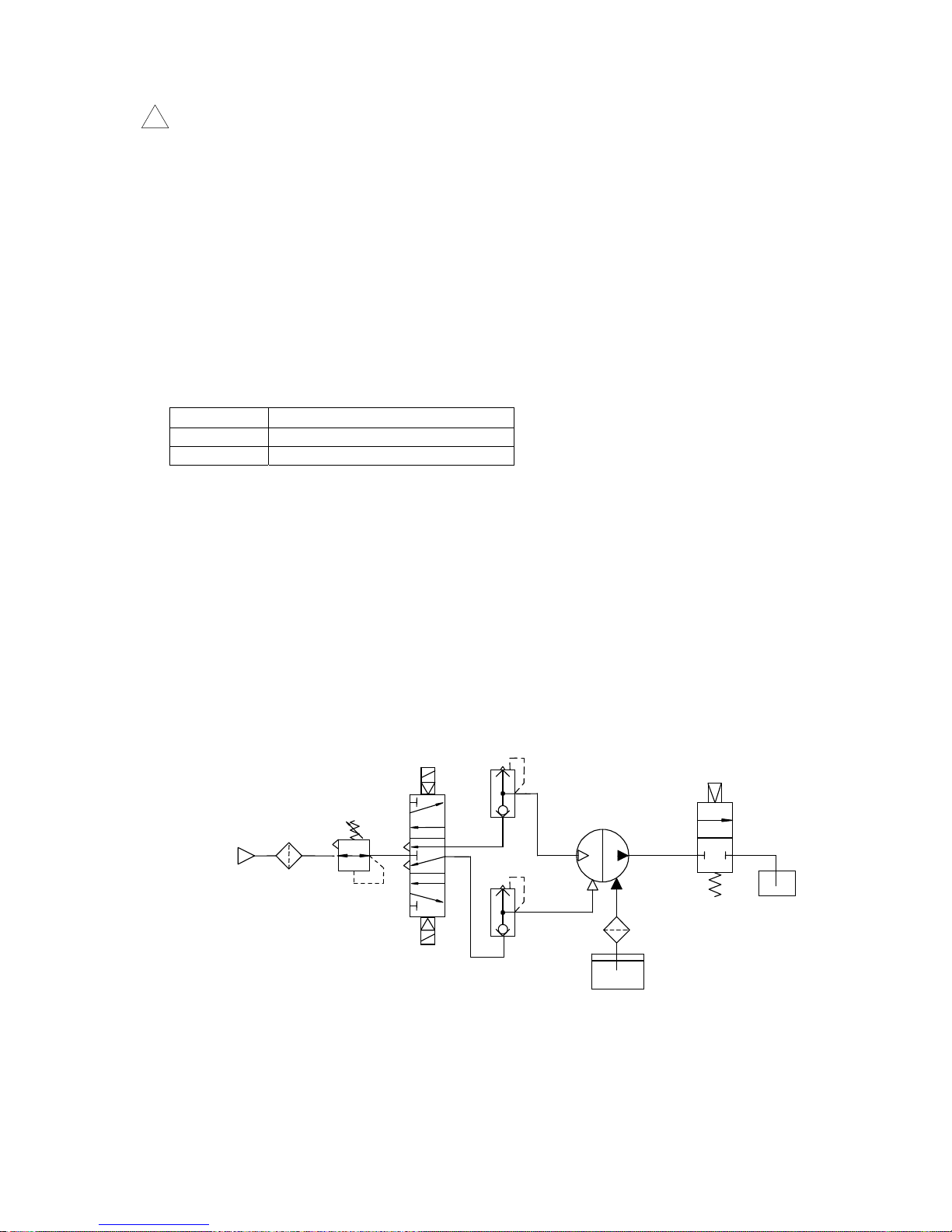
●Typical circuit
Thread size
Adequate tightening torque(N・m)
Rc1/8 0.4 to 0.5
Rc3/8 2 to 2.5
FLUID
OUT
FLUID
IN
Valve
Strainer
Transported fluid
5 port solenoid valve
(Exhaust center)
Regulator
Air filter
Air supply
Process pump
P1
P2
Quick exhaust valve
Page 5

PAB-OM-H005-C
- 4 -
4. How to use
!
Caution
1) Start and stop
・Connect the supply and exhaust port ”P1”, “P2” with air piping and suction port “FLUID IN” and
discharge port “FLUID OUT” with transported fluid piping respectively. If it is concerned molecular of
transported fluid permeates PTFE diaphragm and gives adverse effect on the solenoid valve, mount
compatible quick exhaust valve before the solenoid valve to prevent exposure to exhausted fluid.
・Set pilot air pressure in a range from 0.2 to 0.5MPa.
Keep the valve at discharge side open. When the solenoid valve at air supply side is energized, the
air is supplied for “P1” and “P2” and the pump starts. The solenoid valve is adjusted to switch at 2 to
4Hz. Then, after a while, the fluid starts flowing from suction port “FLUID IN” to “FLUID OUT”.
・To stop the pump, cut off the supply of air and exhaust the air inside the pump.
2) Adjustment of discharged flow rate
・The discharged flow rate is adjusted by opening and shutting level of the valve connected at
discharge side or solenoid valve. Sudden close of these valves could cause surge and shorten the
life of pump remarkably, and so must be avoided.
5. Maintenance and check
1) During operation
・During operation of pump, it is necessary to check leakage of fluid and air and operating condition
periodically. If any abnormality or concern is seen, stop the pump immediately and contact local
supplier or SMC.
・When touching the pump for maintenance, put the protective tool such as glove which isn’t affected by
transported fluid to prevent burn.
2) During stop
・If the pump is stopped for a few hours, exhaust the air at supply side.
・If the pump is left unused for extended period, clean inside of the pump to prevent adherence and
sticking of transported fluid over the time which could cause abnormal operation.
3) Check and repair
・Replace the diaphragm before it reaches referential life cycles(specified cycles). If the pump is
continued after the life of diaphragm, the check valves of wetted part as well as the diaphragm are
deteriorated and operating failure could be caused.
Page 6

PAB-OM-H005-C
- 5 -
6. Specifications and how to order
●Specifications
Model PAF3413
Main fluid
suction/discharge
port
Rc・G・NPT 3/8, 1/2 tube piping,
With nut
Port size
P1・P2 Rc・G・NPT 1/8
Body new PFA
Diaphragm/Packing PTFE
Material of
wetted part
Check valve new PFA, PTFE
Discharge rate 1 to15L/min
Average discharge pressure 0 to 0.4MPa
Pilot air consumption
Max. 230L/min(ANR)
Note 2
)
Dry
Max. 1m(Inside of the pump is dry.)
Suction
head
Wet
Max. 4m(The pump contains the fluid.)
Transported fluid temperature
0 to 90℃(No freezing)
Ambient temperature
0 to 70℃(No freezing)
Recommended operation cycle 2 to 4Hz
Pilot air pressure 0.2 to 0.5MPa
Proof pressure 0.75MPa
Mounting direction
Horizontal(mounting hole at bottom)
Weight 1.3kg
Note 1) Above values are at ordinary temperature and with fresh water.
Note 2) Calculated for atmospheric condition, 20
O
C (ANR)
Page 7

PAB-OM-H005-C
- 6 -
●How to order
Female thread,Tube piping
With nut
P A F
341
3
※※
● Operation type
● Tube port
● Female thread
B
● Option
Thread style
NIL
N
F
Rc
NPT
G
Port size
03 3/8
Tube size
P13 1/2
Thread style
NIL Rc
NPTN
FG
NIL Body
B
With foot
3 Air operated type
Symbol Style Symbol Port size
Symbol Option
Symbol Operation type
Symbol Main fluid port Symbol
Style
P A F
341
3
S
1
Operation type ●
B
● Option
NIL Body
B
With foot
3 Air operated type
Symbol Option
Symbol Operation type
Symbol Fitting type
1LQ1
● Fitting size
In side Out sideSymbol
13
1319
1913
19
4
5
4 5
5 4
● Thread style
Symbol Style
NIL Rc
N
F
NPT
G
Fitting type ●
S ※※
Page 8

PAB-OM-H005-C
- 7 -
7. Discharge capability
1) Flow characteristic
With reference to flow characteristic graph (shown below), operating condition of the pump can be set.
Recommended typical condition A:Calculate air pilot pressure in case of discharge rate 6L/min and
pressure 0.25MPa
<Assumption; Fresh water (viscosity 1mPa・s , specific gravity1.0)is used as transported fluid>
1. Plot the cross point between line with discharge rate 6L/min and line with pressure 0.25MPa.
2. Calculate pressure of transported fluid based on the point. In this example, the point is located
between discharge curves (full line) with 0.3MPa and 0.4MPa and it can be found required air
pressure at this point is approx. 0.38MPa in proportional relation.
!
Caution
・The above flow characteristic graph is for fresh water(viscosity 1mPa・s , specific gravity 1.0). Thus,
if the fluid with higher viscosity such as oil is used, convert the fluid to fresh water with reference to
viscosity characteristic graph.
・The discharge amount is affected by characteristic of transported fluid (viscosity, specific gravity,
concentration of slurry) and operating conditions (temperature, pump head, transporting distance)
etc. and should be confirmed before use.
・In the application where the back pressure is applied from discharge port “FLUID OUT”, the result of
(pilot air pressure − back pressure, i.e. pressure difference)is pilot air pressure on the graph.
Also, it should be noted discharge amount decreases compared with normal condition.
・If required output of compressor is calculated from air consumption, consider the output is 0.75kW per
air consumption of 100L/min (ANR) for reference.
2Hz 流量特性
0
0.1
0.2
0.3
0.4
0.5
0 5 10 15 20
流量(L/min)
吐出圧力(MPa)
SUP=0.5MPa
0.4MPa
0.2MPa
0.3MPa
Flow characteristics at 2Hz
Discharge pressure [ MPa ]
Discharge rate [L/min]
4Hz 流量特性
0
0.1
0.2
0.3
0.4
0.5
0 5 10 15 20
流量(L/min)
吐出圧力(MPa)
SUP=0.5MPa
0.4MPa
0.3MPa
0.2MPa
Discharge pressure [ MPa ]
Discharge rate [L/min]
Flow characteristics at 4Hz
Page 9

PAB-OM-H005-C
- 8 -
2) Viscosity characteristic
With reference to viscosity characteristic graph (shown below), discharge amount of transported fluid
with higher viscosity can be calculated.
Recommended typical condition B:Calculate discharge amount of fluid with viscosity 100mPa・s in
case of discharge rate 4.5L/min and discharge pressure 0.1MPa.
1. Find ratio of discharge amount to fresh water for the fluid with viscosity 100mPa・s from the graph.
Then, it is found to be 45%.
2. After that, convert it to discharge amount of fresh water.
Since discharge rate 45% of fresh water is equal to 4.5L/min of the fluid, with the following
calculation;
4.5L/min÷0.45=10L/min
it is found discharge rate 10L/min is necessary for fresh water.
3. Then, refer to flow characteristic graph and calculated air pilot pressure.
Referential viscosity of various fluid(at 20 ℃)
!
Caution
・The viscosity of fluid is affected by operating conditions(temperature, transporting distance etc.)and
fluctuation of ambient temperature.
・Viscosities up to 1000 mPa・s can be used.
粘 度(mPa・s)
清水に対する吐出量の比率(%)
1000100101
100
90
80
70
60
50
40
30
20
10
0
Viscosit
y(
mPa・s
)
Ratio of dischar
g
e amount to fresh water
(
%
)
Water
Vegetable
oil
Lubricant
Silicone oil
Cutting oil
45
Medical barium
Tomato juice
Woosterource
Honey
Viscosity
(mPa・s)
1
60 ~ 80 340 950
1500 3150
980
0
0
10
0
10
00
10
000
150
2
~
3000
2
650
4500
Page 10

PAB-OM-H005-C
- 9 -
8. Troubleshooting
If any abnormality is found, perform check along with the following list. If the abnormality can’t be
eliminated, return the pump to SMC.
!
Warning
Exhaust dangerous fluid out of the pump before check.
・Do not return the pump with dangerous fluid left. Be sure to substitute it with DI water.
Otherwise, the fluid could cause burn and other damages on human during transportation.
Trouble Possible cause Remedy
1) Supply of air can’t move
the pump.
・Internal air piping is clogged with
dust.
・Suction side(FLUID IN)or discharge
side(FLUID OUT) is closed or has
large resistance.
・Defect inside the body.
・Insufficient supplied air pressure.
・Intrusion of foreign materials into
pump chamber.
・Damaged diaphragm.
・Cleaning or replacement of
pilot air switching part.
・Review of piping at suction or
discharge side and removal
of restrictor.
・Replacement of pump.
・Supply of air at adequate
pressure.
・Cleaning.
・Replacement of pump.
The pump
doesn’t
suck.
・Check valve is clogged.
・Check valve is damaged or worn.
・The filter at suction side(FLUID IN)
is clogged.
・Excessive required suction head.
・Incorrect mounting direction.
・The diaphragm is damaged or
comes off.
・Sealing failure of fitting at suction
side(FLUID IN).
・Excessive viscosity of transported
fluid.
・Incorrect insertion of check valve.
・Cleaning.
・Replacement of pump.
・Cleaning of filter.
・Reduction to suction head
covered by the pump.
・Remounting in normal
direction.
・Replacement of pump.
・Secure mounting of seal.
・Use of fluid with lower
viscosity.
・Remounting in correct
direction.
2) The pump
starts, but
doesn’t
discharge.
The pump
sucks, but
doesn’t
discharge
・Check valve or fitting at discharge
side(FLUID OUT) is clogged.
・Cleaning.
Page 11

PAB-OM-H005-C
- 10 -
3) The discharge amount is
insufficient.
・Check valve at suction side(FLUID
OUT) or discharge side(FLUID
OUT) is clogged.
・Excessive viscosity of transported
fluid.
・Excessive required suction or
discharge pressure.
・The filter of suction side(FLUID IN)
is clogged.
・The filter of discharge side(FLUID
OUT) is clogged.
・Insufficient air supply.
・Too small port size of transported
fluid piping.
・Application of back pressure from
discharge side(FLUID OUT).
・Cleaning.
・Non-conformance.
・Reduction of required head.
・Cleaning or replacement.
・Cleaning or replacement.
・Supply of air at adequate
pressure.
・Increase of air supply.
・Removal of back pressure or
increase of supplied air
pressure.
4) A lot of air bubble come
out from discharge side
(FLUID OUT)
・Air is sucked by suction side(FLUID
IN).
・Sealing failure of fitting at suction
side(FLUID IN).
・Damaged diaphragm.
・Looseness of diaphragm fixing bolt.
・Prevention of suction.
・Secure mounting of seal.
・Replacement of pump.
・Retightening.
5) Transported fluid comes
out from exhaust port of
solenoid valve.
・Damaged diaphragm. ・Replacement of pump.
6) Transported fluid or air
leaks from jointed part to
outside.
・The diaphragm is damage or comes
off.
・Looseness of bolts which fix the
parts at each port (port, elbow fixing
flange, port fixing flange, air port
cover).
・Replacement of pump.
・Retightening.
Page 12

PAB-OM-H005-C
- 11 -
9. Construction and operating principle
First, the air is supplied for switching valve mounted outside the pump. Then the signal is given from
timer etc. and the air starts flowing into each actuating chamber in turn and moves diaphragm up and
down.
Air supply port
(AIR SUP)
Discharge port
(FLUID OUT)
Suction port
(FLUID IN)
Pump chamber B
Diaphragm B
Actuating
chamber A
Actuating
chamber B
Diaphragm A
Pump chamber A
Check valve
5 port solenoid valve
P1 P2
Page 13

PAB-OM-H005-C
- 12 -
Actuating
chamber A
Actuating
chamber B
Discharge
port
Pump
chamber B
Pump
chamber A
Suction
port
Pump
chamber A
Diaphragm
Suction
port
Discharge
port
Pump
chamber B
Actuating
chamber A
Actuating
chamber B
Fluid flow Air flow
10. Operating principle
As shown on Fig. 1, when the air flows into actuating chamber A, the fluid is discharged away from
the pump chamber A and sucked toward the pump chamber B.
Then, the solenoid valve is switched by timer etc. and the reverse operation is performed. (Fig. 2).
The pump repeats these two operations in turn and performs suction and discharge of fluid
continuously.
Fig. 1 Fig. 2
Page 14

PAB-OM-H005-C
- 13 -
11. Sensor mounting (leakage sensor)
Series PAF can have a sensor for detecting diaphragm breakage. If liquid leaks in the pump through
the diaphragm, this sensor responded it, and detects diaphragm breakage.
<Mounting>
1. Remove the round head Philips screws below the AIR SUP port of the pump. Then, remove the
leakage sensor cover, plug, and O-ring (Fig. 1). The O-ring, leakage sensor cover, and round head
Philips screws are used again later. Do not throw them away.
2. Mount the O-ring again to the part from which it is removed, and insert 2 leakage sensors there.
Put the leakage sensor cover back to the part with the round head Philips screws (tightening torque:
0.125N・m) (Fig. 2).
3. Insert optical fibers to the amplifier, and set the amplifier to “Percent tuning”. At this time, the ratio at
the threshold level is set to 20~25%
(※1)
.
Name of components
①
O-ring 2pcs
②
Plug 2pcs
③
Leakage sensor cover 1pcs
④
Round head Philips screws
2pcs
⑤
Leakage sensor 2pcs
※1 This value is a reference value. Please inquire of local supplier or SMC when you cannot confirm
operation even if the proportion at the threshold level is set.
※2 Two sets of liquid-leakage sensor "KT-PAF3-47" are required for one pump.
Also, one piece of amp "HPX-AG00-1"manufactured by Yamatake Corporation is required for one
sensor to detect the liquid leakage (two amps are required in total).
Fig. 1
①
③
FLUID OUT
FLUID IN
P1, P2
②
④
Fig. 2
①
⑤
③
④
(※2)
!
Caution
Tighten two ④round head Philips screws
with torque
0.125N・m.
Page 15

PAB-OM-H005-C
- 14 -
12. Sensor mounting (stroke sensor)
Series PAF can detect the stroke end of a diaphragm with an optical sensor. If this information is sent
to an air-operate solenoid valve as feedback, a diaphragm can operate full-stroke stably even with an
external air operate solenoid valve.
<Mounting>
1. Remove round head Philips screws at P1, P2 port of the pump. Then, remove the air port cover, plug,
and O-ring (Fig. 1). The O-ring, air port cover, and round head Philips screws are used again later.
Do not throw them away.
2. Insert two stroke sensors with the O-ring to the part from which the air port cover etc were removed,
and put the air port cover back with round head Philips screws (tightening torque: 0.125N・m(Fig. 2).
The one of the two stroke sensors floodlights and the other receives the light. Therefore, the stroke
sensors must be inserted to the amplifier so that those two sensors’ light axis can face to each other
(Fig. 3). After inserting the sensors, insert optical fibers to the amplifier to adjust the amount of light.
3. Set the amplifier to “Percent tuning”. At this time, the ratio at the threshold level is set to 20~25%
(※1)
.
Name of components
①
O-ring 4pcs
②
Plug 4pcs
③
Air port cover 2pcs
④
Round head Philips screws 6pcs
⑤
Stroke sensor 2pcs
※1 This value is a reference value. Please inquire of the shop and our business member when you
cannot confirm operation even if the proportion at the threshold level is set.
※2 Two sets of stroke sensor "KT-PAF3-48" are required for one pump.
Also, one piece of amp "HPX-AG00-1"manufactured by Yamatake Corporation is required for one
sensor to detect the stroke end of a diaphragm (two amps are required in total).
Fig. 1
①
②
③
④
FLUID IN
FLUID OUT
P1, P2
Fig. 2
⑤
Fig. 3
Floodlights
Receives
the light
Light axis
Light axis
(※2)
!
Caution
Tighten two ④round head Philips screws
with torque
0.125N・m.
 Loading...