

SMC Networks MWB 100-UT, MWB 100TF-UT, MWB 32TF-UT, MWB 32 TN-UT, MWB 100TN-UT Operation Manual
...
Doc. no.MWB*-OM0078Q
PRODUCT NAME
Lock unit
MODEL / Series / Product Number
MWB*32&100-UT-*
MWB*32&100TN-UT-*
MWB*32&100TF-UT-*

Contents
Safety Instructions P. 3
1. Product Specifications P. 5
1-1. Lock unit specifications
1-2. Stop accuracy
1-3. Precautions on model selection
2. Installation and Handing P. 8
2-1. Air supply
2-2. Design
2-3. Mounting
2-4. Operating environment
2-5. Pneumatic circuit
2-6. Adjustment and Operation
3. How to use P. 15
3-1. Usage
3-2. Lock release mechanism
4. Maintenance P. 18
4-1. Checks
4-1-1. Inspection points
4-1-2. Inspection interval
5. Troubleshooting P. 19
6. Construction P. 24
-1-
Warning
1. The comp ati bil ity of the product is the responsibil ity of t he pers on wh o desig ns t h e eq uipme n t or
4. Contact SMC beforehand and take special consideration of safety measures if the product is to
Safety Instructions
These safety instructions are intended to prevent hazardous situations and/or equipment damage.
These instructions indicate the level of potential hazard with the labels of “Caut ion, ” “Warning” or “Danger.”
They are all important notes for safety and must be followed in addition to International Standards
(ISO/IEC)*1) , and other safety regulations.
*1) ISO 4414: Pneumatic flu id pow er -- General rules relating to systems.
ISO 4413: Hydraulic fluid pow er -- General rules relating to systems.
IEC 60204-1: Safety of machinery -- Electrical equipment of machines .(Part 1: General requirements)
ISO 10218: Manipulating industrial robots -Safety.
etc.
Caution
Warning
Danger
Caution indicates a hazard with a low level of risk which, if not avoided, could result
in minor or moderate injury.
Warning indicates a hazard with a medium level of risk which, if not avoided, could
result in death or serious injury.
Danger indicates a hazard with a high level of risk which, if not avoided, will result
in death or serious injury.
decides its specif i cat i ons.
Since the product specified here is used under various operating conditions, its compatibility with specific
equipment must be decided by the person who desig ns the equ ipment or dec ides its spec ifications based o n
necessary analysis and test results.
The expected performance and safety assurance of the equipment will be the responsibility of the person who
has determined its compatibility with the product.
This person should also continuously review all specifications of the product referring to its latest catalog
information, with a view to giving due consideration to any possibility of equipment failure when configuring the
equipment.
2. Only personne l with appr opr iate training should operat e m achinery and equipment.
The product specified here may become unsafe if handled incorrectly.
The assembly, operation and maintenance of machines or equipment including our products must be
performed by an operator who is appropriately trained and experienced.
3. Do not service or attempt to remove product a nd machinery/equipment until safety is confirmed.
1.The inspection and maintenance of machinery/equipment should only be performed after measures to
prevent falling or runaway of the driven objects have been confirmed.
2.When the product is to be removed, confirm that the safety measures as mentioned above are implemented
and the power from any appropriate source is cut, and read and understand the specific product precautions
of all relevant products carefully.
3. Before machinery/equipment is restarted, take measures to prevent unexpected operation and malfunction.
be used in any of t he f oll owing con ditions.
1. Conditions and environments outside of the given specifications, or use outdoors or in a place exposed to
direct sunlight.
2. Installation on equipment in conjunction with atomic energy, railways, air navigation, space, shipping,
vehicles, military, medical treatment, combustion and recreation, or equipment in contact with food and
beverages, emergency stop circuits, clutch and brake circuits in press applications, safety equipment or
other applications unsuitable for the standard specifications described in the product catalog.
3. An application which could have negative effects on people, property, or animals requiring special safety
analysis.
4.Use in an interlock circuit, which requires the provision of double interlock for possible failure by using a
mechanical protective function, and periodical checks to confirm proper operation.
-2-
Caution
beforehand and exchange
If anything is unclear, contact your nearest sales branch.
∗
∗
warranty.
The use of SMC products with production equipment for the manufacture of weapons of mass
security laws and regulation of the countries involved in the transaction. Prior to the
ollowed.
Caution
Measurement instruments that SMC manufactures or sells have not been qualified by type approval tests
by the metrology
The product is provided for use in manufactur ing i ndustries.
Measurement instruments that SMC manufactures or sells have not been qualified by type approval tests
Therefore, SMC products cannot be used for business or certification ordained by the metrology
Safety Instructions
1. The product is provided for use in manufacturing industries.
The product herein described is basically provided for peaceful use in manu fact uring industries.
If considering using the product in other industries, consult SMC
specifications or a contrac t if nec essar y.
Limited warranty and Disclaimer/Compliance Requirements
The product used is subject to the following “Limited warranty and Disclaimer” and “Compliance
Requirements”.
Read and accept them before using the product.
Limited warran ty and Discla ime r
1.The warranty period of the product is 1 year in service or 1.5 years after the product is
delivered,whichev er is first.
Also, the product may have specified dura bi l i t y, running dist ance or replacement part s. Please
consult your nearest sal es branch.
2. For any failur e or da mage reported within the warranty period which is clearly our responsibility,
a replacement product or necessary parts will be provided.
This limited war r anty applies only to our produc t independently, and not to any other damage
incurred due to the failure of the product.
3. Prior to using SMC products, please read and understan d the warranty terms and disclaimers
noted in the speci f ied catalog for the particular products.
2)
2) Vacuum pads are excluded from this 1 year warranty.
A vacuum pad is a consumable part, so it is warranted for a year after it is delivered.
Also, even withi n t he warranty period, the wear of a product due to the use of the vacuum
pad or failure due to the deterioration of rubber material are not covered by the limited
Compliance Requirem e nts
1.
destruction(WMD) or any other weapon is stri c t ly prohibited.
2. The exports of SMC products or technology from one country to another are governed by the
relevant
shipment of a SMC product to another country, assure that all local rules governing that export
are known and f
SMC products are not intended for use as instruments f or legal metrology.
relevant to the metrology (measurement) laws of each country.
Therefore, SMC products cannot be used for business or certification ordained
(measurement) laws of ea ch co untry.
-3-
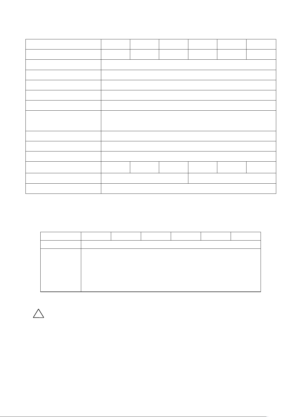
(Maximum static load)(N) *1
value is quoted. (Test repeated 100 times)
!
1. Product Specifications
1-1. Lock unit specification
Lock unit model
Applicable rod size mm *2 Ø12 f8 Ø16 f8 Ø20 f8 Ø20 f8 Ø25 f8 Ø30 f8
Locking operation type Exhaust locking
Fluid Air
Proof pressure 1.5MPa
Max. operating pressure 1.0MPa
MWB∗32-UT MWB∗40-UT MWB∗50-UT MWB∗63-UT MWB∗80-UT MWB∗100-UT
Min. operating pressure
Ambient and fluid temperature
-10℃~70℃ (No freezing)
Operating fluid temperature
Lubrication Not required (non-lube)
Rod speed mm/s
Locking direction Both directions
Holding force
Port size (Rc, NPT, G) 1/8 1/4
Mounting type Basic type, axial foot type, flange type
*1 The holding force (max. static load) shows the maximum capability and does not show the normal holding capability.
Choose the cylinder based on the Selection graph (Page 6 and 7).
*2 Applicable rod size affects holding force. Ensure the rod used is the appropriate size as shown in the table above.
For the shape of the inserted rod, refer to Fig.2 Rod end style.
630 980 1570 2450 3920 6080
0.3MPa
~1000
1-2. Stop accuracy
Lock unit model MWB*32 MWB*40 MWB*50 MWB*63 MWB*80 MWB*100
Stop accuracy ±1.0mm
・Mounting orientation ・・・ Horizontal
・Supply pressure ・・・ 0.5MPa
Conditions
(Used with
air cylinder)
・Piston speed ・・・ 300mm/s
・Load condition ・・・ Upper limit of allowable value
Solenoid valve for lock Mounted to the lock release port
Value shown is based on testing and the largest
Warning
・Confirm the specifications.
This product is desig ned only for use in compress ed air systems including vacuum . Do not operate at
pressures or temperatures outside of the s pecification, as this c ould c a us e damage or malfunction (R ef er
to the specifications.)
Please contact SMC if using fluids other than compressed air (including vacuum) generated by air
compressor.
SMC does not guarantee against any damage if the product is used outside of the specification range.
- 5 -
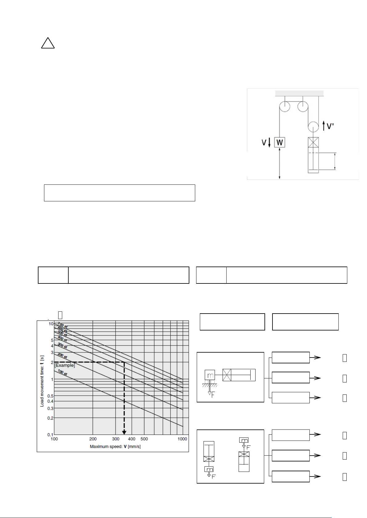
1-3.Precautions on model selection
!
Fig. 1 Double speed mechanism
Step 1: Based on Graph 1
Load applied perpendicularly to the rod
0.3MPa~
0.4MPa~
0.5MPa~
Graph 2
Load applied in extending direction of the rod
0.3MPa~
0.4MPa~
0.5MPa~
Movement
Cylinder
Caution
① Choose the optimum lock unit size based on the operating condition in the application , such as load , travel
distance (stroke) , stroke time , mounting orientation , operating pressure, etc.
② Attention should be taken so that the operating speed does not exceed the maximum speed for the
cylinder.
③ Stroke time means the time taken for the load to move from the start
of the stroke to the end without an intermediate stop.
④ When the cylinder stroke and travel distance of the load are different
such as in double speed mechanism shown as anexample in Fig. 1
, select the model based on the travel distance of the load.
⑤ The example and method of selection below are based on the use of
an intermediate stop including emergency stops during operation.
The maximum load weight for the lock should on l y be used,
when kinetic energy is not generated during lock ing, i. e. for
preventing a static object from falling. Choose the actuator model
based on the operating pressure referring to the Graphs 5 to 7
so that the load mass does not exceed the load for the maximum
speed V = 100mm/s.
distance
of load
Example
【Used with air cylinder】
・Load weight: m=50kg
・Travel distance: st=500mm
・Positioning time: t=2s
・Load: Vertically downwards
・Operating pressure: P=0.4MPa
Step 1 Calculate the maximum speed of the load: V
Calculate the maximum speed of the load, V (mm)
from travel time of the load, t (s) and stroke, st (mm).
Calculate the maximum speed of the load.
∴Max speed V≒350mm/s
Step 2: Select Graph 6 based on the load conditions and
operating pressure. According to the max . speed,
V≒350mm/s calculated above and load weight m=50kG,
∴ø63, which means the bore size of MWB shall be
larger than ø63.
Step 2 Find the lock unit size
Select the appropriate Graph based on the load conditions
and operating pressure. Find the intersection of the load
weight and max. speed from Step 1 . A suitable lock unit
Graph 1
Load Operating pressure
stroke
(Received by guide)
Load applied in retracting direction of the rod
- 6 -
Graph 3
Graph 4
Graph 5
Graph 6
Graph 7
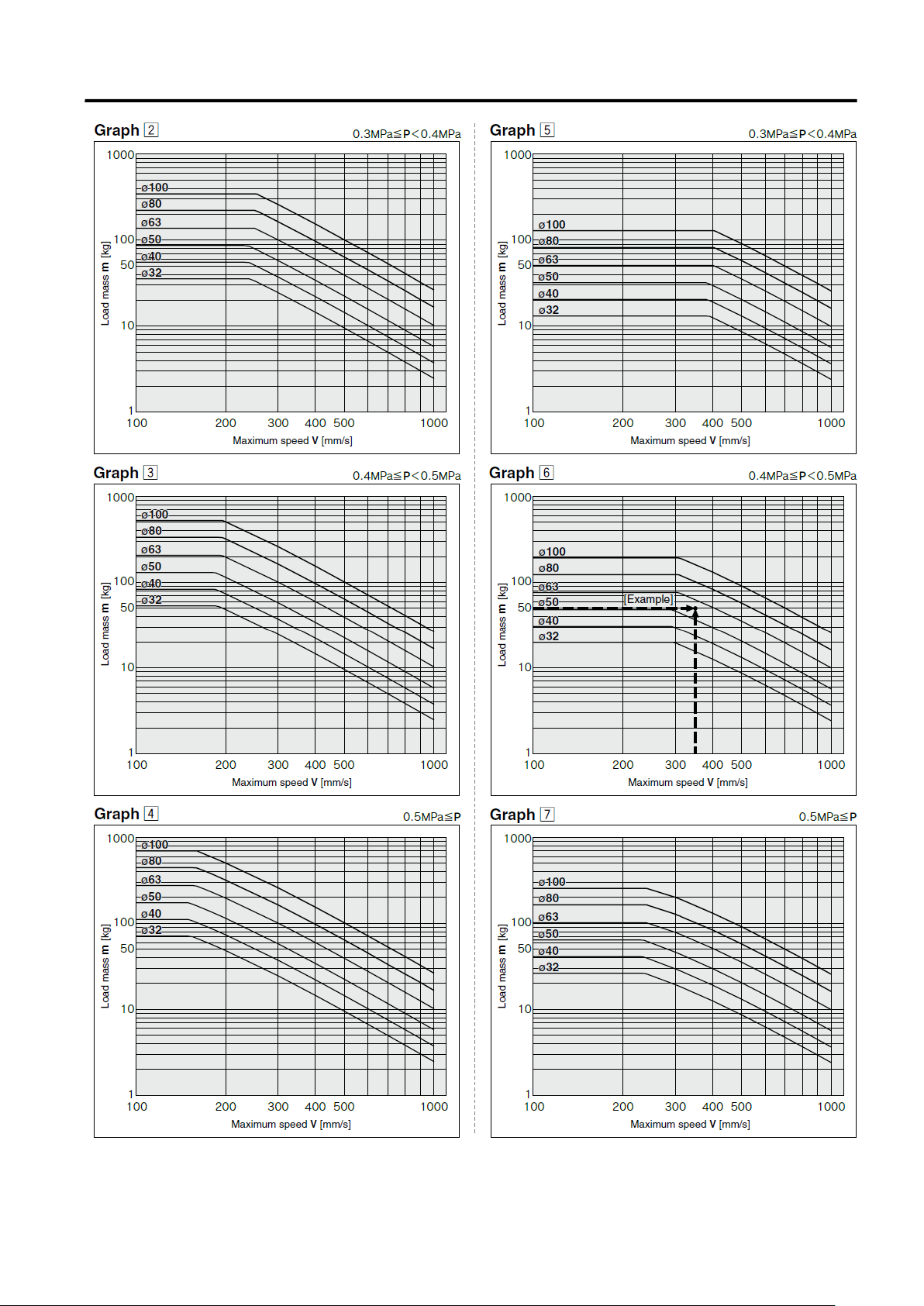
Selection graph
- 7 -

!
!
2. Installation and Handling
2-1. Air supply
① The air supplied to the lock unit should be filtered by SMC AF series air filter and regulated to the specified
set pressure by SMC AR series regulator.
Warning
・Type of fluids
Please contact SMC when using the prod uc t in applications other than with compressed air.
・When there is a large amount of condensate
Compressed air containing a large amount of condensate can cause the malfunction of pneumatic
equipment. An air dryer or water droplet separator should be installed upstream from the filters.
・Drain flushing
If condensate in the drain bowl is not emptied on a regular basis, the bowl will overflow and this may cause
the malfunction of pneumatic equipment. If the drain bowl is difficult to check and remove, installation of a
drain bowl with an auto drain option is recommended.
・Use clean air.
Do not use compr essed air which c ontains chem icals, synthet ic oils contai ning organic s olvents, salts or
corrosive gases, etc., as this can cause damage or a malfunction.
Caution
・When extremely dry air is used as the fluid, degradation of the lubrication properties inside the
equipment may occur, resulting in reduced reliability (or reduced service life) of the equipment.
Please consult with SMC.
・Install an air filter.
Install an air filter upstream near the valve. Select an air filter with a filtration size of 5μm or smaller.
・Therefore, take appropriate measures to ensure air quality, by providing an after cooler, or water
separator, if needed.
Compressed air that contains excessive foreign material may cause malfunction of valves and other
pneumatic equipment. Therefore, take appropriate measures to ensure air quality, such as by providing an
after cooler, air dryer, or water separat or .
・Ensure that the fluid temperature and ambient temperature are within the specified range.
When operating at tem peratures below 5
seals or a malfunction. Corrective measures should be taken to prevent freezing.
② Lubrication of lock unit
The product has been lubricated during manufacturing, so it does not require lubrication in service.
Regular or continuous application of oil to the lock unit may reduce locking force.
For detailed information regarding the quality of the compressed air described above, refer to SMC's
"Air Cleaning Systems".
o
C, moisture in the circ uit may freeze and cause breakage of
- 8 -
 Loading...