

Page 1
IN20267
PRODUCT NAME
Ethernet MPC – Ethernet/IP
MODEL / Series / Product Number
Multi Position Cylinder
MPCXX-XXX-XXX-XX-DUT01607
MPC
TM
- 1 -
Page 2

IN20267
- 2 -
Page 3

IN20267
Table of Contents 1.
Table of Contents .................................................................................................................................... - 3 - 1.
Safety Instructions ................................................................................................................................. - 5 - 2.
About this Manual ............................................................................................................................... - 10 - 3.
MPC ....................................................................................................................................................... - 10 - 3.1.
Purpose ............................................................................................................................................... - 10 - 3.2.
Terminology .......................................................................................................................................... - 11 - 4.
Product Summary ............................................................................................................................... - 12 - 5.
How to Order ......................................................................................................................................... - 13 - 6.
Accessories ........................................................................................................................................ - 13 - 6.1.
Seal cap ............................................................................................................................................... - 14 - 6.2.
Summary of Product Elements ...................................................................................................... - 15 - 7.
Quick Start .............................................................................................................................................. - 16 - 8.
Pneumatics ........................................................................................................................................ - 16 - 8.1.
Supply Pressure .............................................................................................................................. - 16 - 8.2.
Power ................................................................................................................................................... - 17 - 8.3.
Network Cable ................................................................................................................................. - 17 - 8.4.
Ethernet/IP (From PLC Perspective) ..................................................................................... - 18 - 8.5.
IP Address .......................................................................................................................................... - 18 - 8.6.
MPC Default Parameters .................................................................................................................. - 19 - 9.
Ethernet/IP Network Parameters ................................................................................................ - 19 - 10.
Network Specifications ................................................................................................................ - 19 - 10.1.
DLR (Device Level Ring) .............................................................................................................. - 19 - 10.2.
Hold on Connection Loss ............................................................................................................. - 19 - 10.3.
Hold Till Connection ...................................................................................................................... - 19 - 10.4.
Quick Connect .................................................................................................................................. - 19 - 10.5.
Daisy Chaining Power and Ethernet ............................................................................................ - 20 - 11.
Connecting MPCs for Daisy Chaining ..................................................................................... - 20 - 11.1.
LED Indication ...................................................................................................................................... - 21 - 12.
Studio 5000 Setup ............................................................................................................................... - 23 - 13.
EDS file – Rockwell Studio 5000............................................................................................... - 23 - 13.1.
Adding a device to Ethernet - Rockwell Studio 5000 ...................................................... - 24 - 13.2.
Setpoint ................................................................................................................................................... - 27 - 14.
Example: Convert the Position to Counts ............................................................................. - 27 - 14.1.
Example: Pseudo Code for 100mm MPC mm ...................................................................... - 27 - 14.2.
Ladder Logic Example .................................................................................................................. - 27 - 14.3.
LabVIEW Example .......................................................................................................................... - 28 - 14.4.
Web Pages .............................................................................................................................................. - 29 - 15.
System Page ...................................................................................................................................... - 29 - 15.1.
Diagnostics Page ............................................................................................................................. - 30 - 15.2.
IO Data Page ...................................................................................................................................... - 31 - 15.3.
Version Page ..................................................................................................................................... - 32 - 15.4.
Ethernet MPC Status Page ........................................................................................................... - 33 - 15.5.
Login Page ......................................................................................................................................... - 34 - 15.6.
Contact Page ..................................................................................................................................... - 35 - 15.7.
MPC Configuration Page .............................................................................................................. - 36 - 15.8.
Network Page ................................................................................................................................... - 38 - 15.9.
Explicit Messaging ............................................................................................................................... - 41 - 16.
Installation and Handling ................................................................................................................. - 42 - 17.
Air supply ........................................................................................................................................... - 42 - 17.1.
- 3 -
Page 4

IN20267
Operating environment................................................................................................................ - 42 - 17.2.
Do not use the product in a food zone: .................................................................................. - 42 - 17.3.
OK to use the product in: ............................................................................................................. - 42 - 17.4.
Non-food zone - An environment in which foods do not contact the cylinder: .... - 42 - 17.5.
Do not use in an area where surges are generated: ......................................................... - 42 - 17.6.
Installation ........................................................................................................................................ - 43 - 17.7.
Wiring (Including connecting/disconnecting of the connectors) .............................. - 44 - 17.8.
Adjustment and Operation ......................................................................................................... - 46 - 17.9.
Washing ................................................................................................................................................... - 47 - 18.
Maintenance .......................................................................................................................................... - 48 - 19.
Recovering the IP Address of SMC Ethernet MPC .................................................................. - 49 - 20.
- 4 -
Page 5
Caution :
CAUTION indicates a hazard with a low level of risk which, if not
avoided, could result in minor or moderate injury.
Warning:
WARNING indicates a hazard with a medium level of risk which,
if not avoided, could result in death or serious injury.
Danger :
DANGER indicates a hazard with a high level of risk which, if not
avoided, will result in death or serious injury.
Warning
1. The compatibility of the product is the responsibility of the person who designs the
equipment or decides its specifications.
Since the product specified here is used under various operating conditions, its compatibility with specific
equipment must be decided by the person who designs the equipment or decides its specifications
based on necessary analysis and test results. The expected performance and safety assurance of the
equipment will be the responsibility of the person who has determined its compatibility with the product.
This person should also continuously review all specifications of the product referring to its latest catalog
information, with a view to giving due consideration to any possibility of equipment failure when
configuring the equipment.
2. Only personnel with appropriate training should operate machinery and equipment.
The product specified here may become unsafe if handled incorrectly. The assembly, operation and
maintenance of machines or equipment including our products must be performed by an operator who is
appropriately trained and experienced.
3. Do not service or attempt to remove product and machinery/equipment until safety is
confirmed.
1. The inspection and maintenance of machinery/equipment should only be performed after measures to
prevent falling or runaway of the driven objects have been confirmed.
2. When the product is to be removed, confirm that the safety measures as mentioned above are
implemented and the power from any appropriate source is cut, and read and understand the specific
product precautions of all relevant products carefully.
3. Before machinery/equipment is restarted, take measures to prevent unexpected operation and
malfunction.
4. Contact SMC beforehand and take special consideration of safety measures if the
product is to be used in any of the following conditions.
1. Conditions and environments outside of the given specifications, or use outdoors or in a place exposed to
direct sunlight.
2. Installation on equipment in conjunction with atomic energy, railways, air navigation, space, shipping,
vehicles, military, medical treatment, combustion and recreation, or equipment in contact with food and
beverages, emergency stop circuits, clutch and brake circuits in press applications, safety equipment or other
applications unsuitable for the standard specifications described in the product catalog.
3. An application which could have negative effects on people, property, or animals requiring special
safety analysis.
4. Use in an interlock circuit, which requires the provision of double interlock for possible failure by using
a mechanical protective function, and periodical checks to confirm proper operation.
Safety Instructions 2.
These safety instructions are intended to prevent hazardous situations and/or equipment damage.
These instructions indicate the level of potential hazard with the labels of "Caution", "Warning" or
"Danger". They are all important notes for safety and must be followed in addition to International
standards (ISO/IEC), and other safety regulations.
ISO 4414: Pneumatic fluid power -- General rules relating to systems.
ISO 4413: Hydraulic fluid power -- General rules relating to systems.
IEC 60204-1: Safety of machinery -- Electrical equipment of machines. (Part 1: General requirements)
ISO 10218-1992: Manipulating industrial robots -- Safety.
Etc.
IN20267
- 5 -
Page 6

IN20267
Caution
The product is provided for use in manufacturing industries.
The product herein described is basically provided for peaceful use in manufacturing
industries.
If considering using the product in other industries consult SMC beforehand and
exchange specifications or a contract if necessary.
If anything is unclear, contact your nearest sales branch.
1. The warranty period of the product is 1 year in service or 1.5 years after the product is
delivered.
*1)
Also, the product may have specified durability, running distance or replacement parts.
Please consult your nearest sales branch.
2. For any failure or damage reported within the warranty period which is clearly our
responsibility, a replacement product or necessary parts will be provided.
This limited warranty applies only to our product independently, and not to any other damage
incurred due to the failure of the product.
3. Prior to using SMC products, please read and understand the warranty terms and
disclaimers noted in the specified catalog for the particular products.
*1) Vacuum pads are excluded from this 1 year warranty.
A vacuum pad is a consumable part, so it is warranted for a year after it is delivered.
Also, even within the warranty period, the wear of a product due to the use of the vacuum pad or failure due
to the deterioration of rubber material are not covered by the limited warranty.
When the product is exported, strictly follow the laws required by the Ministry of Economy, Trade
and Industry (Foreign Exchange and Foreign Trade Control Law).
This operation manual has been written for those who have knowledge of machinery and
apparatus that use pneumatic equipment and have full knowledge of assembly, operation
and maintenance of such equipment.
Please read this operation manual carefully and understand it before assembling,
operating or providing maintenance to the product.
Limited warranty and Disclaimer/Compliance Requirements
The product used is subject to the following "Limited warranty and Disclaimer" and "Compliance
Requirements".
Read and accept them before using the product.
Limited warranty and Disclaimer
Compliance Requirements
Operator
- 6 -
Page 7
Warning
■Do not disassemble, modify (including changing the printed circuit board) or repair.
An injury or failure can result.
■Do not operate the product outside of the specifications.
Do not use for flammable or harmful fluids.
Fire, malfunction, or damage to the product can result.
Verify the specifications before use.
■Do not operate in an atmosphere containing flammable or explosive gases.
Fire or an explosion can result.
This product is not designed to be explosion proof.
■If using the product in an interlocking circuit:
Provide a double interlocking system, for example a mechanical system.
Check the product regularly for proper operation.
Otherwise malfunction can result, causing an accident.
■The following instructions must be followed during maintenance:
Turn off the power supply.
Stop the air supply, exhaust the residual pressure and verify that the air is released
before performing maintenance.
Otherwise an injury can result.
Caution
■After maintenance is complete, perform appropriate functional inspections.
Stop operation if the equipment does not function properly.
Safety cannot be assured in the case of unexpected malfunction.
■Provide grounding to assure the safety and noise resistance of the Serial System.
Individual grounding should be provided close to the product with a short cable.
■Precautions
IN20267
- 7 -
Page 8

■NOTE
○Follow the instructions given below when designing, selecting and handling the product.
The instructions on design and selection (installation, wiring, environment, adjustment, operation,
maintenance, etc.) described below must also be followed.
Product specifications
When conformity to UL is necessary the SI unit must be used with a UL1310 Class2 power supply.
The SI unit is a approved product only if they have a mark on the body.
Use the specified voltage.
Otherwise failure or malfunction can result.
Reserve a space for maintenance.
Allow sufficient space for maintenance when designing the system.
Do not remove any nameplates or labels.
This can lead to incorrect maintenance, or misreading of the operation manual, which could cause
damage or malfunction to the product.
It may also result in non-conformity to safety standards.
Product handling
Installation
Do not drop, hit or apply excessive shock to the Ethernet ITV system.
Otherwise damage to the product can result, causing malfunction.
Tighten to the specified tightening torque.
If the tightening torque is exceeded the mounting screws may be broken.
IP65 protection cannot be guaranteed if the screws are not tightened to the specified torque.
Never mount a product in a location that will be used as a foothold.
The product may be damaged if excessive force is applied by stepping or climbing onto it.
Wiring
Avoid repeatedly bending or stretching the cables, or placing heavy load on them.
Repetitive bending stress or tensile stress can cause breakage of the cable.
Wire correctly.
Incorrect wiring can break the product.
Do not perform wiring while the power is on.
Otherwise damage to the fieldbus system and/or I/O device can result, causing malfunction.
Do not route wires and cables together with power or high voltage cables.
Otherwise the fieldbus system and/or I/O device can malfunction due to interference of noise and surge
voltage from power and high voltage cables to the signal line.
Route the wires (piping) of the fieldbus system and/or I/O device separately from power or high voltage
cables.
Confirm proper insulation of wiring.
Poor insulation (interference from another circuit, poor insulation between terminals, etc.) can lead to
excess voltage or current being applied to the product, causing damage.
Take appropriate measures against noise, such as using a noise filter, when the fieldbus system is
incorporated into equipment.
Otherwise noise can cause malfunction.
IN20267
- 8 -
Page 9

IN20267
Environment
Select the proper type of protection according to the operating environment.
IP65 protection is achieved when the following conditions are met.
(1) The units are connected properly with fieldbus cable with M12 connector and power cable with M12
connector.
(2) Suitable mounting of each unit (if using the optional manifold mount).
(3) All unused connectors are closed with a properly installed seal cap.
If using in an environment that is exposed to water splashes, please take measures such as using a
cover.
Do not use in a place where the product could be splashed by oil or chemicals.
If the product is to be used in an environment containing oils or chemicals such as coolant or cleaning
solvent, even for a short time, it may be adversely affected (damage, malfunction etc.).
Do not use the product in an environment where corrosive gases or fluids could be splashed.
Otherwise damage to the product and malfunction can result.
Do not use in an area where surges are generated.
If there is equipment which generates a large amount of surge (solenoid type lifter, high frequency
induction furnace, motor, etc.) close to the fieldbus system, this may cause deterioration or breakage of
the internal circuit of the fieldbus system. Avoid sources of surge generation and crossed lines.
When a surge-generating load such as a relay or solenoid is driven directly, use a fieldbus system with a
built-in surge absorbing element.
Direct drive of a load generating surge voltage can damage the fieldbus system.
The product is NOT immune to lightning strikes. Take measures against lightning strikes in the system.
Prevent foreign matter such as remnant of wires from entering the fieldbus system to avoid failure and
malfunction.
Mount the product in a place that is not exposed to vibration or impact.
Failure or malfunction can result.
Do not expose the product to direct sunlight.
If using in a location directly exposed to sunlight, shade the product from the sunlight. Failure or
malfunction can result.
Keep within the specified operating temperature range.
Malfunction can result.
Do not operate close to a heat source, or in a location exposed to radiant heat.
Malfunction can result.
Adjustment and Operation
Perform settings suitable for the operating conditions.
Incorrect setting can cause operation failure.
Please refer to the PLC manufacturer's manual etc. for details of programming and addresses.
For the PLC protocol and programming refer to the relevant manufacturer's documentation.
Maintenance
Turn off the power supply, stop the supplied air, exhaust the residual pressure and verify the release of
air before performing maintenance.
There is a risk of unexpected malfunction.
Perform regular maintenance and inspections.
There is a risk of unexpected malfunction.
After maintenance is complete, perform appropriate functional inspections.
Stop operation if the equipment does not function properly.
Otherwise safety is not assured due to an unexpected malfunction or incorrect operation.
Do not use solvents such as benzene, thinner etc. to clean the unit.
They could damage the surface of the body and erase the markings on the body. Use a soft cloth to
remove stains. For heavy stains, use a cloth soaked with diluted neutral detergent and fully squeezed,
then wipe up the stains again with a dry cloth.
- 9 -
Page 10

About this Manual 3.
MPC
3.1.
The MPC is SMC's low cost Ethernet positioning cylinder. The MPC series offers a cylinder, solenoid
valve, linear positioner, and controller in one package. With its integral position control, the MPC
needs only power and Ethernet input signal. The target position is kept by opening and closing
solenoid valves controlling pressure on the cylinder. The MPC has an output signal to give position
feedback to a customer's controller. Standard ball bushings protect against side load.
Purpose 3.2.
The purpose of this manual is to provide the user with necessary information to install, configure,
and use the MPCXX-XXX-XXX-XX-DUT01607. The MPC may be operated under the control of a
network connected PLC. This manual provides information for MPC setup and configuration,
examples of the web interface, and a brief overview of the PLC. This document is not an operator’s
manual for the Rockwell PLC or any other PLC. Please see the PLC manufacturer’s documentation
for detailed instructions on the setup and use of your PLC.
IN20267
- 10 -
Page 11

IN20267
Terms
Meaning
100
100BASE-TX
Standard LAN transmission line with communication speed of 100 Mbps.
A
Auto negotiation
The function that automatically optimizes the common communication parameters
such as speed, duplex mode, and flow control between Ethernet devices.
C
Counts
The MPC controls and reports position internally in Counts. The counts are used by
hardware devices to control and measure the position regulated by the MPC.
Current consumption
The current (power) necessary to operate each unit or device.
D
Downstream
Devices receiving power or communications signals which originate from or are
passed through a given device are downstream of that device.
DLR
An abbreviation for Device Level Ring: Performs a fast switching of the communication
route when any problem occurs with the Ring network to maintain communication.
E
Enclosure (IPxy)
Abbreviation of International (Ingress) Protection. A standard related to protection from
external objects (hands, steel balls, steel wire, dust, water, etc.) applied to the product.
F
Fieldbus
The protocol that uses digital communication to exchange signals between field
equipment (instruments and actuators).
Full duplex
Communication system that can send and receive data at the same time bidirectionally (similar to standard telephone).
H
Half duplex
Communication system that sends and receives data in one direction at a time (similar
to two-way radio).
I
IP address
A 32 bit digit sequence which is assigned to identify devices which are connected to
the network. This address must be unique for each device to ensure proper operation
of the network.
M
MAC address
A unique number inherent to all devices which are connected to Ethernet.
Ethernet/IP
By combining Ethernet, CANopen and hard real-time capabilities, Ethernet/IP
integrates features and abilities from three different worlds. In contrast to a number of
competing products, Ethernet/IP has remained extremely close to the Ethernet
standard, retaining original Ethernet features and so reducing the cost of deployment
in industrial environments. The protocol's second major advantage is the integration of
CANopen technology, a robust and proven protocol widely used throughout the field of
automation whose extensive standardization greatly simplifies network configuration.
P
PC
Personal Computer.
PLC
Abbreviation for Programmable Logic Controller. A digital computer/controller used for
automation of electromechanical processes.
R
Reboot
Unless otherwise noted, the term “reboot” in this document means that the MPC must
be power cycled.
S
Setpoint
The specified position which the MPC has been directed to maintain. Setpoint may be
specified via a setpoint sent from a PLC. Setpoint may refer to a human readable
value – including measurement units – used to specify the position to be maintained
by the MPC. Physical setpoint is a unit-less value (physical counts) used internally
to control and monitors the MPC’s physical position. Unless noted, setpoint refers to
the human readable value including measurement units. Setpoint and position status
values are sent between the MPC and a PLC in counts (physical setpoint).
Serial Interface (SI)
A communication interface between two digital systems that transmits data as a series
of voltage pulses down a wire. Each pulse represents a single bit of data.
SI unit
Abbreviation for Serial Interface unit. A unit connected to a PLC to communicate input
and output data. The MPC connection to another MPC or to a PLC or PC is a Serial
Interface (SI).
T
Topology
Connection configuration of the network.
U
Upstream
A device which provides power or communications signals to a given device is
upstream of that device.
Terminology 4.
Table 4-1 - Definitions and Terminology
- 11 -
Page 12

Product Summary 5.
The MPCXX-XXX-XXX-XX-DUT01607 (MPC) is a multi-position cylinder which is controlled by an
Ethernet interface. MPCs move to a position value specified by the user. In the past, an electric
actuator was the only option for applications demanding a multiple number of stroke positions.
SMC's MPC series now provides an alternative and economical solution.
The Ethernet interface allows a user to configure, control, and monitor the MPC over a
communication link using commands sent from a PLC or internal webserver. The user can change
the position setpoint as required. The user can also monitor the operation of the MPC, verifying the
actual position.
Offered as a pneumatic and lower cost alternative, the MPC (Multi Position Cylinder) uses an
Ethernet input signal to automatically adjust the actuator stroke. Once the MPC reaches the desired
position, it is pneumatically locked until the input signal is changed.
To accomplish this, the MPC utilizes an integrated cylinder, solenoid valve, linear sensor, and
controller all in one unit. You need only to supply air, power, and the appropriate input signal. This
easy adjustment makes the MPC perfect for on the fly changes to your process.
IN20267
- 12 -
Page 13
How to Order6.
MPC unit
connection
Description
Compatible cable
Part number
Length
Specifications
Fieldbus
interface
Cables
EX9-AC010ENPSRJ
1m
One end: molded M12 straight connector. Other end:
RJ45 connector (Ethernet).
EX9-AC020ENPSRJ
2m
EX9-AC030ENPSRJ
3m
EX9-AC050ENPSRJ
5m
EX9-AC100ENPSRJ
10m
PCA-1446566
5m
One end: molded M12 right angle connector. Other end:
flying leads.
EX9-AC005ENM12M12
0.5m
Both ends: molded M12 straight connectors.
EX9-AC050EN-
M12M12
5m
Field wireable
Connector
PCA-1446553
--
Connector: M12 straight plug connector. Use with PCA1446566 to make a cable of desired length.
Power
supply
Cables
EX500-AP010-SE
1m
One end: molded M12 straight connector. Other end:
flying leads.
EX500-AP050-S
5m
EX500-AP010-A
1m
One end: molded M12 right angle connector. Other end:
flying leads.
EX500-AP050-A
5m
Cable with
Speedcon
connector
PCA-1401804
1.5m
One end: molded M12 straight connector. Other end:
flying leads.
PCA-1401805
3m
PCA-1401806
5m
(Refer to product drawing for latest information)
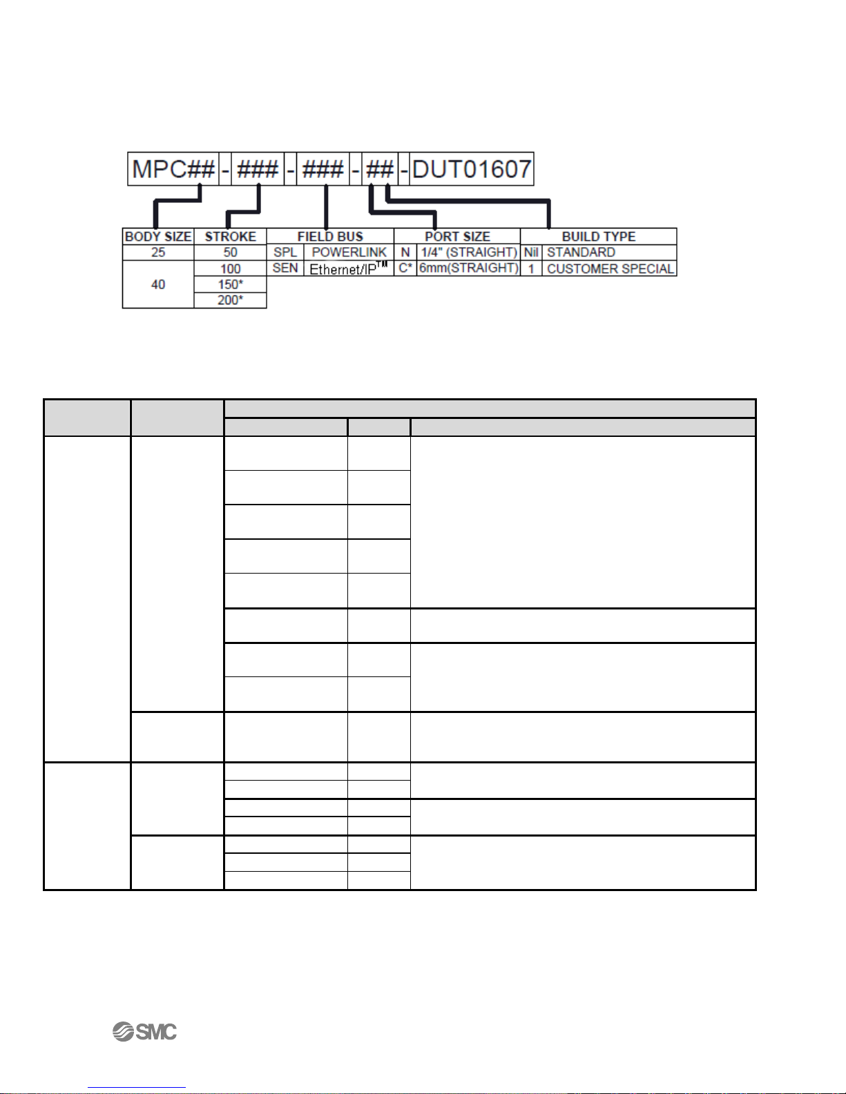
Specify the part number for your MPC. The part number describes the MPC as follows:
Figure 6-1 – MPC Part Numbers
Accessories 6.1.
Connector cables (recommended – not included with MPC)
IN20267
Note: More options are available. Contact SMC for information on these options.
- 13 -
Table 6-2 - Recommended Cables
Page 14
IN20267
Description
Part No.
Specification
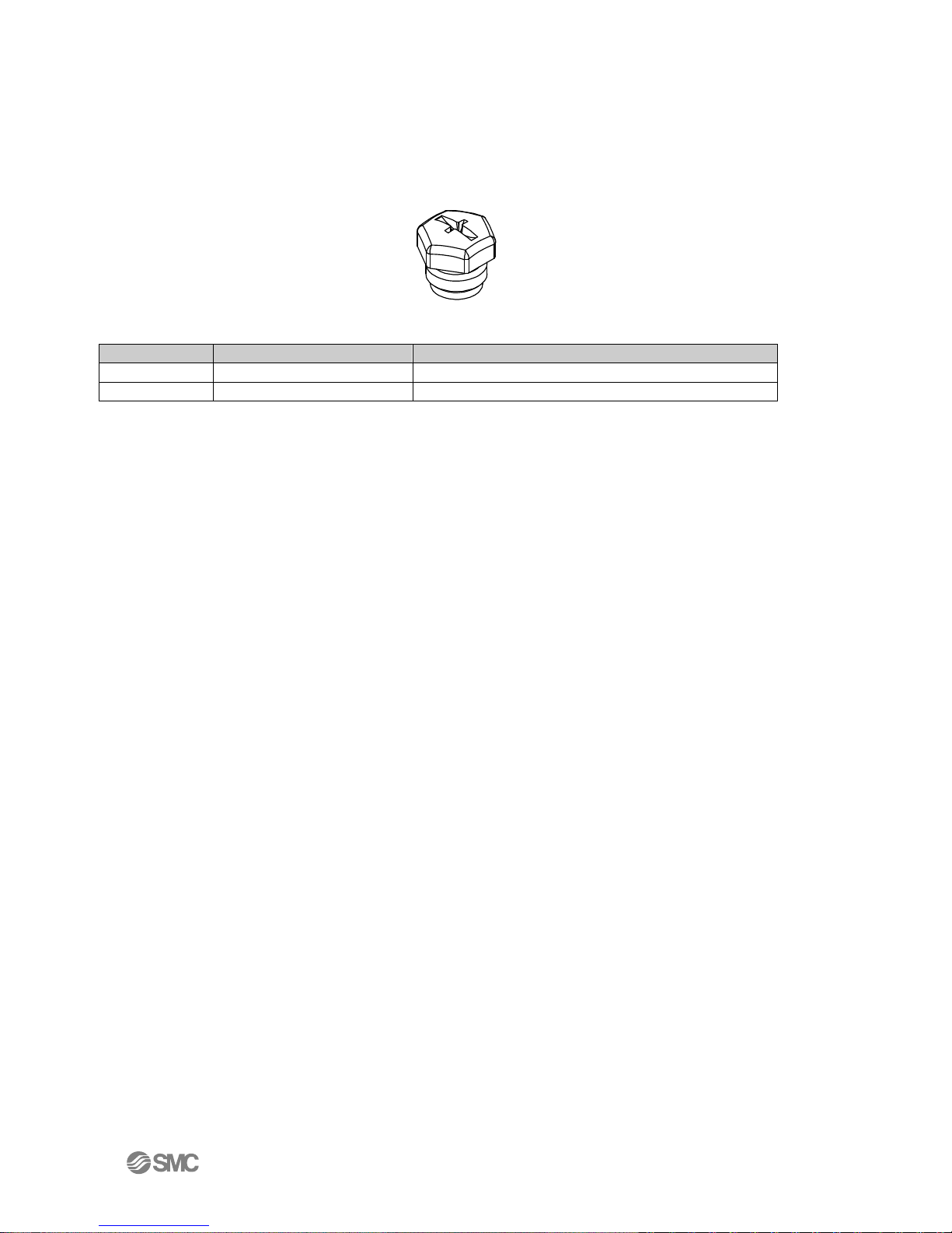
Seal cap
EX9-AWTS
For M12 connector socket: 10pcs.
Seal cap
UIUSP-C08-DUQ00833
For M12 Female Connector 1 pcs.
Seal cap 6.2.
Seal caps are used to protect the M12 size connector openings. It is recommended that seal caps be
used on all unused M12 connector openings. Use of seal caps is required for all unused connections
for IP65 rating. (One Ethernet and one Power seal cap are attached to the MPC when shipped from
factory as shown in figure 6-1.)
Figure 6-3 – Seal Cap
Table 6-4 - Seal Cap Part Numbers
- 14 -
Page 15
IN20267
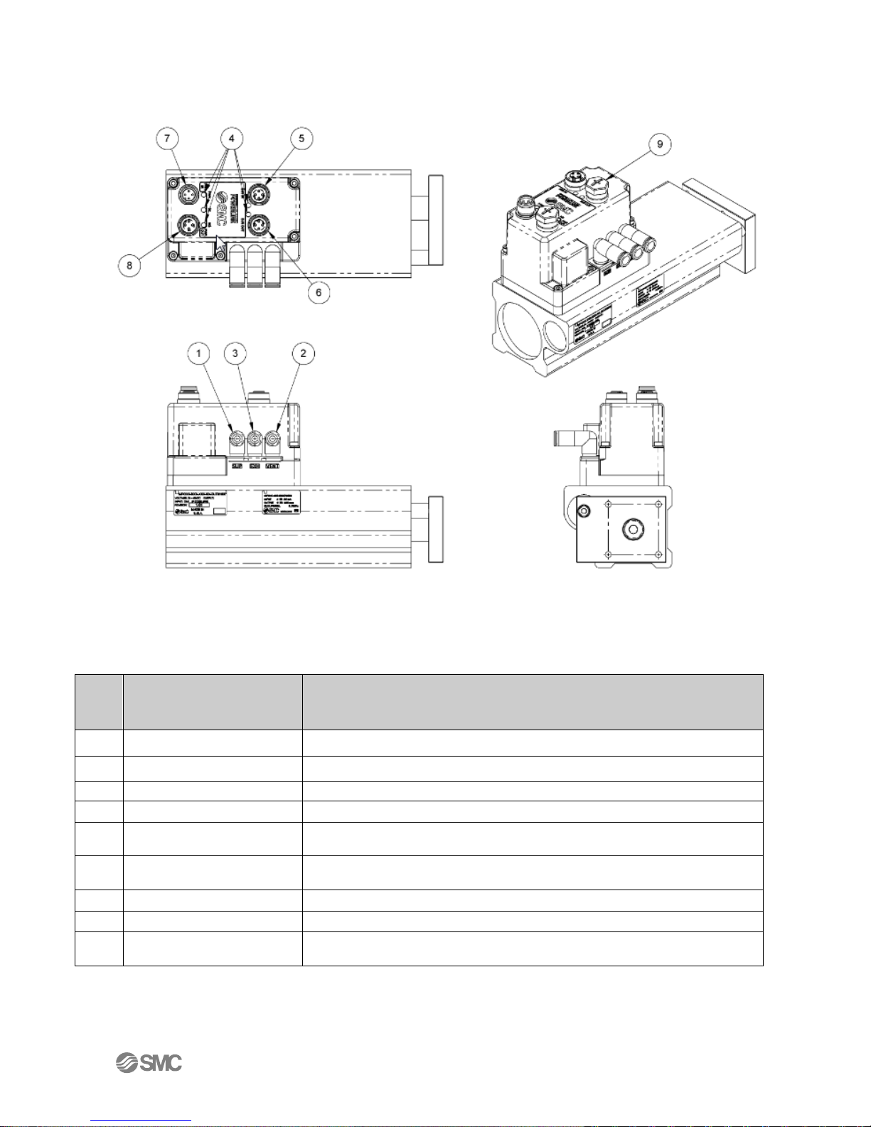
N
o
.
Element
Description
1
Air Supply
CDA supply for cylinder
2
Vent
Cover / Valve Vent
3
Exhaust
Cylinder Exhaust Port
4
LED Display
Status LEDs
5
Fieldbus interface
connector (BUS IN)
Ethernet connection (Female M12, 4-pin socket, D-coded)
6
Fieldbus interface
connector (BUS OUT)
Ethernet connection (Female M12, 4-pin socket, D-coded for daisy chain
operation)
7
Power supply in
Cylinder operating voltage (Male M12 4-pin plug, A-coded connector)
8
Power supply out
Power Daisy chain (Female M12 4-pin socket, A-coded connector)
9
Seal Cap (Accessory)
1pc. seal cap for unused fieldbus interface connector (BUS OUT); 1pc seal
cap for unused power supply out connector
Summary of Product Elements 7.
Figure 7-1 - MPC Product Elements Drawing
Table 7-2 – MPC Products Elements Table
- 15 -
Page 16
IN20267
Caution
DO NOT enable air pressure until ALL pneumatic lines in the circuit have been properly
connected and the connections have been verified to be correct. Failure to follow this
requirement can result in severe injury or equipment damage.
Be SURE you understand the location and function of the ports BEFORE connecting the MPC
to an airline and an application device. VERIFY that these lines are properly connected
BEFORE enabling pneumatic pressure and BEFORE powering the MPC.
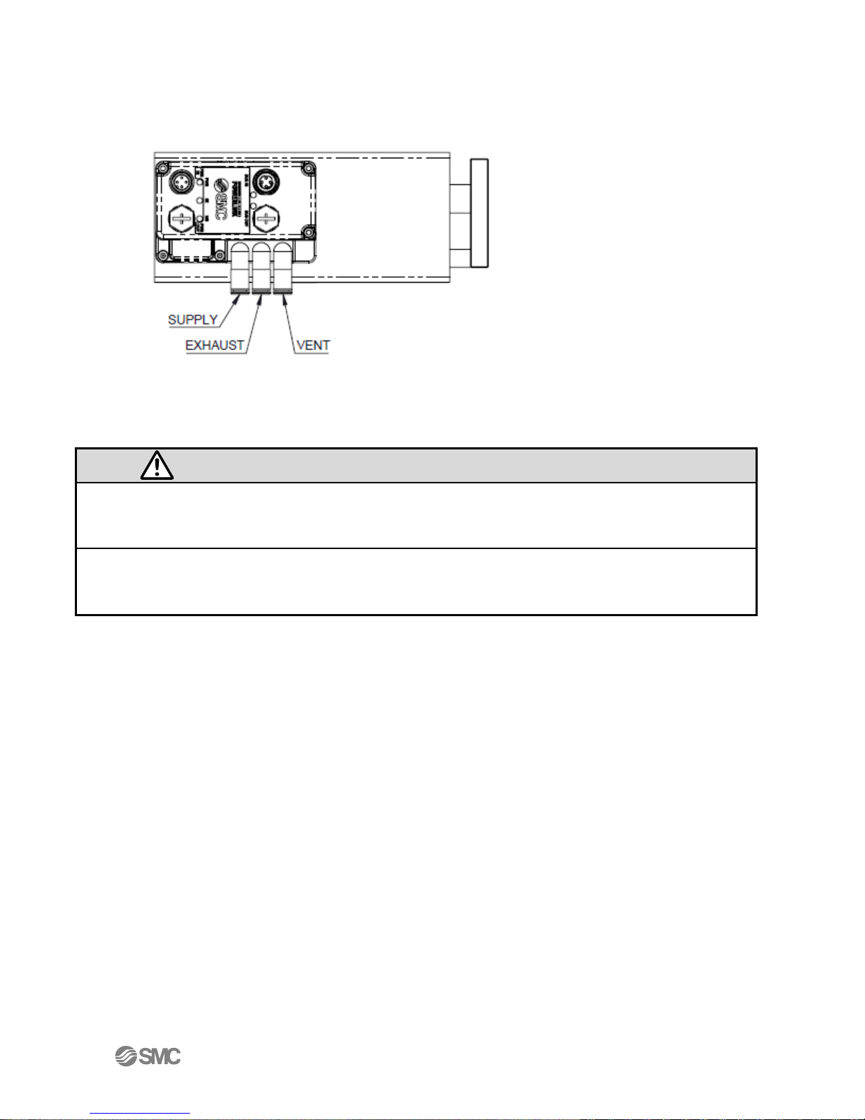
Quick Start 8.
Pneumatics 8.1.
Figure 8-1 – MPC Pneumatics Plumbing
Supply Pressure 8.2.
CDA Supply Pressure is 0.1 to 0.7MPa. 8.2.1.
- 16 -
Page 17

IN20267
No.
Designation
Description
1
TD+
Transmit Data +
2
RD+
Receive Data +
3
TD-
Transmit Data -
4
RD-
Receive Data -
Power 8.3.
Figure 8-2 – MPC Power Cable Pin Connections
Table 8-3 – MPC Power Pinout
Power in is 24 - 48 VDC +- 10% @ ~ 7Watts max 8.3.1.
For more about power refer to Daisy Chaining Power 8.3.2.
Network Cable 8.4.
Network Bus In and Bus Out: M12 4-pin socket D-coded connectors 8.4.1.
The Ethernet MPC Uses a standard M12 industrial Ethernet cable. For cable selection see
Accessories. You may use either port (“BUS IN” or “BUS OUT”) for the Ethernet connection to the
MPC.
- 17 -
Table 8-4 - MPC Ethernet Cable Pin Signals
Page 18

IN20267
TYPE
Instance
Size
Description
Output
100
1 INT or 2 SINT
Position set-point
Input
150
2 INT or 4 SINT
2 bytes measured position, 2 bytes diagnostics
Ethernet/IP (From PLC Perspective) 8.5.
The EDS File can be downloaded from www.smcusa.com
Refer to Studio 5000 Setup for more details on PLC setup
Table 8-5 - IO Data Key
Output Position: 12 bit value that is the position setpoint. 8.5.1.
The 4 most significant bits should be 0.
Input Position: 12 bit value of the current position. 8.5.2.
The 4 most significant bits are 0.
Input Diagnostics: 16 bit value (bits are numbered from the right) 8.5.3.
Bit zero = power OK: 0= OK, 1 = Out of range
IP Address 8.6.
The IP address is set to (192.168.1.20) at the factory. The IP address can be changed using the built
in MPC web server. The webserver can be accessed by a PC connected to the network and set to the
same subnet. DHCP/Bootp can be selected from the webserver if desired. Refer to Web pages for
more details.
- 18 -
Page 19

IN20267
Description
Value
IP Address
192.168.1.20
Subnet
255.255.0.0
Gateway
0.0.0.0
DNS Server
0.0.0.0
Hold on connection loss
Enabled
Hold till connection established
Enabled
Webpage Login ID
“user”
Webpage Login Password
“user”
MPC Default Parameters 9.
The default values of configuration parameters are given below. The user can change these
parameters, if needed, as part of the MPC setup process. Refer to Web pages for more details.
Refer to Studio 5000 Setup for more details on PLC setup.
Table 9-1 – Default Parameters
Ethernet/IP Network Parameters 10.
Network Specifications 10.1.
Two M12 Ethernet Ports 10.1.1.
Built in Ethernet switch 10.1.2.
Minimum cycle time (RPI) 4ms 10.1.3.
DLR (Device Level Ring) 10.2.
Ethernet MPC is capable of being configured into a DLR network 10.2.1.
Hold on Connection Loss 10.3.
MPC will hold last position communicated by the PLC. The Ethernet MPC will 10.3.1.
continue to maintain this position as long as power and air are still supplied.
Hold Till Connection 10.4.
MPC will hold its last position until a connection to PLC is established. The PLC 10.4.1.
should be ready to communicate the correct position upon connection to the
Ethernet MPC. The webserver or explicit messages can all be used to generate this
initial connection. This location is maintained by closed valves. Some drifting of
position could occur over time as air leaks from the cylinder.
Quick Connect 10.5.
The Ethernet MPC has Quick Connect functionality. 10.5.1.
- 19 -
Page 20

IN20267
Daisy Chaining Power and Ethernet 11.
The daisy chaining feature is an optional way to power MPC units. This eliminates the need to run a
power cable to each MPC from the power supply directly or running a separate power trunk line.
Daisy chaining can eliminates the need for long power cables.
Connecting MPCs for Daisy Chaining 11.1.
The cable connections are critical for proper operation of daisy chaining. The following is an
example of proper cable connections.
When daisy chaining, the first MPC can supply power to the next 19 MPCs without the need for
another power supply if using 48 volts. This drops to only 4 if using 24 volts. The MPC has under
voltage detection to let you know if you do not have enough voltage supplied to the MPC for proper
operation. The MPC does not limit the number of MPCs which can be connected to an Ethernet
network. The network size limits come from the PLC and how many devices it can talk to at one
time.
Figure 11-1 - MPC Group Power Connections
The diagram illustrates the Ethernet communication and power cable connections required to
support 21 MPCs when daisy chaining is in use. The MPCs in the dashed box form a single Power
daisy chain group. Note that power daisy chaining supports a maximum of 20 MPCs in one power
group. This does not mean that you cannot have more than 20 MPCs connected to a single supply.
More MPCs can be supported as long as the supply can source enough power to support multiple
chains of MPCs. Each MPC uses about 7 watts of power when moving.
The following rules must be followed for proper operation
Good quality power and Ethernet cables must be used when daisy chaining 11.1.1.
No more than 4 amps per connector pair should be placed across MPC power In to 11.1.2.
Power Out. This is a total of 8 amps if using both connector pairs as is suggested
when using daisy chaining to reduce line and connector voltage loss.
- 20 -
Page 21

IN20267
Balloon Number
Name
Description
1
PWR
Power OK indicator
2
NS
Network Status
3
MS
Module Status
4
Link/ACT
Bus In Ethernet Link and Activity Status
5
Link/ACT
Bus Out Ethernet Link and Activity Status
LED Indication 12.
Figure 12-1 MPC LED Locations
Table 12-2 MPC LED Indentifcation
- 21 -
Page 22

LED
LED Status
Description
PWR
Green ON
Voltage for the MPC is supplied.
OFF
Voltage for the MPC is not supplied or is outside the
tolerance range (24 VDC -10%)
NS
OFF
The MPC operating voltage is not supplied or the
MPC is in DHCP mode without a valid IP address.
Green ON
Communication established.
Green flashing
Idle link.
Red flashing
Communication time out.
Red ON
IP address duplicated.
MS
OFF
The MPC operating voltage is not supplied.
Green ON
Operating normally – communication in progress.
Green flashing
Operating normally – idle link.
Red flashing
Recoverable error – Possible low voltage.
Red ON
Unrecoverable error.
-
IN20267
Table 12-3 MPC LED Status Key
- 22 -
Page 23

Studio 5000 Setup 13.
EDS file – Rockwell Studio 5000
13.1.
The EDS file can be downloaded from the www.smcusa.com website. Install the EDS file by
selecting Tools then EDS Hardware Installation Tool.
IN20267
Figure 13-1 EDS Tool
Continue importing the EDS file by following the prompts then select the EDS file obtained from the
www.smcusa.com website.
- 23 -
Page 24

IN20267
Adding a device to Ethernet - Rockwell Studio 5000 13.2.
Add the Ethernet MPC by right clicking on Ethernet then clicking on New Module 13.2.1.
Figure 13-2 - New Module
Select Module Type - Uncheck the Module Type Vendor Filters then scroll down to 13.2.2.
SMC Corporation vendor and check the box. Select MPC from the list of items then
click on create. You can also use search to find the MPC.
- 24 -
Figure 13-3 – Module Select
Page 25

IN20267
New Module - Fill in the Name you want to give the MPC and the IP address. MPC 13.2.3.
will automatically be added to the name. Description is optional. Now select
Change…
Figure 13-4 – New ModuleSettings
Module Definition - Click on SINT and then select INT. Switching to INT makes 13.2.4.
using the Ethernet MPC easier. Click on OK and then OK again
Figure 13-5 – Module Connections
- 25 -
Page 26

IN20267
Ethernet - You now have an Ethernet MPC added to your Ethernet network 13.2.5.
Figure 13-6 – PLC Ethernet
MPC Tags will show up in the Controller Tags under the name you gave the MPC 13.2.6.
above
Figure 13-7 – PLC Input and Output Data for the Ethernet MPC
- 26 -
Page 27

Position
Body Type
mm
Counts / mm
inches
Counts / inch
%fs
Counts / %
50mm
81.90
2080.26
40.95
100mm
40.95
1040.13
40.95
150mm
27.30
693.42
40.95
200mm
20.48
520.07
40.95
Setpoint 14.
Users specifying the Setpoint (position) using a PLC need to be aware that the PLC and Ethernet
MPC use counts (see Terminology) to represent the position setpoint (from the PLC) and the
current position value (from the MPC). These values are displayed as 16-bit hexadecimal
quantities. (The 4 MSB should always be 0).
If the PLC allows a user to enter the position in units, for example, millimeters, it is the
responsibility of the PLC program to convert the position in millimeters to the appropriate count
value. It is also the responsibility of the PLC program to convert the position return value (current
position) from counts to millimeters as needed for use on the PLC.
The following formula is used to calculate the position in counts given the position in a
measurement unit and the scale factor: Position Value = Counts/Scale Factor or Counts =
Position Value * Scale Factor.
If a value larger than 4095 (0X0FFF) is sent from the PLC to the MPC, the MPC will go to the
maximum supported position (4095 counts).
IN20267
Table 14-1 - MPC Scale Factors
Example: Convert the Position to Counts 14.1.
Suppose you have specified a position of 50mm for a 100mm MPC. In order to convert that position
to counts, use the formula above as follows: Find the scale factor corresponding to the MPC body
type and the position measurement units in the table (above): In this case, the scale factor is 40.95.
As a result, counts = 50 * 40.95 = 2047.5. Since the pressure value in counts passed between the
PLC and the MPC must be an integer, round to 2048 or 0x800.
Example. : Pseudo Code for 100mm MPC mm 14.2.
// MPC slider and Feedback calculations
MPC_Setpoint = Slider_Setpoint * 40.95
Display_Feedback = MPC_Feedback / 40.95
Ladder Logic Example 14.3.
PLC Example Code: This is a quick PLC code snippet showing how to scale the position to which
you wish to move. The MUL instruction is used to convert from millimeters to counts. The tag
Set_Position_mm is used hold the engineering unit you wish to move to. The 40.95 is the scale
factor needed to convert from millimeters to counts that the 100 mm Ethernet MPC will
understand. MPC_1:O.Data[0] is tag for the output to the Ethernet MPC. The scale factor just has to
change if using a different stroke length MPC or if you prefer the imperial system to metric.
Figure 14-2 – PLC Code snippet (converting from millimeters to counts)
- 27 -
Page 28

IN20267
LabVIEW Example 14.4.
This is a LabVIEW png code snippet. It can be saved then dragged and dropped into a LabVIEW
block diagram.
- 28 -
Page 29

Web Pages 15.
Using a web browser (ex. Google Chrome, Fire Fox, Internet Explorer) on a PC, the user can view
various Ethernet MPC settings.
System Page 15.1.
Enter the IP address of the Ethernet MPC into your internet browser as shown below.
The “System Information” page will open. PC must be on the same subnet!
IN20267
- 29 -
Figure 15-1 – System Page
Page 30

IN20267
Diagnostics Page 15.2.
Click “Diagnostics” to view the communication and connection status of the Ethernet MPC.
This page provides an overview of the current communication status of the Ethernet MPC and is
helpful in analyzing network and communication issues.
Figure 15-2 – Network Diagnostics Page
If you are experiencing communication problems, SMC support personnel may need information
from this page to help resolve the problems.
- 30 -
Page 31

IN20267
IO Data Page 15.3.
Click “IO Data” to view the position setpoint sent to the Ethernet MPC and current Ethernet MPC
position and status information sent from the Ethernet MPC to the PLC.
Figure 15-3 – Network IO Data Page
The Data Status column indicates if data has been communicated on the bus after power up. “Bad”
indicates that data has not been written; “Good” indicates data has been written.
Row 0 is the most recent setpoint sent to the MPC.
Row 1 is the current MPC position value and status flags sent from the MPC.
- 31 -
Page 32

Version Page 15.4.
Click “Version” to see the versions of the firmware of the MPC.
IN20267
Figure 15-4 – Firmware Version Page
- 32 -
Page 33

IN20267
Ethernet MPC Status Page 15.5.
Click “Status” to see the current MPC Position and status of Ethernet MPC.
Note: The “MPC Status” page displays the current MPC position value based on the indicated
position units. The page automatically translates count values into the current position displayed.
Figure 15-5 - MPC Status Page
Note: Fault indicators MAY NOT reflect the actual current state of the MPC. There is a potential
delay between the occurrence of an event (alarm condition or status) and the screen refresh rate.
Also, if for any reason communication between the MPC and the web browser is disrupted, the
display will indicate the last state of the MPC BEFORE communication was lost. The LEDs on the
top of the MPC DO reflect the current state of the MPC.
- 33 -
Page 34

Login Page 15.6.
Click “Login” and enter “user” as both the Username and the Password.
Figure 15-6 – User Login Page
Login with user privileges allows the user to Configure and control the MPC.
This is a successful User login. Note that the Configuration web pages are now accessible.
IN20267
- 34 -
Figure 15-7 – Successful user login screen
Page 35

IN20267
Contact Page 15.7.
Click “Contact” to find the telephone numbers and email addresses for SMC Product Sales and
Technical Support.
Figure 15-8 – Contact Page
The “Product Information” contacts will connect you to the SMC sales team. Sales can help you
order accessories for your Ethernet MPC and other SMC products to support your application. Sales
can also help you obtain documentation for your Ethernet MPC.
The “Technical Support” contacts will connect you to the SMC technical support team. Tech
support can help you resolve technical questions or problems with the operation and use of your
Ethernet MPC. Tech support can also help you deal with questions related to the initial setup of
your Ethernet MPC.
- 35 -
Page 36

IN20267
MPC Configuration Page 15.8.
Below is a view of the “MPC Configuration” page. The top of the page (“MPC Status” frame)
displays the current MPC position value and MPC status indicators. The bottom of the page (“MPC
Position Override” frame) allows the user to override PLC control, change position, and change
position units. Note: The page automatically translates count values into the position displayed.
The “MPC Position Override” frame has the following user selectable controls:
Override PLC Control: This is a checkbox. If the checkbox is OFF (unchecked), the 15.8.1.
MPC is controlled externally (typically from a PLC). When the MPC is externally
controlled, the user cannot set the MPC position or change the position units from
the web page. When the Override PLC Control checkbox is checked, press “Submit”
or the keyboard Enter key for the change to take effect. Changing MPC control from
the master to the web page (checking the Override PLC Control checkbox) gives the
user control of the MPC from the webpage. There is no position change until the
- 36 -
Figure 15-9 – Position Override Page
Page 37

IN20267
Warning
BEFORE changing the position used by the MPC, verify that all equipment affected is in a safe
state. Be sure that ALL PERSONNEL are clear of ALL EQUIPMENT that may be affected by
the position change. Unexpected changes in equipment motion or behavior can result in
injury or death.
When Override PLC is enabled (checked), entering a valid value into the “Set Position” field
and pressing “Submit” or the keyboard Enter key will cause the MPC to change position. This
will result in an IMMEDIATE CHANGE in position. This change may cause an immediate
unexpected change in the behavior of equipment controlled by the MPC. This change
could cause injury or death.
When Override PLC is changed to the disabled state (cleared), control will return to the master
device. The current position will change to the setpoint value sent by the master device. This
will result in an IMMEDIATE CHANGE in regulated position. This change may cause an
immediate unexpected change in the behavior of equipment controlled by the MPC.
This change could cause injury or death.
user enters a position in the Set Position text box. Changing MPC control from the
web page to the master (clearing the Override PLC Control checkbox) gives the
master device control of the MPC. There may be an immediate position change to
the position setpoint sent from the master device. Note: Be sure that MPC
controlled equipment is in a SAFE STATE when you change Override PLC Control.
Note: Override PLC Control will remain in the same state when you exit this page.
You must uncheck the PLC override and click submit to give control back to the
PLC.
Position Units: This is a set of radio buttons indicating the current position unit. 15.8.2.
When Override PLC is set, the user can change the position unit. When Position
Units is changed, press “Submit” or the keyboard Enter key for the change to take
effect. The position value displayed in the “MPC Status” frame and in the “Set
Position” box will change to match the new Position Unit selection. No position
change will occur.
Set Position: This is a data entry box in the MPC “Position Override frame”. When 15.8.3.
Override PLC Control is set, the user can enter any legitimate setpoint value. When
the value of Set Position is changed, press “Submit” or the keyboard Enter key for
the change to take effect. If the setpoint value entered is legitimate, the MPC will
move to this new position. The position displayed in the “MPC Status” window will
change to the new value. If the value is out of range, the MPC position will not
change. The setpoint will change back to the previous value and the “Current
Position” value will not change. The title of “Set Position” will be displayed in RED,
and the error message “Set Position Out of Range” will also be displayed in RED
directly above the Submit button. Note: To change BOTH position units AND the
setpoint value, position units MUST be changed first.
- 37 -
Page 38

Network Page 15.9.
Click “Network” to view or change various network and operating parameters.
IN20267
Figure 15-10 Network Configuration
The following sections describe the items that can be changed on the “Network Configuration” page.
Multiple items can be changed at a time. When one or more items are modified, press “Submit” or
the keyboard Enter key for the change to take effect.
Note for some changes to take effect, an Ethernet MPC power cycle is required. A power cycle will
result in temporary loss of Ethernet MPC control. A power cycle will also result in temporary loss
of communication to all downstream devices connected to the Ethernet MPC.
Device Name is optional. It may be left blank since it is not used by the 15.9.1.
Ethernet/IPTM protocol. When Device Name is changed, press “Submit” or the
keyboard Enter key and then power cycle the Ethernet MPC to set the name.
IP Address is used to communicate with the Ethernet MPC. It MUST be unique on 15.9.2.
a network or subnet. Note: Use the SAME Subnet for ALL Ethernet MPCs for proper
communication. If you change the IP address, it is STRONGLY RECOMMENDED that
you record the new IP address before you press “Submit” or the keyboard Enter
key. A new IP Address will take effect in the Ethernet MPC immediately when you
- 38 -
Page 39

IN20267
Warning
Several setting changes in this section require an Ethernet MPC power cycle. Only power cycle
an Ethernet MPC when all devices and equipment controlled by the Ethernet MPC and all
devices receiving communication through the Ethernet MPC are in a verified safe state. Verify
press “Submit” or the keyboard Enter key. Control of the Ethernet MPC and
communication between the Ethernet MPC and the PC (or master device) will be
lost. To reconnect the PC to the Ethernet MPC web page. The Ethernet MPC IP
address used in the master device (typically a PLC) must match the new Ethernet
MPC IP address.
Netmask - The default value (255.255.0.0) is set to allow the MPC to monitor traffic 15.9.3.
in the 192.168.x.x range. The netmask can be used to expand or reduce the
network traffic that the MPC will monitor and or process.
Gateway Server - If the Ethernet MPC is not connected to a Gateway Server, the 15.9.4.
Gateway Server should be left as 0.0.0.0. If another address is specified, the
Ethernet MPC will attempt to use the indicated Gateway Server to manage network
communication.
DHCP - Use of DHCP (Dynamic Host Configuration Protocol) is not necessary since 15.9.5.
the initial IP address is statically set by the factory. The IP address can be changed
to match the specific application network requirements. When the Use DHCP
checkbox is OFF (unchecked), the Ethernet MPC is NOT in DHCP mode. The
Ethernet MPC will have a static IP address. When the Use DHCP checkbox is ON
(checked), the Ethernet MPC is in DHCP mode. The Ethernet MPC will not have an
IP Address until a DHCP server sets the Ethernet MPC IP address. An Ethernet MPC
without an IP address cannot be communicated with or controlled by either the
master or the Ethernet MPC webpage. When the Use DHCP checkbox is changed,
press “Submit” or the keyboard Enter key to set the DHCP state. Note: When
checking the Use DHCP checkbox (turning DHCP on), the web page may no longer
be connected to the Ethernet MPC. Also, the Ethernet MPC may require a power
cycle before the DHCP server will assign the Ethernet MPC an IP address. Note:
The DHCP checkbox setting is preserved across power cycles. In DHCP mode
(checkbox is checked), the Ethernet MPC IP address is NOT preserved across power
cycles.
DNS Server - If the Ethernet MPC is not connected to a DNS (Domain Name 15.9.6.
System) Server, the DNS Server should be left as 0.0.0.0. If another address is
specified, the Ethernet MPC will attempt to use the indicated DNS Server to manage
network communication.
Hold on Connection Loss - The “Enable Hold” checkbox is used to control Ethernet 15.9.7.
MPC behavior in the event Ethernet communication is lost. If Ethernet
communication is lost with “Enable Hold” ON (checked) and the Ethernet MPC is
powered, the Ethernet MPC will continue to hold position. If Ethernet
communication is lost with “Enable Hold” OFF (unchecked) and the Ethernet MPC
is powered, the Ethernet MPC will move to 0. If power is lost, the Ethernet MPC
will hold position with closed valves. To change the state of “Hold on Connection
Loss”, change the “Enable Hold” checkbox, press “Submit” or the keyboard Enter
key and then power cycle the Ethernet MPC.
- 39 -
Page 40

that all personnel are clear of all equipment which may be affected by power cycling an
Ethernet MPC.
When an Ethernet MPC is power cycled, communication to and control of the Ethernet MPC is
lost. When an Ethernet MPC is power cycled, communication to and control of ALL devices
downstream of the Ethernet MPC is lost.
IN20267
- 40 -
Page 41

IN20267
TYPE
Class
Instance
Attribute
Size
Description
Output
100
100 3 1 INT
Position set-point
Input
150
150 3 2 INT
2 bytes measured position, 2 bytes diagnostics
Explicit Messaging 16.
The Ethernet MPC can be controlled using explicit messaging instead of implicit messaging as some
PLCs do. This option is useful if using LabVIEW or another programming language that may not
have real time implicit libraries readily available.
Figure 16-1 Explicit Messaging
- 41 -
Page 42

Installation and Handling 17.
Air supply
17.1.
Use clean air.
Do not use compressed air that contains chemicals, synthetic oils including organic solvents, salts
or corrosive gases, etc., as this may cause damage or malfunction.
Air quality
Take measures to ensure air quality, such as installing an aftercooler, air dryer or water separator.
Compressed air containing large amounts of condensate may cause malfunction of pneumatic
equipment.
Lubrication
Do not lubricate the cylinders.
Lubrication of this cylinder may cause malfunction. Lubrication other than as specified may cause
operating failure. If grease is required for maintenance, order using the part number: GR-H-010 (
10g)
Do not wipe off the grease applied to the sliding part of the air cylinder.
If grease applied to the sliding part is forcibly removed, operation failure can result.
The sliding part may turn black if the cylinder is operated for a long distance. In such a case, wipe
off the grease on the sliding part and apply fresh grease for a long time operation. Use a cloth with
water to remove the grease. Alcohol or special solvent may cause damage to the seals.
Operating environment 17.2.
Do not use in an environment where corrosive gases, chemicals, or sea water are present. These
may cause failure or malfunction.
Do not use the product in an environment where the product may be splashed by oil or chemicals.
If the product is to be used in an environment containing oils or chemicals such as coolant or
cleaning solvent, even for a short time, it may be adversely affected (damage, malfunction, or
hardening of the lead wires).
Do not use the product in a food zone: 17.3.
Do not use the product in; Food zone: An environment in which foods directly get into contact with
the cylinder, and the food will be handled as a commodity.
OK to use the product in: 17.4.
Splash zone: An environment in which foods can directly contact the cylinder, but the food that has
contacted the cylinder will not be handled as a commodity.
Non-food zone - An environment in which foods do not contact the cylinder:
17.5.
In locations where the cylinder is exposed to water, dust etc., there is a possibility that these
contaminants can enter into the cylinder through the auxiliary ports. Connect tubing from the EXH
port and VENT port, and extend the tubing to a location where there is no contaminants.
Do not use in an area where surges are generated: 17.6.
If there are machines or equipment that generate large surges near the product (magnetic type
lifter, high frequency inductive furnace, motor, etc.), this can result in deterioration and damage to
internal components. Take protective measures to isolate the surge sources, and prevent the
lines from coming into close contact.
IN20267
- 42 -
Page 43

IN20267
Do not use a load which generates surge voltage.
When a surge-generating load such as a relay or solenoid is directly driven, use the product with a
surge absorbing element built-in.
The product is not immune to lightning strikes. Take measures against lightning strikes in the
system. Failure or malfunction may result.
Do not use in an area where a magnetic field is generated. Malfunction may result.
Do not let foreign matter, such as wire debris, get inside the product. Failure or malfunction may
result.
Do not use the product in an environment that is exposed to cyclic temperature patterns. Heat
cycles other than ordinary changes in temperature can adversely affect the internal components of
the product.
Do not expose the product to direct sunlight. If using in a location directly exposed to sunlight,
protect the product from the sunlight. Failure or malfunction may result.
Keep within the specified operating temperature range. The operating temperature range is 0 to
50oC. Operation under low temperature may lead to damage or operation failure due to frozen
moisture in the fluid or air. Protection against freezing is necessary. Avoid abrupt temperature
changes even within the specified temperature range.
Do not operate close to a heat source, or in a location exposed to radiant heat.
Installation 17.7.
Do not synchronize cylinders coupled to the same load.
As air is a compressible fluid, it is affected by fluctuations in the supply pressure, load, temperature
and lubrication conditions, and deviation in the performance of individual cylinders, and the change
of components over time. Therefore, it is possible to synchronize multiple cylinders for a short
period of time, but the synchronization could fail due to changes in various conditions. When the
synchronization fails, an excessive force will be applied to the piston rod, causing failure or
malfunction. If the synchronized use is unavoidable, provide a guide with high rigidity and high
precision to prevent failure of synchronization from the difference in force of the cylinders.
Do not place your hands or fingers in the clearance between the plate and the cylinder tube.
Injury may result if fingers are trapped between the plate and cylinder tube when the piston rod is
retracted. Never place hands or fingers in this area. The cylinder is able to generate great force; it
can lead to injury if hands or fingers are trapped.
Do not scratch or dent the sliding surfaces of the piston rod and the sensor rod.
Damage to the seals may lead to air leakage or operation failure.
Avoid applying rotating torque to the plate. When tightening a screw into the thread on the plate,
the piston rod should be fully retracted. Tighten it by giving consideration to preventing tightening
torque from being applied to the sensor rod.
Do not operate the cylinder in an application in which the piston rod stops before the positioning
stop. (e.g. Stoppage by clamping or external stopper) This may lead to premature failure of the
product.
- 43 -
Page 44

IN20267
Plate load should be mounted so that the center of the gravity of the load will be on the piston rod
shaft. Failure or malfunction may result.
Do not touch the sensor rod.
Do not drop, hit or apply shock to the product. Damage to the internal components may result,
causing malfunction.
Do not pull the lead wire forcefully, or lift the product by the lead wire. Hold the product body
when handling to prevent damage, failure or malfunction. The product will be damaged, leading to
failure and malfunction.
Never mount a product in a location that will be used as a foothold. The product may be damaged if
excessive force is applied by stepping or climbing onto it.
Do not use this cylinder as a stopper.
Minimum adjusting stroke necessary for a positioning stop is 5mm. Operate for 5mm or more
before a positioning stop.
Ex: 1. To operate from the stop position 20mm to 22mm; 20mm → 15mm → 22mm
Ex: 2. To operate to the stop position of 3mm; 0mm → 8mm → 3mm
Wiring (Including connecting/disconnecting of the connectors) 17.8.
Wire the cable to the connector of the body as shown below. Incorrect wiring can result in damage
to the product.
Make sure the product is grounded to ensure noise tolerance. Otherwise malfunction can result.
Do not pull hard on the lead wire.
Never lift the product equipped with tubing by holding the lead wires. Damage to the connector,
circuit board, cover or internal components may result, causing failure or malfunction.
Avoid repeatedly bending, stretching or applying a heavy object or force to the lead wire.
Repetitive bending stress or tensile stress can cause the sheath of the wire to peel off, or break the
wire. If the lead wire can move, fix it near the product. The recommended bend radius of the lead
wire is 6 times the outside diameter of the sheath, or 33 times the outside diameter of the
insulation material, whichever is larger. Replace a damaged lead wire with a new one.
Wire correctly. Incorrect wiring may cause malfunction or damage to the product. Do not perform
wiring while the power is on. Damage to the internal components may result, causing malfunction.
Do not route wires and cables together with power or high voltage cables. Route the wires of the
product separately from power or high voltage cables to prevent noise and surge from entering the
product.
Verify the insulation of wiring.
Poor insulation (interference with other circuits, poor insulation between terminals etc.) can apply
excessive voltage or current to the product causing damage.
Keep wiring as short as possible to prevent interference from electromagnetic noise and surge
voltage. Do not use a cable longer than 100m.
Wire the DC (-) line as close as possible to the power supply.
- 44 -
Page 45

IN20267
- 45 -
Page 46

IN20267
Adjustment and Operation 17.9.
When the product is supplied with pressure for the first time or when the operating pressure is
changed after the product is mounted to the application, operate the product for 1 or more
reciprocating operations before starting the operation. Failure to follow this procedure may cause
the product to malfunction.
There is a possibility of rod extrusion or overshooting when starting retraction depending on the
operating conditions such as vertical operation, plate load or operating pressure. Assure proper
operation before using the product.
Do not short circuit the load.
When the product load has a short circuit, over current may be generated, leading to damage of the
product.
- 46 -
Page 47

Washing 18.
When washing the product with steam, stay within the cylinder temperature range and wash
quickly. If the sliding part is washed, the grease may be washed away, reducing the product life.
Washing should be as infrequent as possible.
When washing the product using a brush, avoid applying excess force to the parts such as the lead
wire and plastic cover, as these components are easily damaged.
IN20267
- 47 -
Page 48

IN20267
Maintenance 19.
Do not disassemble or retrofit the product. Failure or malfunction may result.
Perform periodical checks.
There is a risk of unexpected failure of components due to the malfunction of equipment and
machinery.
Turn off the power supply, shut off the air supply, exhaust residual compressed air in the piping and
verify the release of air before performing maintenance. There is a risk of unexpected operation.
Do not use solvents such as benzene, thinner etc. to clean the product. This may damage the surface
of the body and erase the markings on the body. Use a soft cloth to remove stains. For heavy stains,
use a cloth soaked with diluted neutral detergent and fully squeezed, then wipe up the stains again
with a dry cloth.
- 48 -
Page 49

IN20267
Recovering the IP Address of SMC Ethernet MPC 20.
The Ethernet MPC has a factory preconfigured static IP address of (192.168.1.20). Use this
procedure when the current IP address of an Ethernet MPC is unknown. The IP address can be
modified using the eight switches located under the cover of the Ethernet MPC. Power should be off
to the unit or the power cable should be unplugged. In order to access the switches remove the 5
screws that hold the cover on using a 2.5mm Allen key. Carefully lift the cover off reveling the dip
switches at one end of the circuit board stack.
The switches represent the lower octet of the IP address, the value of X in this example:
192.168.1.X. A switch is a binary 1 when it is pushed up toward the upper circuit board or a binary
0 when pushed down. The switch which corresponds to the most-significant-bit (MSB) of the lower
octet is located on the right. The switches are read by the Ethernet MPC upon application of power.
When power is applied, the state of the switches will then be used to determine the lower octet of
the IP address.
The switches come from the factory set to a collective decimal value of 255 (all switches pushed up).
The IP address stored in flash (i.e. set from the webpage) is used when the switches are set to 255.
When the switches are set to 0 (all switches pushed down) the factory defaults of the device are
restored on power application.
The user can then modify the IP address to the desired value via the webpage. REMINDER: to use
the address set from the webpage the switches need to be returned to 255 or, if left at 0, the factory
defaults will return on the next power cycle. A switch value different from 0 or 255 will cause the
lower octet of the IP address to assume the corresponding value of the switches. Additional
information related to network setup can be found in the sections Web Page Access and Network
Page.
- 49 -
Figure 18-1 SMD Cover
Page 50

IN20267
Figure 18-2 Defualt Switch Position all up
- 50 -
Page 51

IN20267
Revision History
Revision
Description
Date
Author(s)
1.0
Initial release for Ethernet/IP MPC
010/11/2016
SMC US EPG
SMC Corporation of America
10100 SMC Boulevard
Noblesville, IN 46060
Phone: 1-800-SMC-SMC1 (1-800-762-7621)
URL: www.smcusa.com
- 51 -
 Loading...