

SMC Networks LFE series Installation And Maintenance Manual
LFE**-TFP41
Installation and Maintenance Manual
Electromagnetic Digital Flow Switch
LFE* Series
Thank you for purchasing the LFE*Series Electromagnetic type Digital
Flow Switch.
Please read this manual carefully before operating the product and make
sure you understand its capabilities and limitations.
Please keep this manual in a safe place for future reference.
To obtain more detailed information about operating this product, please
refer to the SMC website ( URL http://www.smcworld.com
) or contact SMC
directly.
1 Safety Instructions
These safety instruction are intended to prevent a hazardous situation
and/or equipment damage.
These instructions indicate the level of potential hazard with the labels of
“Caution”,”Warning” or ”Danger”. They are all important notes for safety
and must be followed in addition to International standards(ISO/IEC),Japan
Industrial Standards(JIS) and other safety regulations.
Caution
Indicates a hazard with a low level of risk, which if not
avoided, could result in minor or moderate injury.
Warning
Indicates a hazard with a medium level of risk, which if
not avoided, could result in death or serious injury.
Danger
Indicates a hazard with a high level of risk, which if not
avoided, will result in death or serious injury.
Operator
・This operation manual has been written for those who have knowledge
of machinery and apparatus that use pneumatic equipment and have full
knowledge of assembly, operation and maintenance of such equipment.
・Please read this operation manual carefully and understand it before
assembling, operating or providing maintenance to the product.
Warning
1. The compatibility of the product is the responsibility of the person
who designs the equipment or decides its specifications.
Since the product specified here is used under various operating
conditions, its compatibility with specific equipment must be decided by
the person who designs the equipment or decides its specifications
based on necessary analysis and test results.
The expected performance and safety assurance of the equipment will
be the responsibility of the person who has determined its compatibility
with the product.
This person should also continuously review all specifications of the
product referring to its latest catalog information, with a view to giving
due consideration to any possibility of equipment failure when configuring
the equipment.
2. Only personnel with appropriate training should operate machinery
and equipment.
The product specified here may become unsafe if handled incorrectly.
The assembly, operation and maintenance of machines or equipment
including our products must be performed by an operator who is
appropriately trained and experienced.
3. Do not service or attempt to remove product and
machinery/equipment until safety is confirmed.
1. The inspection and maintenance of machinery/equipment should only
be performed after measures to prevent falling or runaway of the
driven objects have been confirmed.
2. When the product is to be removed, confirm that the safety measures
as mentioned above are implemented and the power from any
appropriate source is cut, and read and understand the specific
product precautions of all relevant products carefully.
3. Before machinery/equipment is restarted, take measures to prevent
unexpected operation and malfunction.
1 Safety Instructions (continued)
■ Do not disassemble, modify (including changing the printed
circuit board) or repair.
An injury or failure can result.
■ Do not operate the product outside of the specifications.
Do not use for flammable or harmful fluids.
Fire, malfunction, or damage to the product can result.
Verify the specifications before use.
■ Do not operate in an atmosphere containing flammable or
explosive gases.
Fire or an explosion can result.
This product is not designed to be explosion proof.
■ Do not use with flammable or highly permeable fluids.
Fire, explosion, damage or corrosion can result.
■ Do not use the product in a place where static electricity is a
problem.
Otherwise it can cause failure or malfunction of the system.
■ If using the product in an interlocking circuit:
•Provide a double interlocking system, for example a mechanical system.
•Check the product regularly for proper operation.
Otherwise malfunction can result, causing an accident.
■ The following instructions must be followed during maintenance:
•Turn off the power supply.
•Ensure the flow is shut off before performing maintenance.
Otherwise an injury can result.
Caution
■Do not touch the terminals and connectors while the power is on.
Otherwise electric shock, malfunction or damage to the product can
result.
■Do not touch the piping or its connected parts when the fluid is at
high temperature.
It may cause burns.
Ensure the piping cools sufficiently before touching.
■After maintenance is complete, perform appropriate functional
inspections and leak tests.
Stop operation if the equipment does not function properly or there is a
leakage of fluid.
When leaks occur from parts other than the piping, the product may be
faulty.
Cut off power supply and stop supplying fluid.
Do not apply fluid at leaking condition.
Safety cannot be assured in the case of unexpected malfunction.
2 Specifications
Refer to the product catalogue or SMC website ( URL
http://www.smcworld.com
) to obtain more detailed information about the
product specifications.
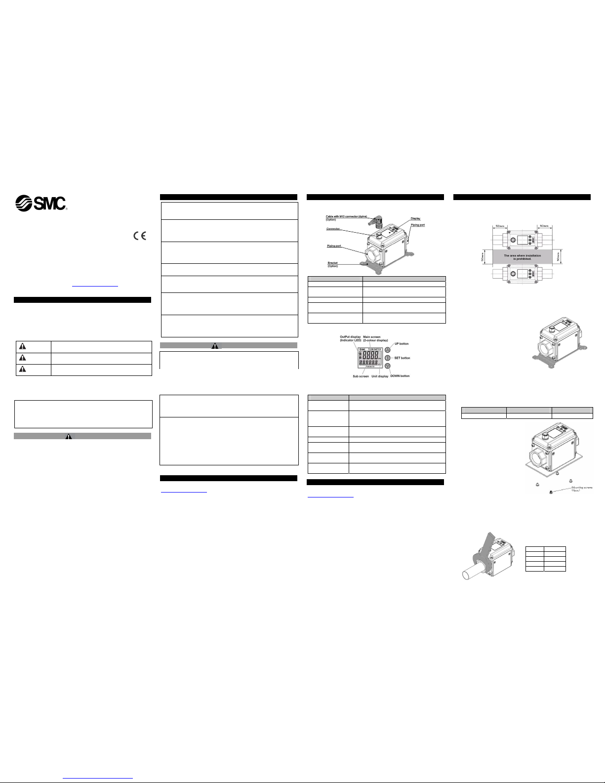
3 Summary of Product parts
3.1 Body
Item Description
Connector Connector for electrical connections.
Cable with M12 connector
Cable to supply power and transmit output
signals.
Piping port Port to connect the fluid.
Bracket
Mounting bracket used to install the
product.
Display
(With display only)
Displays the flow, settings and error codes.
(see below.)
3.2 Display (With display only)
Item Description
Main screen
(2-colour display)
Displays the flow, the status of setting mode and
error codes.
Sub screen
Displays the accumulated flow, set value,
peak/bottom value and line names. In
measurement mode, the set status is displayed.
Output display
(Indicator LED)
Displays the output status of OUT1 and OUT2.
When ON: Orange light is ON.
Unit display Displays the unit selected.
UP button
Selects the mode and the sub screen display, and
increases the ON/OFF set value.
SET button
Press this button to select mode and to confirm a
set value.
DOWN button
Selects the mode and the sub screen display, and
decreases the ON/OFF set value.
4 Mounting and Installation
Refer to the product catalogue or SMC website ( URL
http://www.smcworld.com
) for more detailed information.
4.1 Mounting
• Never mount the product in a location where it will be used as a support.
• Mount the product so that the fluid flows in the direction indicated by the
arrow on the side of the body.
• Check the flow characteristics data for pressure loss and the straight inlet
pipe length effect on accuracy, to determine inlet piping requirements.
• Do not sharply reduce the piping size.
• The piping port and metal part of the body are grounded to DC (-)/ blue.
Note that a power supply with positive ground cannot be used.
4 Mounting and Installation (continued)
• When several sensors are mounted in parallel, do not mount them in the
area where installation is prohibited as shown below.
If the product is mounted in the area where installation is prohibited, the
accuracy will decrease.
4.2 Installation
• Use the product within the specified operating pressure and temperature
range.
• Proof pressure is 2 MPa. Proof pressure could vary according to the fluid
temperature. Check the characteristics data for applying pressure.
Bracket mounting
Mount the product (with bracket)
using the mounting screws (M4 x 4
pcs).
Bracket thickness is approx. 1.6mm.
Refer to the outline dimension
drawing for the bracket thickness
and mounting hole dimensions.
Direct mounting
Mount the product with the screws stated below.
Thread type Nominal thread size Tightening torque
Self tapping screws 3 0.32 ±0.03 Nm
Refer to the dimension drawing
for mounting hole dimensions.
When a self tapping screw is
used, it should not be re-used
several times.
4.3 Piping
When connecting piping to the product, a spanner should be used on
the metal piping attachment only.
Using a spanner on other parts may damage the product.
In particular, do not let the spanner come into contact with the M12
connector.
The connector can be easily damaged.
Width across flats of attachment
Port Width
3/8 24 mm
1/2 28 mm
3/4 35 mm
1 41 mm
LFE**-TFP41
4 Mounting and Installation (continued)
Tighten to the specified torque for piping.
The tightening torque for connection threads is shown in the table below.
Nominal thread size Tightening torque
Rc(NPT)3/8 22 to 24 Nm
Rc(NPT)1/2 28 to 30 Nm
Rc(NPT)3/4 28 to 30 Nm
Rc(NPT)1 36 to 38 Nm
If the tightening torque is exceeded, the product can be damaged. If the
correct tightening torque is not applied, the fittings may become loose.
Avoid any sealing tape getting inside the port.
Ensure there is no leakage from loose piping.
4.4 Wiring
Wiring of connector
Connections should only be made with the power supply turned off.
Use separate routes for the Flow switch wiring and any power or high
voltage wiring. Otherwise, malfunction may result due to noise.
Ensure that the FG terminal is connected to ground when using a
commercially available switch-mode power supply. When a switch-mode
power supply is connected to the product, switching noise will be
superimposed and the product specification can no longer be met.
This can be prevented by inserting a noise filter, such as a line noise
filter and ferrite core, between the switch-mode power supply and the
product, or by using a series power supply instead of a switch-mode
power supply.
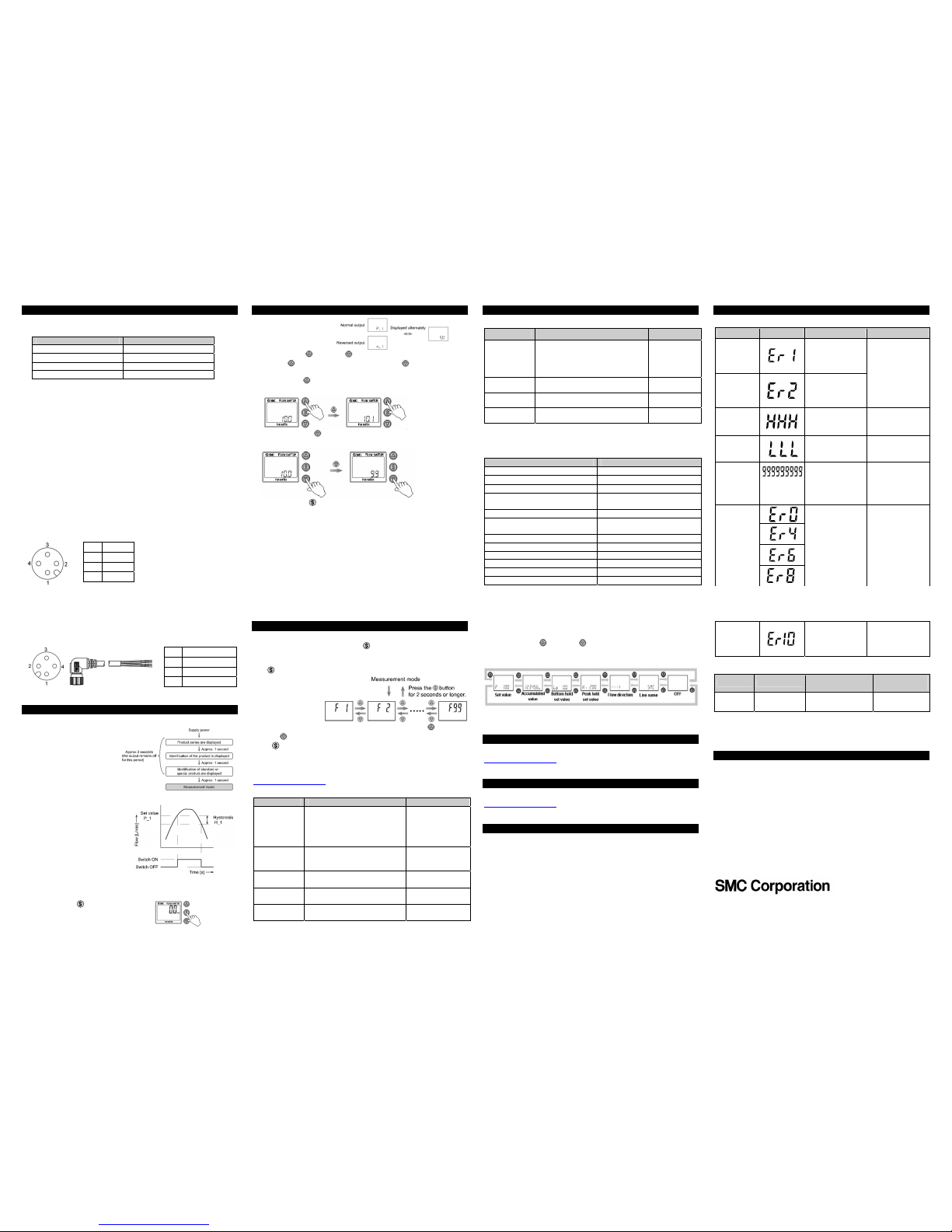
・Pin number of the connector ( on the product )
1 DC(+)
2 OUT2
3 DC(-)
4 OUT1
・Pin number of the connector ( on the cable )
1 DC(+): Brown
2 OUT2: White
3 DC(-): Blue
4 OUT1: Black
∗: When using the lead wire with M12 right angle connector.
5 Flow Setting
5.1 Measurement mode
The mode in which the flow is
detected and displayed, and
the switch function is
operating.
This is the basic operating
mode; other modes should be
selected for set-point and
other function setting changes.
Set ON and OFF points of the
switch output.
(With display only)
Switch operation
When the flow exceeds the set
value, the switch will be turned ON.
When the flow falls below the set
value by the amount of hysteresis
or more, the switch will be turned
OFF.
If the operation shown is
acceptable, keep this setting.
<Operation>
1. Press the SET
button in
measurement mode to display the set
values.
5 Flow Setting (continued)
2. [P_1] or [n_1] and the
set value are displayed
alternately.
3. Press the UP
or DOWN
button to change the set value.
The UP
button is to increase and the DOWN button is to
decrease the set value.
• Press the UP
button once to increase by one digit, press and hold
to continuously increase.
• Press the DOWN
button once to decrease by one digit, press and
hold to continuously decrease.
4. Press the SET button to finish the setting.
The switch turns on within a set flow range (from P1L to P1H) during
window comparator mode.
Set P1L (switch lower limit) and P1H (switch upper limit) using the
setting procedure above.
When reversed output is selected, the main screen displays [n1L] and
[n1H].
For models with 2 outputs, [P_2] or [n_2] will be displayed. Set as
above.
∗: If a button operation is not performed for 30 seconds during the setting
changes, the set value will start flashing.
6 Function Setting
6.1 Function selection mode (With display only)
In measurement mode, press the SET button for 2 seconds or longer,
to display [F 1].
[F] indicates the mode for changing each functional setting. Press the
SET button for 2 seconds or longer to return to measurement mode.
∗
: The sub screen will
display the content
of the function and
the setting
alternately.
The function number is increased and decreased by the UP
and
DOWN
buttons. Display the required function number and press the
SET button.
6.2 Default settings
The default settings are as follows. If these settings are acceptable, retain
for use.To change a setting, refer to the SMC website (URL
http://www.smcworld.com
) for more detailed information or contact SMC.
●[F 1] Setting of OUT1
Item Content Default setting
Output mode
Selects the switch output type
from: Instantaneous flow (either
hysteresis or window comparator
mode), accumulated flow or
accumulated pulse output.
Hysteresis mode
Reversed
output
Selects which type of switch
output is used, normal or
reversed.
Normal output
Set value
Sets the ON or OFF point of the
switch output.
50% of rated flow
Hysteresis
Setting of hysteresis can prevent
chattering.
5% of rated flow
Display colour
The display colour can be
selected.
Output ON: Green
Output OFF: Red
6 Function Setting (continued)
●[F 2] Setting of OUT2
Item Content Default setting
Output mode
Selects the switch output type from:
Instantaneous flow (either hysteresis
or window comparator mode),
accumulated flow or accumulated
pulse output.
Hysteresis
mode
Reversed
output
Selects which type of switch output
is used, normal or reversed.
Normal output
Set value
Sets the ON or OFF point of the
switch output.
50% of rated
flow
Hysteresis
Setting of hysteresis can prevent
chattering.
5% of rated
flow
∗: The display colour is linked to the setting of OUT1, and cannot be set for
OUT2.
●Other parameter settings
Item Default setting
[F 3] Response time 1 second
[F10] Sub screen Display of flow direction
[F20] External input Accumulated flow external reset
[F22] Analogue output
Free range analogue output for
instantaneous flow: OFF
[F30] Accumulated flow OFF [not held]
[F32] Flow direction mode,
Reversed flow detection
Normal flow
OFF
[F80] Power saving mode No setting [display is turned on]
[F81] Security code OFF
[F82] Input of line name No name [∗∗∗∗∗∗]
[F90] Setting of all functions OFF
[F98] Output check OFF
[F99] Reset to the default settings OFF
6.3 Sub screen display
In measurement mode, the sub screen display can be temporarily changed
by pressing the UP
or DOWN
buttons.
∗: After 30 seconds, it will automatically return to the display selected in
[F10].
The set values and accumulated output of OUT2 cannot be displayed.
(example shown is for 20 L/min type)
7 Other Settings
Refer to the product catalogue or SMC website ( URL
http://www.smcworld.com
) to obtain more detailed information about other
settings.
8 Outline Dimensions
Refer to the product catalogue or SMC website ( URL
http://www.smcworld.com
) to obtain more detailed information about outline
dimensions.
9 Maintenance
■ How to reset the product after a power cut or when the power has
been unexpectedly removed
The settings of the product are retained from before the power cut or deenergizing.
The output condition also recovers to that before the power cut or deenergizing, but may change depending on the operating environment.
Therefore, check the safety of the whole installation before operating the
product.
10 Troubleshooting
10.1 Error indication (With display only)
Error Name Display Content Remedy
OUT1
over current
error
The switch output
load current has
exceeded 80 mA
(OUT1).
OUT2
over current
error
The switch output
load current has
exceeded 80 mA
(OUT2).
Turn the power off
and remove the
cause of the over
current. Then turn
the power on again.
Excessive
instantaneous
flow
The flow rate has
exceeded the flow
rate range
Reset applied flow to
a level within the
flow range.
Reverse flow
error
The flow rate is in
the reverse direction
to the settings.
Apply the flow in the
correct direction.
Excessive
accumulated
flow
(Displays 「999」
and 「999999」
alternately)
The accumulated
flow range has been
exceeded.
Clear the
accumulated flow.
(applicable only if
the accumulated
flow is used)
System error
Internal data error
has occurred.
Turn the power off
and turn it on again.
Sensor error
The power supply
voltage has
exceeded the range
of 24 V ±10%.
Check the power
supply voltage, and
turn the power off
and on again.
10.2 Cross-reference for troubleshooting
Problem Probable cause
Recommended error
handling
Recommended
action
Output
error
Insufficient fluid
supply
Confirm whether the
fluid path is full
Fill the fluid path
If the error cannot be reset after the above measures are taken, please
contact SMC.
11 Contacts
AUSTRIA (43) 2262 62280-0 LATVIA (371) 781 77 00
BELGIUM (32) 3 355 1464 LITHUANIA (370) 5 264 8126
BULGARIA (359) 2 974 4492 NETHERLANDS (31) 20 531 8888
CZECH REP. (420) 541 424 611 NORWAY (47) 67 12 90 20
DENMARK (45) 7025 2900 POLAND (48) 22 211 9600
ESTONIA (372) 651 0370 PORTUGAL (351) 21 471 1880
FINLAND (358) 207 513513 ROMANIA (40) 21 320 5111
FRANCE (33) 1 6476 1000 SLOVAKIA (421) 2 444 56725
GERMANY (49) 6103 4020 SLOVENIA (386) 73 885 412
GREECE (30) 210 271 7265 SPAIN (34) 945 184 100
HUNGARY (36) 23 511 390 SWEDEN (46) 8 603 1200
IRELAND (353) 1 403 9000 SWITZERLAND (41) 52 396 3131
ITALY (39) 02 92711 UNITED KINGDOM (44) 1908 563888
URL : http// www.smcworld.com (Global) http// www.smceu.com (Europe)
Specifications are subject to change without prior notice from the manufacturer.
© 2012 SMC Corporation All Rights Reserved.
 Loading...