

Page 1
Doc.No.LV50***-OMQ0004-B
Product
Electromagnetic Type Digital flow switch
Model/ Series/ Product No.
LFE####
SMC Corporation
Page 2

-1-
No.LV50***-OMQ0004-B
Contents
Safety Instructions 2
Model Indication and How-to-Order 11
Summary of product parts 13
Definitions and terminology 14
Mounting and Installation 15
Installation 16
Piping method 17
Wiring 18
Maintenance 20
Troubleshooting 21
Specifications 22
Table of Specifications 22
Applicable Fluids 23
Characteristics Chart 24
Analogue output 27
Dimensions 28
Page 3
-2-
No.LV50***-OMQ0004-B
Safety Instructions
These safety instructions are intended to prevent hazardous situations and/or equipment damage. These
instructions are categorized into three groups, "Caution", "Warning" and "Danger" depending on the level of
hazard and damage, and the degree of emergency. They are all important notes for safety and must be followed
in addition to International Standards (ISO/ IEC), Japan Industrial Standards (JIS)
*1)
and other safety
regulations
*2)
.
*1) ISO 4414: Pneumatic fluid power -- General rules relating to systems.
ISO 4413: Hydraulic fluid power -- General rules relating to systems.
IEC 60204-1: Safety of machinery -- Electrical equipment of machines. (Part 1: General requirements)
ISO 10218-1992:Manipulating industrial robots-Safety.
JIS B 8370: Pneumatic fluid power - General rules relating to systems
JIS B 8361: Hydraulic fluid power - General rules relating to systems
JIS B 9960-1: Safety of machinery - Electrical equipment of machines (Part 1: General requirements)
JIS B 8433-1993: Manipulating industrial robots - Safety, etc
*2) Labor Safety and Sanitation Law, etc.
Caution
Caution indicates a hazard with a low level of risk, which if not avoided, could result in minor or
moderate injury.
Warning
Warning indicates a hazard with a medium level of risk, which if not avoided, could result in
death or serious injury.
Danger
Danger indicates a hazard with a high level of risk, which if not avoided, will result in death or
serious injury.
Warning
(1) The compatibility of the product is the responsibility of the person who designs the equipment or
decides its specifications.
Since the product specified here is used under various operating conditions, its compatibility with specific
equipment must be decided by the person who designs the equipment or decides its specifications based on
necessary analysis and test results. The expected performance and safety assurance of the equipment will be
the responsibility of the person who has determined its compatibility with the product. This person should also
continuously review all specifications of the product referring to its latest catalog information, with a view to
giving due consideration to any possibility of equipment failure when configuring the equipment.
(2) Only personnel with appropriate training should operate machinery and equipment.
The product specified here may become unsafe if handled incorrectly.The assembly, operation and
maintenance of machines or equipment must be performed by an operator who is appropriately trained and
experienced.
(3) Do not service or attempt to remove product and machinery/equipment until safety is confirmed.
1. The inspection and maintenance of machinery/equipment should only be performed after measures to
prevent dropping of driven objects or run-away of machinery/equipment have been confirmed.
2. When the product is to be removed, confirm that the safety measures as mentioned above are implemented
and the power from any appropriate source is cut, and read and understand the specific product precautions
of all relevant products carefully.
3.Before machinery/equipment is restarted, take measures to prevent unexpected operation and malfunction.
(4) Contact SMC beforehand and take special consideration of safety measures if the product is to be
used in any of the following conditions.
1. Conditions and environments outside of the given specifications, or used outdoors or in a location exposed
to direct sunlight.
2.Installation of equipment in conjunction with atomic energy, railways, air navigation, space, shipping,
vehicles, military, medical treatment, combustion and recreation, or equipment in contact with food and
beverages, emergency stop circuits, clutch and brake circuits in press applications, safety equipment or
other applications unsuitable for the standard specifications described in the product catalog.
3. An application which could have negative effects on people, property, or animals requiring special safety
analysis.
4. Use in an interlock circuit, which requires the provision of double interlock for possible failure by using a
mechanical protective function, and periodical checks to confirm proper operation. Check the product
regularly in order to confirm normal operation.
Page 4
-3-
No.LV50***-OMQ0004-B
Safety Instructions
Caution
The product is provided for use in manufacturing industries.
The product herein described is basically provided for use in manufacturing industries.
If the product is being considered for use in other industries, consult SMC beforehand and exchange
specifications or a contract if necessary.
If anything is unclear, contact your nearest sales branch.
Limited Warranty and Disclaimer/ Compliance Requirements
The product used is subject to the following “Limited warranty and Disclaimer” and “Compliance Requirements”.
Read and accept them before using the product.
[Limited Warranty and Disclaimer]
(1) The warranty period of the product is 1 year in service or within 1.5 years after the product is
delivered.
*3)
Also, the product may have specified durability, running distance or replacem ent parts. Please consult
your nearest sales branch.
(2) For any failure or damage reported within the warranty period which is clearly our responsibility, a
replacement product or necessary parts will be provided.
This limited warranty applies only to the SMC product independently, and not to any other damage
incurred due to the failure of the product.
(3) Prior to using SMC products, please read and understand the warranty terms and disclaimers noted
in the specified catalog for the particular products.
*3) Vacuum pads are excluded from this 1 year warranty.
A vacuum pad is a consumable part, so it is warranted for a year after it is delivered.
Also, even within the warranty period, the wear of a product due to the use of the vacuum pad or
failure due to the deterioration of rubber material are not covered by the limited warranty.
[Compliance Requirements]
When the product is exported, strictly follow the laws required by the Ministry of Economy, Trade and Industry
(Foreign Exchange and Foreign Trade Control Law).
Page 5
-4-
No.LV50***-OMQ0004-B
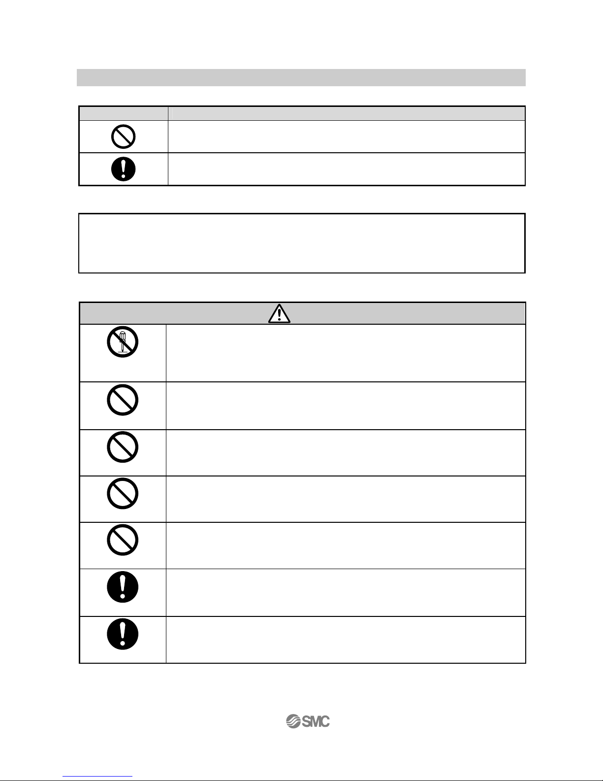
■Explanation of Symbols
Symbol Definition
Things you must not do.
Actual instructions are provided as a drawing or sentence close to this mark.
Things you must do
Actual instructions are provided as a drawing or sentence close to this mark.
■Operator
(1) This Operation Manual is intended for those who have knowledge of machinery using pneumatic
equipment, and have sufficient knowledge of assembly, operation and maintenance of such equipment.
Only those persons are allowed to perform assembly, operation and maintenance.
(2) Read and understand this Operation Manual carefully before assembling, operating or providing
maintenance to the product.
■ Safety Instructions
Warning
Disassembly
prohibited
# Do not disassemble, modify (including the replacement of board) or repair.
Otherwise, an injury or failure can result.
Do not
■Do not operate the product outside of the specifications.
Do not use for flammable or harmful fluids.
Fire, malfunction, or damage to the product can result.
Please check the specifications before use.
Do not
■Do not use in an atmosphere containing flammable or explosive gases.
Fire or an explosion can result.
The product is not designed to be explosion proof.
Do not
■Do not use the product for flammable or highly permeable fluids.
Fire, explosion, breakage or corrosion can result.
Do not
■Do not use the product in a place where static electricity is a problem.
Otherwise failure or malfunction of the system can result.
Instruction
If using the product in an interlocking circuit:
- Provide a double interlocking system, for example a mechanical system.
- Check the product for proper operation.
Otherwise malfunction can result, causing an accident.
Instruction
The following instructions must be followed during maintenance :
- Turn off the power supply
- Stop supplying fluid before maintenance.
It may cause an injury.
Page 6
-5-
No.LV50***-OMQ0004-B
Caution
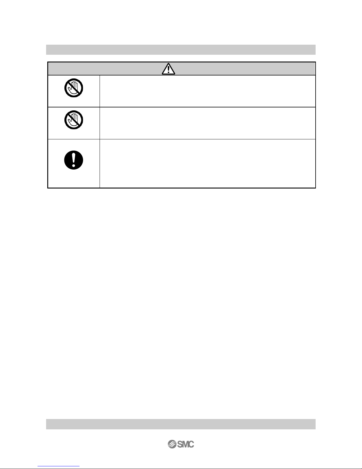
Do not touch
■Do not touch the terminals and connectors while the power is on.
Otherwise electric shock, malfunction or damage to the switch can result.
Do not touch
■Do not touch the piping joint or piping when hot fluid is used.
It may lead to burn.
Check that the piping is cooled down before touching it.
Instruction
# After maintenance is complete, perform appropriate functional inspections and leak
test.
Stop operation if the equipment does not function properly or there is leakage of fluid.
When leakage occurs from parts other than the piping, the product itself may be damaged.
Cut off the power supply and stop the fluid supply.
Do not apply fluid if the system is leaking.
Safety cannot be assured in the case of unexpected malfunction.
■ Handling Precautions
-Follow the instructions given below for selecting and handling.
● The instructions on design and selection (installation, wiring, environment, adjustment, operation,
maintenance, etc.) described below must be followed.
*Product specifications
- Use the specified voltage.
Otherwise failure or malfunction can result.
Insufficient supply voltage may not drive a load due to a voltage drop inside the product.
Verify the operating voltage of the load before use.
Do not exceed the specified maximum allowable load.
This may cause damage or shorten the lifetime of the product.
Data stored by the product is not deleted, even if the power supply is cut off. (Write limit: 1000000 cycles,
Data duration: 20 years after power off.)
- Confirm the pressure loss at the sensor according to the flow rate characteristics (pressure loss) graph
before designing piping.
Confirm pressure loss of the sensor from the flow characteristics chart.
- Take care that pressure exceeding the specified range will not be applied due to water pulsation.
<Examples of measures for reducing water pulsation>
(1) Use a water pulsation resistant valve.
(2) Use elastic piping material such as rubber hose etc. and an accumulator to absorb impact pressure.
Shorten the length of piping as much as possible.
- Use the product within the specified operating pressure and temperature range.
Withstand pressure is 2.0MPa. Withstand pressure depends on fluid temperature. Refer to the chart of
the operating pressure range.
- Reserve a space for maintenance.
When designing an application, allow sufficient clearance for maintenance and inspection.
Page 7

-6-
No.LV50***-OMQ0004-B
● Product handling
Installation
- Tighten to the specified tightening torque.
If the tightening torque is exceeded, the mounting screws and brackets may be damaged. Insufficient torque can
cause displacement of the product from its proper position and the looseness of the mounting screws.
(Refer to Mounting and Installation (page 16 to 21).)
- Be sure to ground terminal FG when using a switch-mode power supply that is commercially obtained.
- Do not use where the product is subjected to vibration or impact.
Otherwise damage to the internal components may result, causing malfunction.
Do not pull the lead wire forcefully, or lift the product by the lead wire. (Tensile strength 49 N or less)
Hold the product body when handling to prevent damage, failure or malfunction.
The product will be damaged, leading to failure and malfunction.
- When multiple sensors are used in parallel, the accuracy is deteriorated if they are mounted too closely
together.
For piping of the pressure switch, hold the piping with a tool on the metal part of the product (piping
attachment).
Holding other parts with a tool may damage the product.
Specifically, make sure that the
tool does not damage the M12 connector.
This will damage the connector.
- Any dust left in the piping should be flushed out by air before connecting the piping to the product.
Failure or malfunction may result.
- Ensure the flow direction of the fluid is aligned with the flow direction indicated on the product label
before installation and piping.
Avoid piping in which the piping size of the IN side of the switch changes suddenly.
If the piping size is reduced sharply or there is a restrictor such as a valve on the IN side, fluid velocity distribution
in the piping will be disturbed, leading to improper measurement. Therefore, the above-mentioned piping should
be connected on the OUT side.
If the OUT side is opened, or flow rate is excessive, cavitations may be generated, which may result in improper
measurement. As a measure against this, it is possible to reduce the cavitations by increasing the fluid pressure.
Take action such as mounting an orifice on the OUT side of the switch, and confirm that there is no malfunction
before handling.
If the orifice of the OUT side is fully closed to operate the pump, the switch may malfunction due to the effect of
pulsation (pressure fluctuation). Ensure that there is no malfunction before usage.
Do not insert metal wires or other foreign matter into the flow path.
This can damage the sensor causing failure or malfunction.
- Never mount the product in a place that will be used as a scaffold during piping.
The product may be damaged if excessive force is applied by stepping or climbing onto it.
Page 8
-7-
No.LV50***-OMQ0004-B
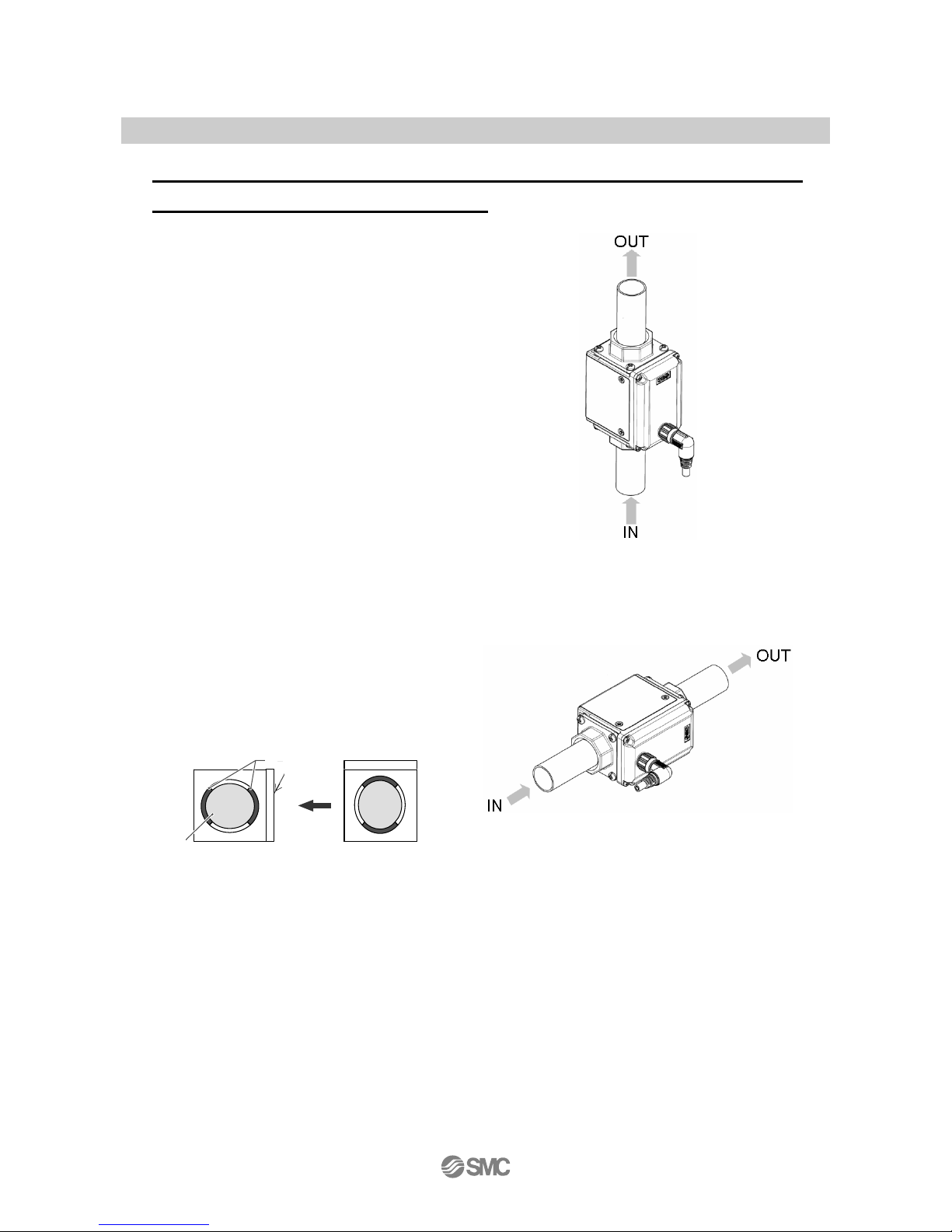
- Design and install the product so that fluid always
fills the detection passage.
1, If the product is used when the detection passage
is not filled, correct detection signal is not output
from the electrodes, making correct measurement
impossible.
For vertical mounting, apply fluid from the bottom
to the top. Bubbles may be generated when
applying fluid from the top to the bottom, leading
to operation failure.
(There should not be a problem as long as the
fluid passage is completely filled with fluid)
2. When the product is mounted vertically, place the
display perpendicular to the floor (to place the
electrodes on the right and the left) to prevent
bubbles from occurring.
After installation, the flow direction can be
changed by setting.
Refer to “Operation” in page 46 for details for
setting.
Down Down
Display
Not
suscep
tible to bubbl
es
Electrode
Fluid passage
S
uscep
tible to bubbl
es
Above Above
Page 9

-8-
No.LV50***-OMQ0004-B
* Wiring (Including connecting/disconnecting of the connectors)
Do not pull hard on the lead wire, or lift the product by holding the lead wires (Tensile strength 49 N or
less). Especially never lift the product equipped with fitting and piping by holding the lead wires.
Damage to the connector, circuit board, cover or internal components may result, causing failure or malfunction.
- Avoid repeatedly bending, stretching or applying a heavy object or force to the lead wire.
Repetitive bending stress or tensile stress can cause the sheath of the wire to peel off, or breakage of the wire.
If the lead wire can move, fix it near the body of the product.
The recommended bend radius of the lead wire is 6 times the outside diameter of the sheath, or 33 times the
outside diameter of the insulation material, whichever is larger.
Replace the damaged lead wire with a new one.
- Wire correctly.
Incorrect wiring can cause malfunction or damage the product.
- Do not perform wiring while the power is on.
Otherwise damage to the internal components may result, causing malfunction.
- Do not route wires and cables together with power or high voltage cables.
Route the wires of the product separately from power or high voltage cables to prevent noise and surge from
entering the product.
- Confirm proper insulation of wiring.
Poor insulation (interference with other circuits, poor insulation between terminals etc.) can apply excessive
voltage or current to the product causing damage.
- Design the system to prevent reverse current when the product is performing an operational check.
Depending on the circuit used, insulation may not be maintained when operation is forced, allowing reverse
current to flow, which can cause malfunction and damage to the product.
Keep wiring as short as possible to prevent interference from electromagnetic noise and surge voltage.
Do not use a cable longer than 10 m.
Wire the DC (-) line (blue) as close as possible to the power supply.
When analog output is used, install a noise filter (line noise filter, ferrite element, etc.) between the
switch-mode power supply and the product.
Page 10

-9-
No.LV50***-OMQ0004-B
Operating environment
- Do not use the product in an environment where the product is constantly exposed to water splashes.
Otherwise failure or malfunction can result. Take measures such as using a cover.
- Do not use in an environment where the product could be exposed to corrosive gas or liquids.
Otherwise damage to the internal parts can result, causing malfunction.
Do not use the product in a place where the product could be splashed by oil or chemicals.
If the product is to be used in an environment containing oils or chemicals such as coolant or cleaning solvent,
even for a short time, it may be adversely affected (damage, malfunction, or hardening of the lead wires).
- Do not use in an area where surges are generated.
When there are machines or equipment that generate large surges near the product (magnetic type lifter, high
frequency inductive furnace, motor, etc.), this can result in deterioration and damage of the internal elements. Take
measures against the surge sources, and prevent the lines from coming into close contact.
Do not use a load which generates surge voltage.
When a surge-generating load such as a relay or solenoid is directly driven, use the product with a surge
absorbing element built-in.
- The product is CE marked, but not immune to lightning strikes. Take measures against lightning strikes
in the system.
- Mount the product in a location that is not affected by vibration or impact.
Failure or malfunction may result.
- Do not use the product in the presence of a magnetic field.
Malfunction can result.
- Do not let foreign matter, such as wire debris, get inside the product.
- In order to avoid failure and malfunction, do not let foreign matter, such as wire debris, get inside the product.
Do not use the product in an environment that is exposed to temperature cycle.
Heat cycles other than ordinary changes in temperature can adversely affect the internal components of the
product.
- Do not expose the product to direct sunlight.
If using in a location directly exposed to sunlight, protect the product from the sunlight.
Failure or malfunction may result.
- Keep within the specified operating fluid and ambient temperature range.
The operating fluid temperature range is 0 to 85 , and ambient temperature range is 0 to 50°C.
If the fluid freezes, it may cause damage and malfunction of the switch, so please take measures to prevent
freezing.
If the temperature of the fluid is lower than the ambient temperature, condensation will be generated which may
damage the product or cause malfunction.
Protection against freezing is necessary.
Avoid abrupt temperature changes even within the specified temperature range.
Failure or malfunction may result.
- Do not operate close to a heat source, or in a location exposed to radiant heat.
Insufficient air quality may cause operation failure.
Page 11

-10-
No.LV50***-OMQ0004-B
* Adjustment and Operation
- Connect a load before turning the power supply on.
If the power supply is turned on with no load, over current may flow, causing the product to break instantly.
- Do not short-circuit the load.
Although error is displayed when the product load has a short circuit, generated over current may lead to the
damage of the product.
- Do not press the setting buttons with a sharp pointed object.
This may damage the setting buttons.
- Supply the power when there is no flow.
- There will be a drift on the display / analog output of approx 2 to 3% for 5 minutes after the power supply
is turned on.
- The product doesn’t produce and output signal for 3 seconds after the power is supplied.
- Perform settings suitable for the operating conditions.
Incorrect setting can cause operation failure.
For details of each setting, refer to page 22 to 55 of this Operation Manual.
- During the initial setting and flow setting, the product will switch the measurement output with the
condition before setting.
Confirm the output has no adverse effect on machinery and equipment before setting.
Stop the control system before setting if necessary.
Do not touch the LCD during operation.
The display can vary due to static electricity.
* Maintenance
・Confirm safety by turning off the power supply and stopping the flow before performing maintenance.
There is a risk of unexpected malfunction.
- Perform regular maintenance and inspections.
There is a risk of unexpected failure of components due to the malfunction of equipment and machinery.
Do not use solvents such as benzene, thinner etc. to clean the product.
This may damage the surface of the body or erase the markings on the body.
Use a soft cloth to remove stains.
For heavy stains, use a cloth soaked with diluted neutral detergent and fully squeezed, then wipe up the stains
again with a dry cloth.
Page 12
-11-
No.LV50***-OMQ0004-B
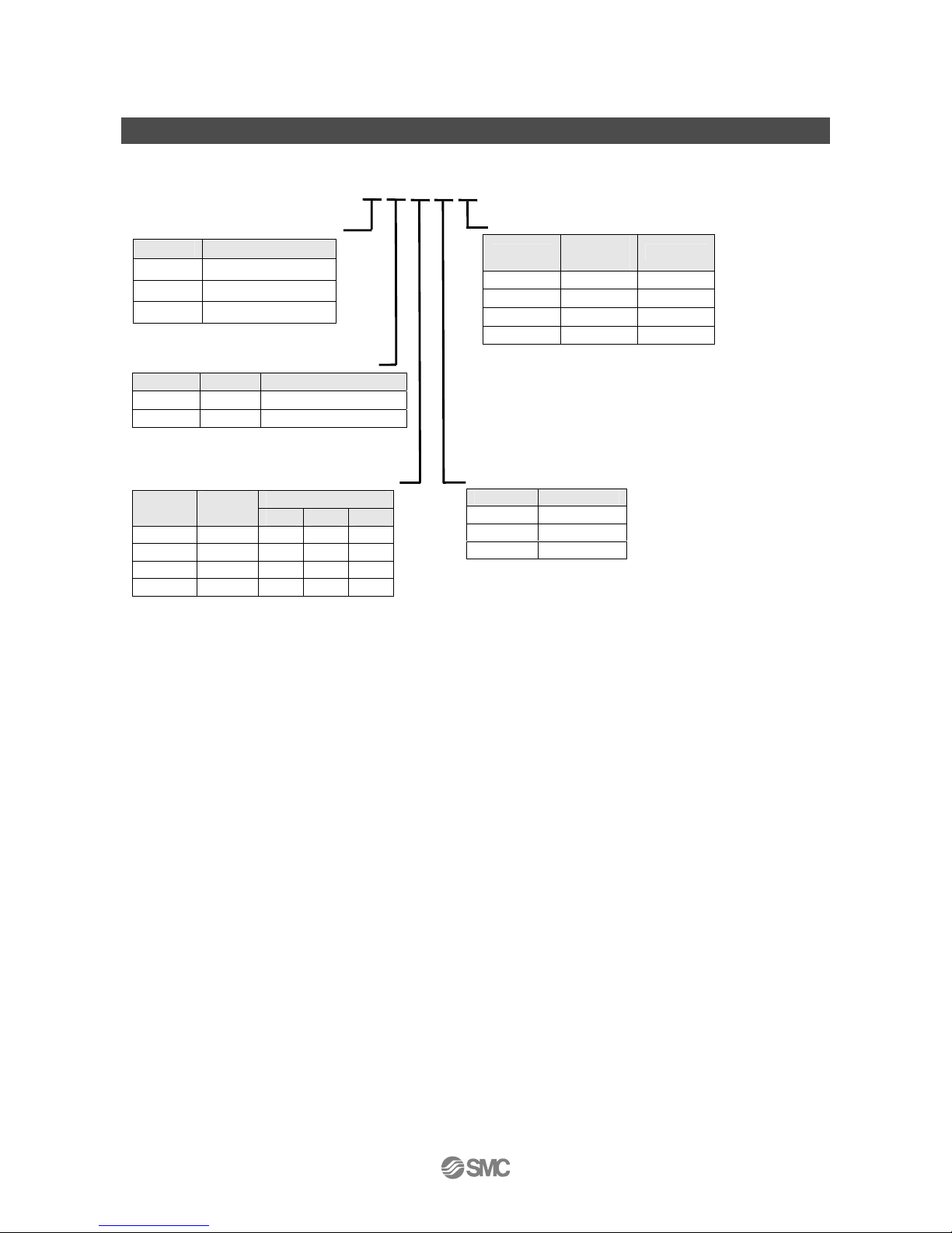
Model Indication Method
Body size (Flow rate range)
Symbol Range
1
0.5~ 20L/min
2
2.5~100L/min
3
5~200L/min
Output Specifications
Symbol OUT1 OUT2
J NPN Analog 1 to 5V
K NPN Analog 4 to 20mA
Piping port size
Rated flow range
Symbol
Port
size
1 2 3
3 3/8 Yes - 4 1/2 Yes - 6 3/4 - Yes 8 1 - - Yes
Thread type
Symbol Description
NIL Rc
N NPT
F G
LFE□□□□□
Option
Symbol
Lead
wire
Bracket
NIL Yes -
1 - 2 Yes Ye s
3 - Yes
Page 13
-12-
No.LV50***-OMQ0004-B
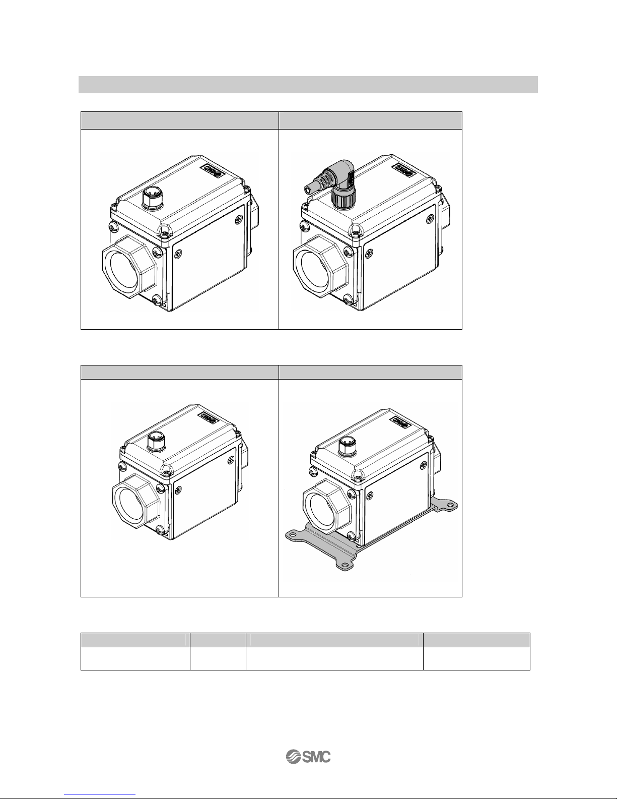
Lead wire
With M12 connector and no lead wire With lead wire and M12 connector
Bracket
None With bracket
Accessories/ Part numbers
If an accessory is required, order using the following part number.
Option Product No. Remarks Weight
With lead wire and M12
connector
LFE-1-A3 Lead wire length: 3 m Approx. 175 g
Page 14
-13-
No.LV50***-OMQ0004-B
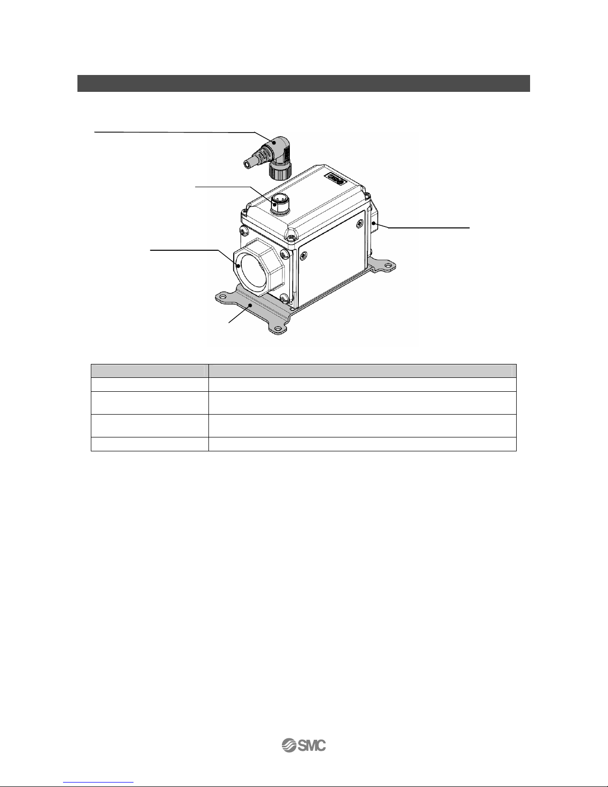
Summary of product parts
Body
Description Function
Connector The part to which lead wires are connected.
With lead wire and M12
connector
This is a cable that supplies power to the product and receives output.
Piping port
For piping connections. Connected to the fluid inlet at IN and to the fluid outlet at
OUT.
Bracket This is a mounting bracket used to install the product.
With lead wire and M12 connector (4 pins)
(Option)
Connector
Piping port(OUT)
Piping port(IN)
Bracket
(Option)
Page 15
-14-
No.LV50***-OMQ0004-B
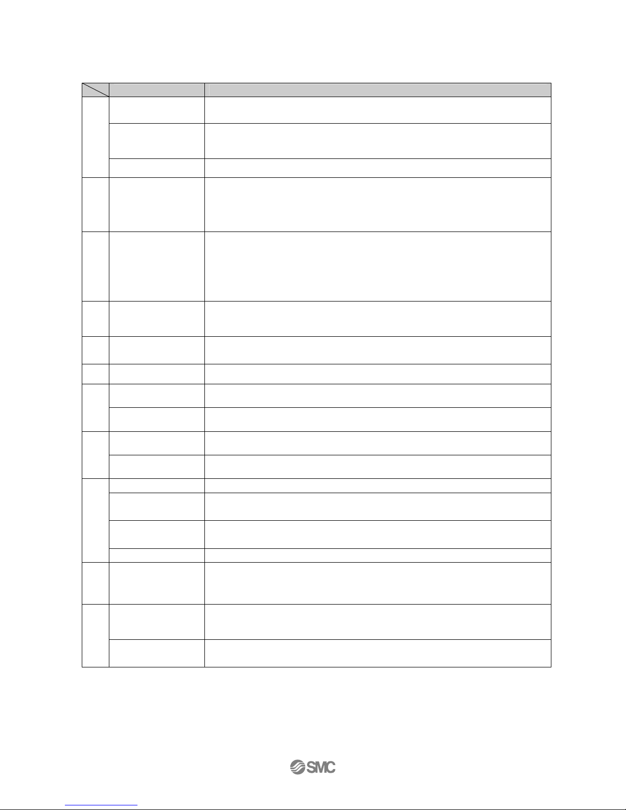
■Definition and terminology
Term Meaning
Ambient temperature
range
Ambient temperature range in which the product can operate.
Analogue output
Outputs a value proportional to the flow rate. When the analog output is in the range 1 to
5V, it will vary between 1 to 5V according to the rate of flow.
The same for analogue output of 4 to -20 mA.
A
Attachment The metal part of both sides of the product to which piping is connected.
C
Cavitation
A phenomenon that may occur in a fluid moving at high speed. In the parts of the fluid
where the pressure is low, vapor bubbles form and then rapidly collapse.
If cavitation is present for a prolonged period, exposed surfaces will be damaged; this is
called cavitation damage or, erosion.
E
Electric conductivity
The electric conductivity is a ratio which shows how easily the electricity flows. The unit
is [S/cm] (siemens/centimeter).
The lower the electric conductivity, the more difficult the electricity flows in the fluid. On
the contrary, the higher the electric conductivity, the easier the electricity flows in the
fluid. The minimum electrical conductivity for fluids for this sensor is 5uS/cm.
Conductivity of tap water is 100 to 200μS/cm.
F
F.S.(full span/full
scale)
This means "full span" or "full scale", and indicates varied analog output range at rated
value.For example, when analog output is 1 to 5 V, F.S.=5[V] – 1[V]=4[V].
(Reference: 1%F.S. = 4[V] × 1% = 0.04[V])
I
Instantaneous flow
The flow passing per unit of time. If it is 10 L/min, there is a flow of 10 L passing through
the device in 1 minute.
M
Measured fluid The fluid(s) that the product can measure.
Operating fluid
temperature
Range of fluid temperature that can be measured by the product.
O
Operating pressure
range
The pressure range in which the product can be used.
Part in contact with
fluid (wetted part)
A part that comes into physical contact with the fluid.
P
Pressure
characteristics
Indicates the change in the display value and analog output when fluid pressure
changes.
Rated flow range The flow range within which the product will meet all published specifications.
Rated pressure range The pressure range that satisfies the specifications.
Repeatability
Reproducibility of the display or analog output value, when the measured quantity is
repeatedly increased and decreased.
R
Response time Time from when the target flow is applied until the flow reaches 63% of the set value.
T
Temperature
characteristics
Indicates the change in the display value and analogue output caused by ambient
temperature or fluid temperature changes.
Water hammer
A momentary steep pressure increase due the spread of pressure by closing a contactor
such as a vlave for an extremely short time while there is a flow.
This pressure increase is known as water hammer or impact pressure.
W
Withstand pressure Burst pressure at which the product is electrically or mechanically damaged.
Page 16
-15-
No.LV50***-OMQ0004-B
Mounting and Installation
Installation
- Use the product within the specified operating pressure and temperature range.
Withstand pressure is 2.0MPa.
Withstand pressure depends on fluid temperature. Refer to the chart of the operating pressure range.
Mounting
- Never mount the switch in a place that will be used as a scaffold.
Mount the product so that the fluid flows in the direction indicated by the arrow on the side of the body.
Check the flow characteristics data for pressure loss and the straight inlet pipe length effect on accuracy
(page 63), to determine inlet piping requirements.
Do not sharply reduce the piping size.
- Piping port and the metal part of the body are grounded to DC(-)/blue line.
Do not use the power supply with positive ground.
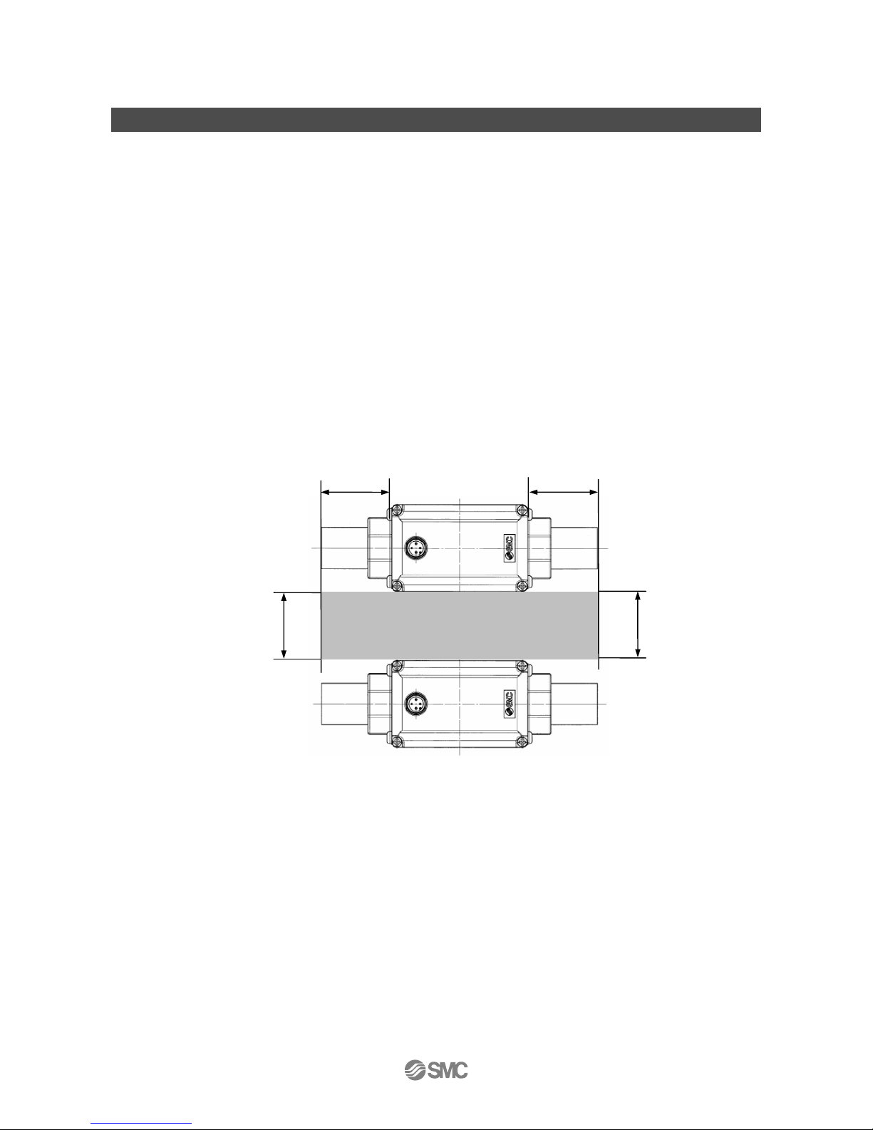
- When multiple sensors are used in parallel, install them outside of the area shown below. (Uninstallable
area)
If the product is mounted in the area where installation is prohibited, the accuracy will decrease.
Uninstallable area
20mm
20mm
50mm
50mm
Page 17
-16-
No.LV50***-OMQ0004-B
■Installation
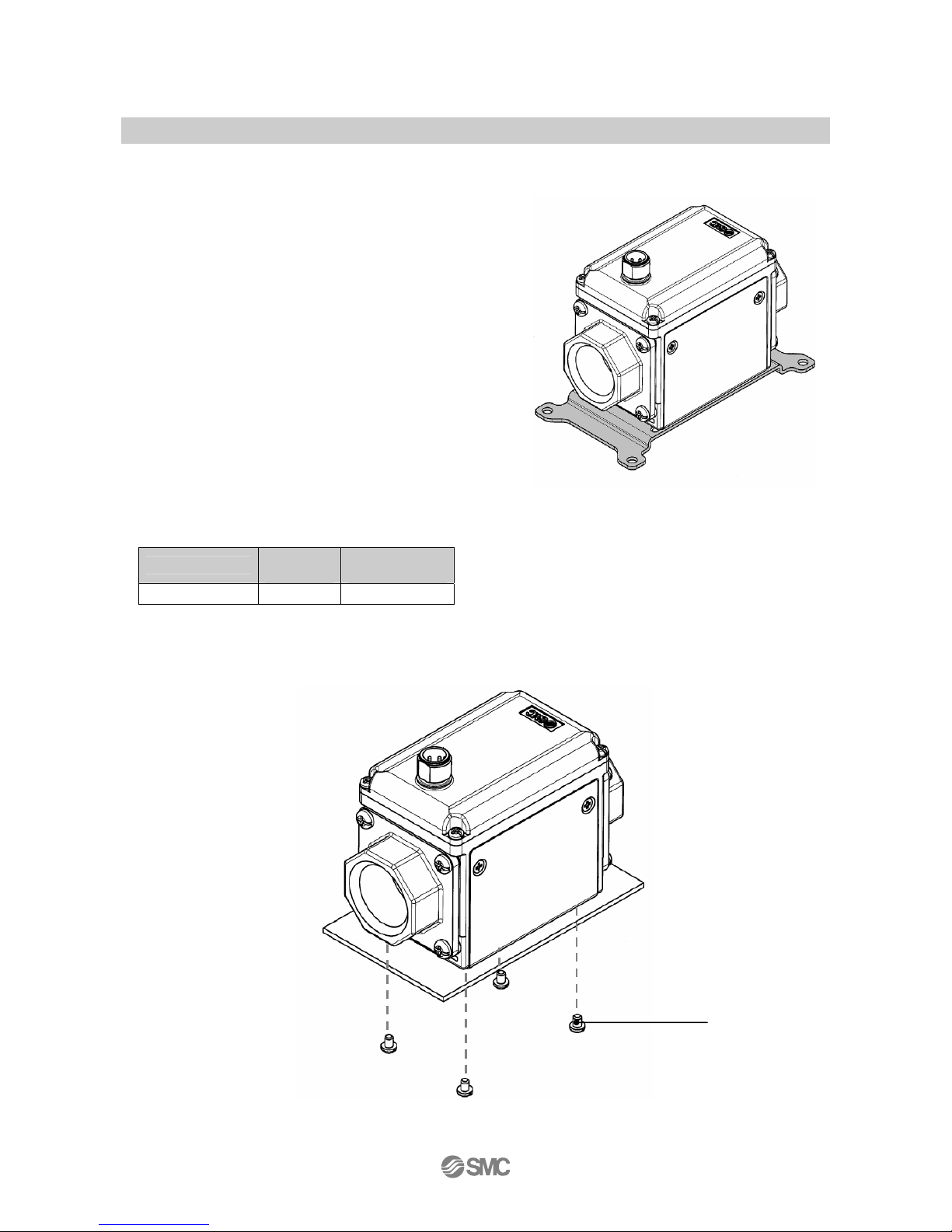
Bracket mounting
Fix the bracket using the mounting screws (Equivalent to
M4: 4 pcs.).
Bracket thickness is approx. 1.6mm
Refer to the valve manifold drawing for dimensions. (Page
67)
Direct mounting
Mount the product with the screw stated below.
Thread type
Nominal
thread size
Tightening
torque
Tapping screw 3 0.32±0.03 Nm
Refer to the outer dimensional drawing (page 67) for the diameter and depth of the mounting screw
holes.
The self tapping screws cannot be reused.
Mounting
screw
(4 pcs.)
Page 18
-17-
No.LV50***-OMQ0004-B
■ Piping method
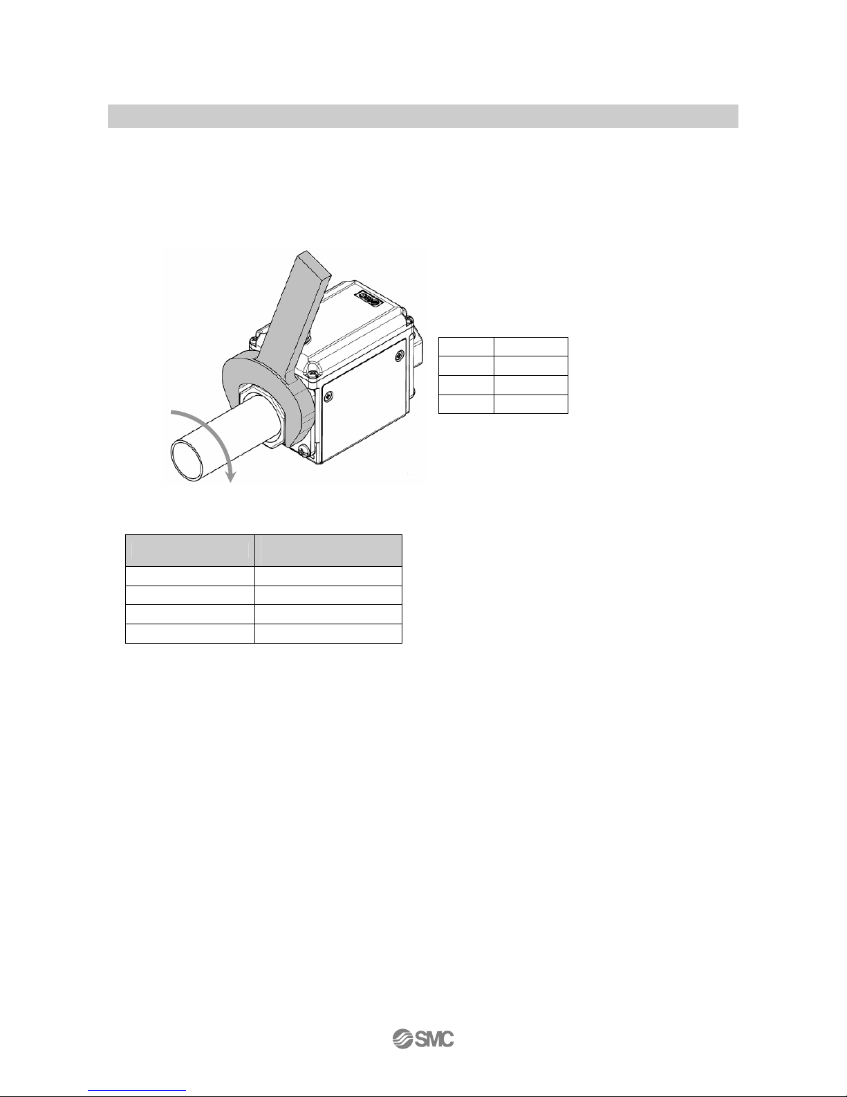
For piping of the product, hold the piping with a tool on the metal part of the piping (piping attachment).
Fixing the product, please turn the pipe.
Using a tool on other parts may damage the product.
Specifically, make sure that the tool does not damage the M12 connector.
This will damage the connector.
Width across flats of attachment
3/8 24 mm
1/2 28 mm
3/4 35 mm
1 41 mm
Tighten to the specified torque for piping
The tightening torque for connection threads is shown in the table below.
Nominal thread size
Appropriate tightening
torque
Rc(NPT)3/8 22 to 24 Nm
Rc(NPT)1/2 28 to 30 Nm
Rc(NPT)3/4 28 to 30 Nm
Rc(NPT)1 36 to 38 Nm
If the tightening torque is exceeded, the product can be broken.
If the tightening torque is insufficient, the mounting screws and brackets may become loose.
Avoid any sealing tape getting inside the piping.
- Ensure that there is no leakage from loose piping.
Page 19
-18-
No.LV50***-OMQ0004-B
■ Wiring
Wiring of connector
Attaching/detaching of the connector should be done while the power supply is turned off.
Use a separate route for the product wiring and any power or high voltage wiring.
Otherwise, malfunction may result due to noise.
Ensure that the FG terminal is connected to ground when using a commercially available switch-mode
power supply.
If the switch-mode power supply is connected for use, switching noise will be superimposed and it will not
be able to meet the product specifications.
This can be prevented by inserting a noise filter such as a line noise filter and a ferrite element between the
switch-mode power supply and the pressure switch, or by using a linear power supply instead of a
switch-mode power supply.
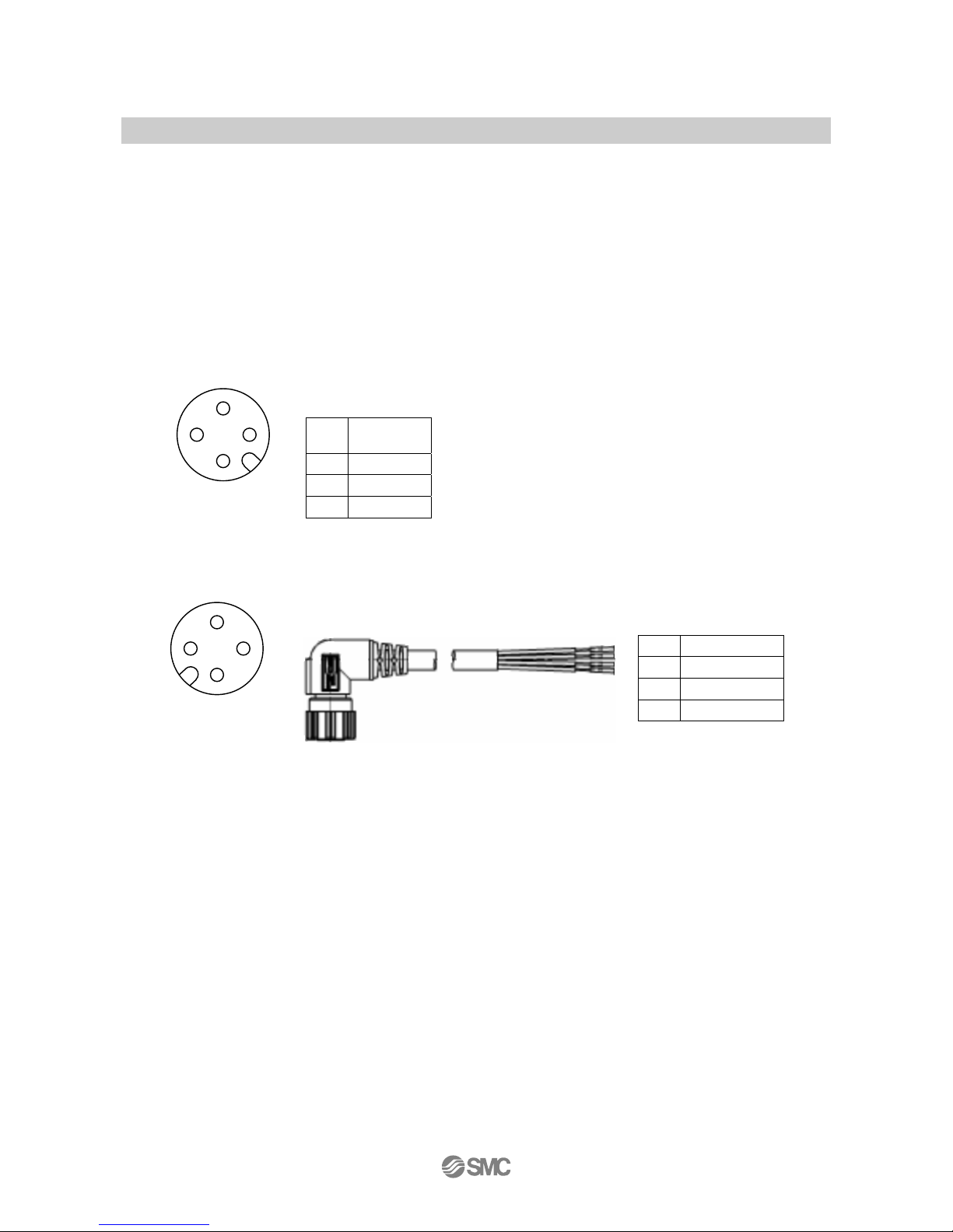
1
DC polar
indication
2 OUT2
3 DC (-)
4 OUT1
1
DC (+): Brown
2 OUT2: White
3
DC (-): Blue
4 OUT1: Black
*: When using the lead wire with M12 connector included with the LFE series.
Cable connector
Connector pin
numbers
4
2
3
1
Connector on the
body
Connector pin
numbers
4
3
1
2
Page 20
-19-
No.LV50***-OMQ0004-B
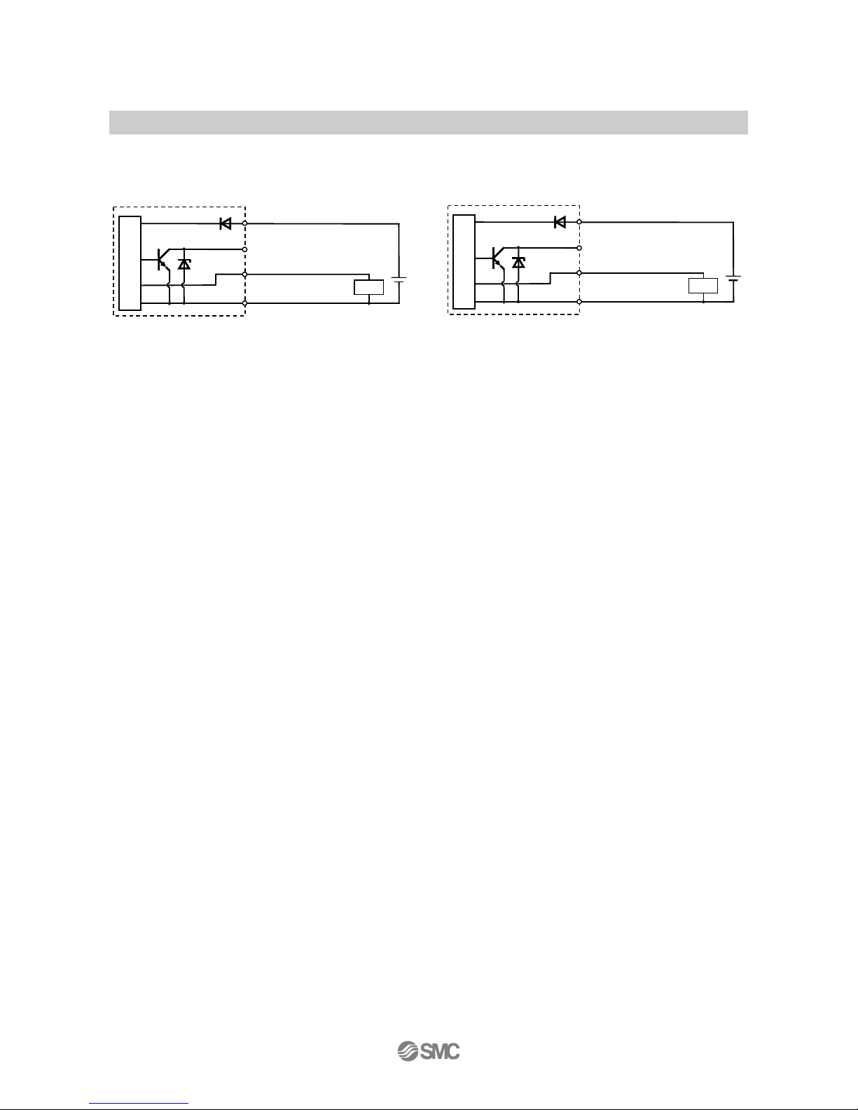
Internal Circuit and Wiring examples
Analog output type
LFE□J□□□
Analog output type
LFE□K□□□
Analog output 1 to 5 V
Output impedance 1 KΩ
Analog output 4 to 20mA
Max. load impedance 600 Ω
Brown DC(+)
Black NC
White OUT2
Blue DC(-)
DC24V
Main circuit
Load
Analog output
Brown DC(+)
Black NC
White OUT2
Blue DC(-)
DC24V
Main circuit
Load
Analog output
Page 21

-20-
No.LV50***-OMQ0004-B
Maintenance and Inspection
How to reset the product after a power cut or when the power has been unexpectedly removed
The settings of the product are retained from before the power cut or de-energizing.
The output condition also recovers to that before power cut or de-energizing, but may change depending on
the operating environment. Therefore, check the safety of the whole installation before operating the product.
Page 22
-21-
No.LV50***-OMQ0004-B
Troubleshooting
Troubleshooting
Applicable Flow switch: LFE series
If an operation failure of the flow switch occurs, please confirm the cause of failure from the flow chart below.
If a cause applicable to the failure cannot be identified and normal operation can be recovered by
replacement with a new flow switch, this indicates that the flow switch itself was faulty. The damage to the
Flow switch may have been caused by operating environment (network construction, etc.). Consult with SMC
separately to obtain countermeasures.
Cross-reference for troubleshooting
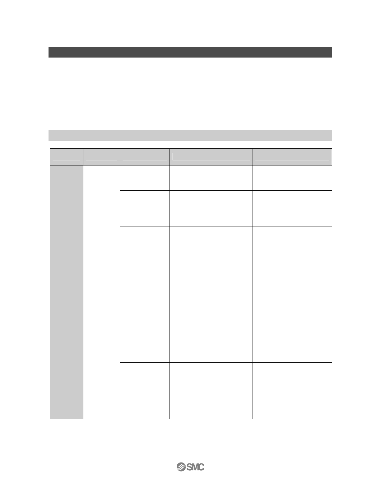
Fault Problem Possible cause Investigation method Countermeasure
Incorrect wiring
Check if the brown wire DC (+),
blue wire DC (-) and white wire
(OUT2) are connected.
Check and correct the wiring.
No output
Loose connector
Check the connection of the
connector.
Connect the connector.
Foreign matter in
the sensor fluid
passage
Check the presence of foreign
matter
Remove foreign matter.
Piping is
connected in the
wrong direction.
Confirm whether the mounting
direction of the product
corresponds to the flow direction.
Make the mounting direction
correspond to the flow
direction.
Insufficient water
supply
- Confirm whether the fluid path
is full.
Fill up the fluid path.
There are bubbles
in the fluid path.
Check there is no air bubble in
the tank.
Change the layout of piping to
prevent air bubbles from
occurring.
Pulsation in the
flow.
Confirm whether the supply
pressure fluctuates, or whether
pulsation is generated due to the
characteristics of the compressor
or pump used as the pressure
source.
Change to a pump with less
pulsation.
Install a tank to reduce the
pressure fluctuation.
Change the piping to elastic
piping such as rubber hose.
Leakage occurs
Check for air leakage due to
insufficient tightening of the
screw of the piping and/or
improper sealing.
Tighten to the specified torque
when piping and/or apply the
seal tape once again.
Output
signal is
abnormal
Unstable
output
Noise
Confirm that there is no power
line or high voltage line that can
be a noise source in the wiring
route.
Do not route wires and cables
together with power or high
voltage cables.
Page 23
-22-
No.LV50***-OMQ0004-B
Specifications
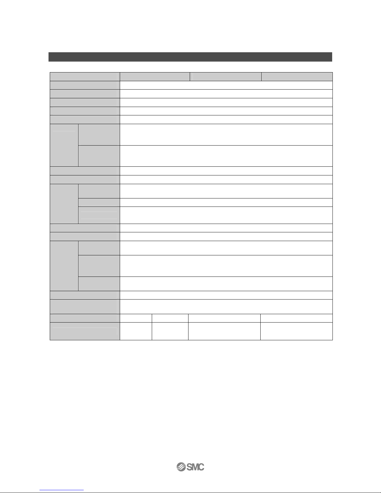
■ Specifications Specification of the product
Model LFE1 LFE2 LFE3
Applicable Fluids
※
1
Conductive fluids which do not corrode the fluid contact materials.
※
1
Applicable fluidconductivity
※
1
5μS/cm or more (micro Siemens/cm)
Detecting method Electro static cupacity
Fluid temperature
※
2
0 to 85oC (No condensation or freezing)
Repeatability
Analog output: ±1.5%F. S.
Ambient
temperature
characteristics
±5%F.S.(25
o
C reference)
Temperat
ure
character
istics
Fluid
temperature
characteristic
±5%F.S.(25
o
C reference)
Operating pressure range
※
2
0 to 1 MPa
Withstand pressure
※
2
2 MPa
Response
※
3
time
0.5 s
Voltage output Output voltage: 1 to 5 V, Output impedance: 1 kΩ min.
Analogue
output
Current output Output current : 4 to 20 mA Max. load impedance 600 Ω
Power supply voltage
DC24 V±10%
Current consumption 42mA or less (Load current is not included)
Enclosure
rating
IP65
Ambient
temperature
range
0 to 50oC (No condensation or freezing)
Environm
ental
Ambient
humidity range
Operation, Storage: 35 to 85%RH (No condensation)
Standards CE marking, RoHS
Material of fluid contact
parts
PPS、FKM、C37
Piping port size 3/8(10 A) 1/2(15 A) 3/4(20 A) 1(25 A)
Weight(Body)
※
4
Approx.
335 g
Approx.
395 g
Approx. 515g Approx. 675 g
※1: Refer to P.23 [Applicable fluids list].
※2: When fluids with high temperature are used, the available pressure range will be reduced. (See [operating pressure range] on page
26 for details.
※3: The response time is when the set value is 63% in relation to the step input.
※4: When options are used, add the weight of the option parts.
Page 24
-23-
No.LV50***-OMQ0004-B
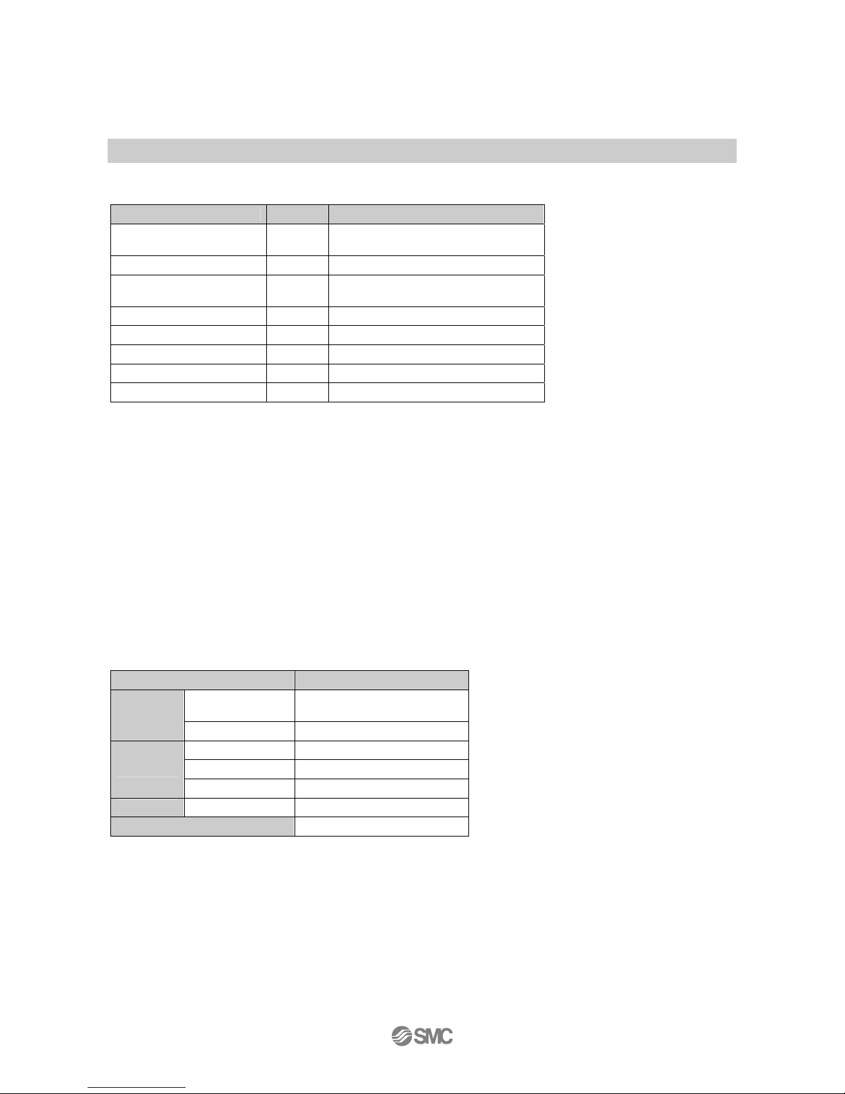
■ Applicable Fluids
Applicable fluid list
Substance description Result Remarks
Water ○
Conductivity of tap water: 100 to
200μS/cm
Deionized water X The electric conductivity is too low.
Water base coolant ○
When the ratio of water is 50% or
more.
Oil X The electric conductivity is too low.
Oil base coolant X The electric conductivity is too low.
Sea water X Corrosive to the sensor electrodes
GALDEN®
X The electric conductivity is too low.
FluorinertTM X The electric conductivity is too low.
*: The applicable fluid list should be used as a guide.
1- Operate fluids with electric conductivity of 5μS/cm or more.
Note that this product can not be used for fluids with low conductivity.
This product cannot be used for fluids that do not conduct electricity such as De-ionized water and oil.
The electric conductivity is a ratio which shows how easily the electricity flows.
2- If insulating material gets stuck inside of the piping, it may cause an error.
Remove the foreign material stuck inside of the piping with a brush for washing test tubes so that internal rubber piping
will not be damaged.
3- If conductive materials such as metal get stuck to the interior surface in the piping, the switch may
malfunction.
Remove the foreign material as mentioned above.
4- If stray electrical currents are flowing through the fluid to be measured, the switch may malfunction.
Beware that electrical leakage currents may be generated by equipment around the flow sensor such as pumps, valves
and metal piping when this equipment is at different electrical potentials in relation to earth ground.
Cable with M12 connector lead wire (LFE-1-A3)
Item Specifications
Nominal cross
section
AWG21
Conductor
O.D. approx. 0.9 mm
Material Non-lead heat resistant PVC
O.D. approx. 1.7 mm
Insulator
Colours Brown, White, Black, Blue
Sheath Material Lead free heat resistant PVC
Finished O.D. Φ6
Page 25
-24-
No.LV50***-OMQ0004-B
■ Characteristics Chart
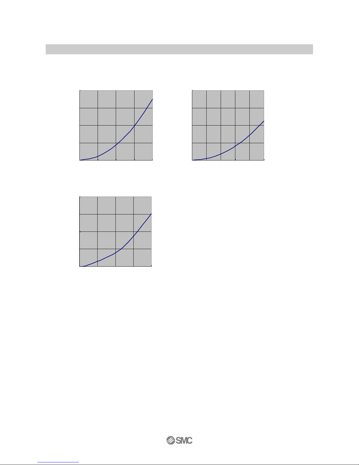
Flow characteristics (pressure loss)
LFE1 LFE2
0
0.005
0.01
0.015
0.02
0 5 10 15 20
Flow rate[L/m in]
P ressurre loss[M Pa]
0
0.005
0.01
0.015
0.02
020406080100
Flow rate[L/m in]
P ressure loss[M P a]
LFE3
0
0.005
0.01
0.015
0.02
0 50 100 150 200
Flow rate[L/m in]
P ressure loss[M P a]
Pressure loss [MPa]
Flow rate [L/min]
Page 26
-25-
No.LV50***-OMQ0004-B
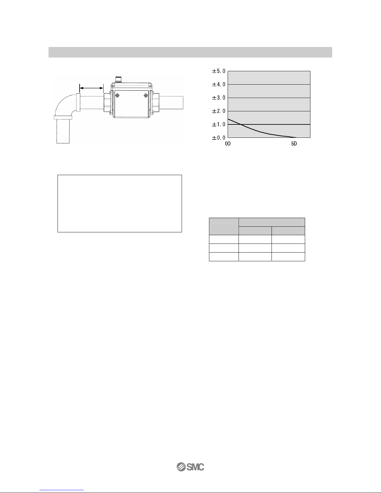
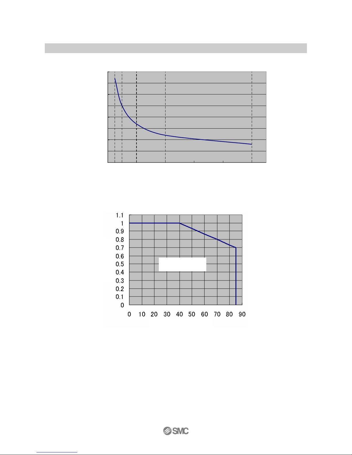
IN side straight pipe length (reference value)
The smaller the piping size, the more the product is
affected by the straight piping length.
The straight piping length shall be 5 times (5D) or
more of the piping size to satisfy and achieve the
stable measurement.
Straight pipe length (mm)
Model
D 5 D
LFE1 11 55
LFE2 21 105
LFE3 27 135
[Measurement condition] [Port size]
Measurement: Tap water LFE1:3/8 inch
Pressure: 0.2 MPa LFE2:3/4 inch
LFE3:1 inch
IN side
Straight
pipe length
OUT side
Change of accuracy [%F.S.]
Straight pipe length
Page 27
-26-
No.LV50***-OMQ0004-B
■ Stability
±0.0
±0.5
±1.0
±1.5
±2.0
±2.5
±3.0
±3.5
±4.0
012345
応答時間[s]
安定性[%F.S.]
■
Operating pressure range
When fluids with high temperature are
used, the operating pressure range will
be reduced. Operate within the range
mentioned above. The proof pressure is
double the operating pressure range.
Stability [%F.S . ]
Response time[s]
Operable range
Pressure [MPa]
Fluid temperature [oC]
Page 28
-27-
No.LV50***-OMQ0004-B
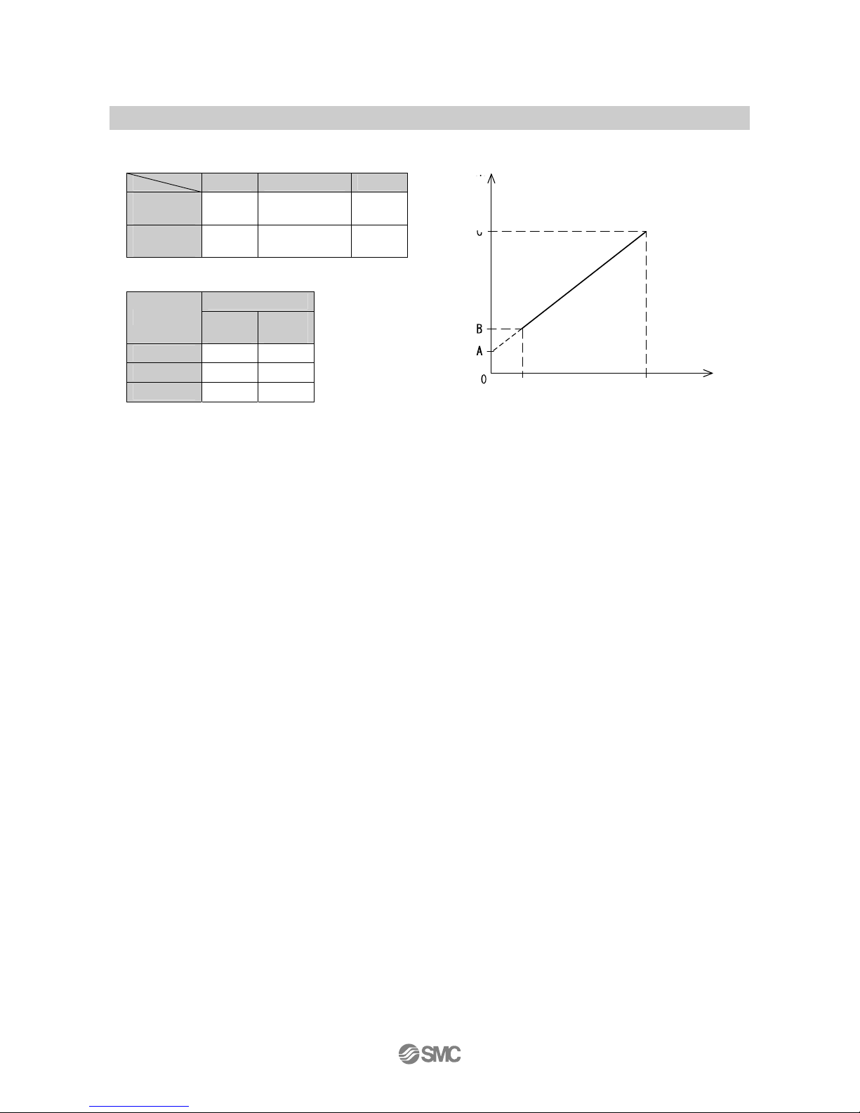
■ Analog output
Flow/Analog output
A B C
Voltage
output
1 V 1.1 V 5 V
Current
output
4 mA 4.4 mA 20 mA
Rated flow[L/min]
Model
Minimum Maximu
m
LFE1 0.5 20
LFE2 2.5 100
LFE3 5 200
Flow rate
Maximum
rated flow
Minimum
rated flow
Out
p
ut
Page 29
-28-
No.LV50***-OMQ0004-B
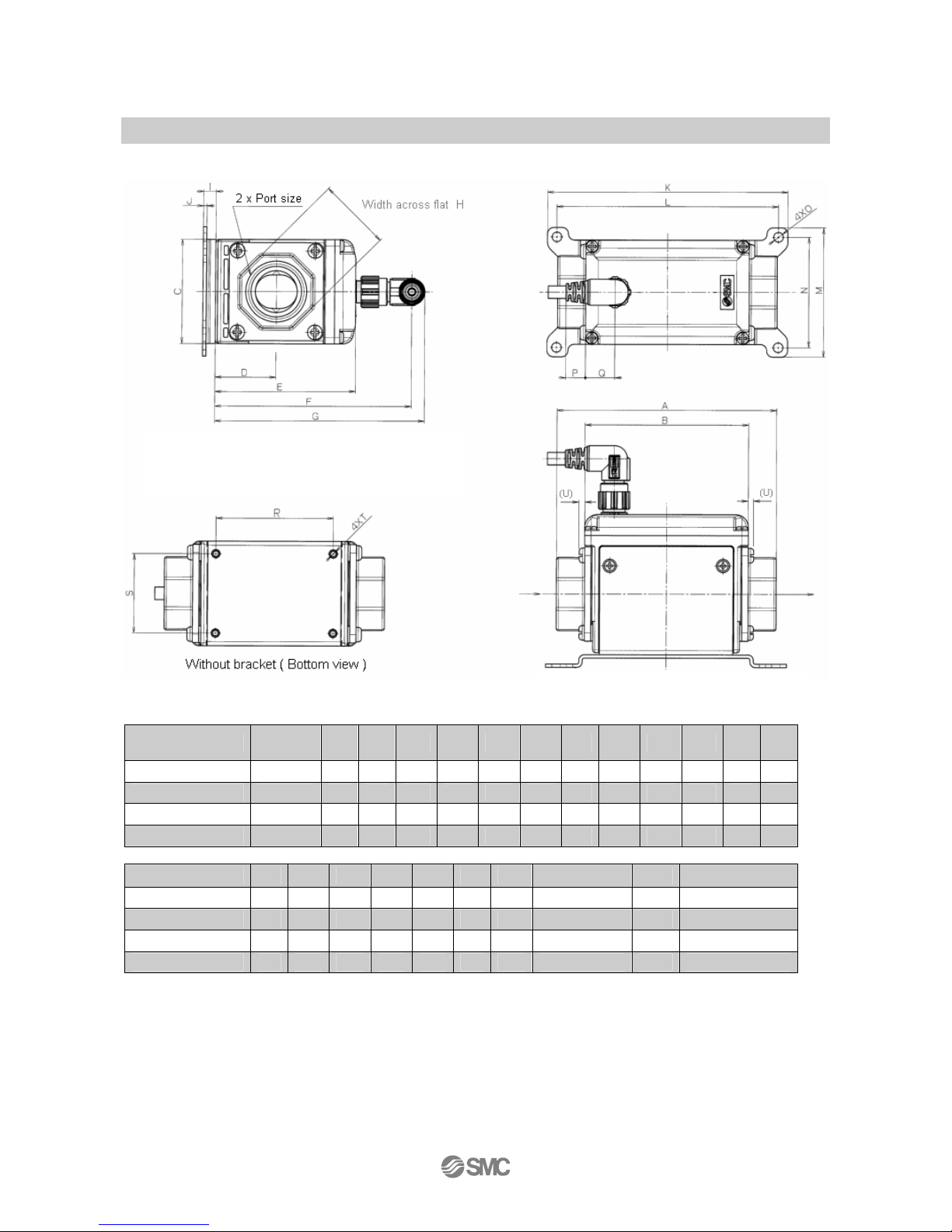
■ Dimensions
Model
Piping
port size
A B C D E F G H I J K L
LFE1□3□□ 3/8 90 73 40 23.5 56 83 89 24 6 1.6 96 87
LFE1□4□□ 1/2 104 73 40 23.5 56 83 89 28 6 1.6 96 87
LFE2□6□□ 3/4 105 78 50 29 67 94 100 35 6 1.6 115 106
LFE3□8□□ 1 120 90 55 32 73 100 106 41 6 1.6 115 106
Model M N O P Q R S T U Bracket weight
LFE1□3□□ 48 39 4.6 12 11.5 52 28 2.5 depth 5.5 2 Approx. 45g
LFE1□4□□ 48 39 4.6 12 11. 5 52 28 2.5 depth 5.5 2 Approx. 45g
LFE2□6□□ 62 53 4.6 9.5 14 56 38 2.5 depth 5.5 2.6 Approx. 70g
LFE3□8□□ 62 53 4.6 3.5 20 68 43 2.5 depth 6.5 2.6 Approx. 70g
Bracket thickness is approx. 1.6mm
Note) The electrical entry for lead wire with
M12 connector does not rotate and is limited
to onl
y
one entry direction.
Page 30
-29-
No.LV50***-OMQ0004-B
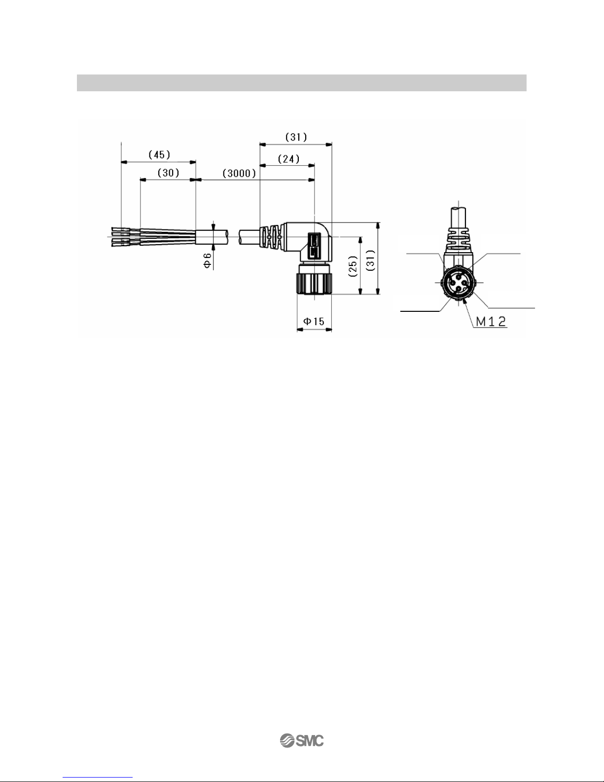
Dimension of the cable with M12 connector lead wire (LFE-1-A3)
4 Black
Blue 3
White 2
1 Brown
Page 31
-30-
No.LV50***-OMQ0004-B
Revision history
4-14-1, Sotokanda, Chiyoda-ku, Tokyo 101-0021 JAPAN
Tel: + 81 3 5207 8249 Fax: +81 3 5298 5362
URL http://www.smcworld.com
Note: Specifications are subject to change without prior notice and any obligation on the part of the manufacturer.
© 2013 SMC Corporation All Rights Reserved
 Loading...