

SMC Networks LEY series,LECSC,LEYG series LECSA,LECSB,LECSS Operation Manual
LEY Series
(Rod type)
Doc. no. LEY-OM00407
LEYG Series
(Guide Rod type)
LECSA
(
Positioning)
LECSS
(
Ⅲ)
(SSCNETⅢ/H)
AC Servo Motor
LECS Series
LECSB
(
)
LECSC
(
)
PRODUCT NAME
Electric Actuator / Rod Type
《 AC Servo Motor 》
MODEL / Series
LEY Series
Applicable models: LEY□ , LEYG□
Pulse input /
CC-Link
Driver
Pulse input
SSCNET

Contents
Safety Instructions ....................................................................2
1. Procedure before ope ra t ion ............................................4
2. Rod type / LEY Series .........................................................13
3. Guide rod type / LEYG Series ........................................17
1.1 Preparation ................................................................... 4
1.2 Startup .......................................................................... 6
1.3 Gain tuning ................................................................... 7
1.3.1 Procedure .................................................................. 7
1.3.2 The recommended the parameter for each driver . 8
2.1 Specification .............................................................. 13
2.2 How to Order .............................................................. 15
2.3 Construction .............................................................. 16
3.1 Specification .............................................................. 17
3.2 How to Order .............................................................. 18
3.3 Construction .............................................................. 19
4. Product Outline ......................................................................20
4.1 System construction ................................................. 20
4.2 Function/Configuration ............................................. 23
5. Wiring of cables / Common precautions .................24
6. Electric actuator s / Comm on pre caut ions ..............25
6.1 Design and selection ................................................. 25
6.2 Mounting .................................................................... 26
6.3 Handling ..................................................................... 27
6.4 Operating environment ............................................. 28
6.5 Maintenance ............................................................... 29
6.6 Precautions for actuator with lock ........................... 29
7. Electric actuator s / Rod Type Common precautions ........30
7.1 Design ........................................................................ 30
7.2 Selection..................................................................... 30
7.3 Handling ..................................................................... 30
7.4 Mounting .................................................................... 32
7.5 Precaution on maintenance ...................................... 35
8. Troubleshooting ....................................................................36
8.1 Alarms and Warning ................................................ 36
-1-
indicates a hazard with a low level of risk which, if not avoided, could result in minor
indicates a hazard with a high level of risk which, if not avoided, will result in death or
Warning
Do not service or attempt to remove product and machinery /equipment until safety is
4. Contact SMC beforehand and take special consideration of safety measures if the product is to
LEY Series / Electric Rod type
Safety Instructions
These safety instructions are intended to prevent hazardous situations and /or equipment damage.
These instructions indicat e the lev el of potentia l hazard w ith the labels o f “Caut ion,” “Warning” or “Dange r.”
They are all important notes for safety and must be followed in addition to International Standards (ISO
/IEC), Japan Industrial St andards (JIS)*1) and other saf ety regulations*2).
*1) ISO 4414: Pneumatic fluid power -- General rules relating to systems
ISO 4413: Hydraulic fluid power -- General rules relating to systems
IEC 60204-1: Safety of machinery -- Electrical equipment of machines (Part 1: General requirements)
ISO 10218-1992: Manipulating industrial robots -- Safety
JIS B 8370: General rules for pneumatic equipment.
JIS B 8361: General rules for hydraulic equipment.
JIS B 9960-1: Safety of machinery – Electrical equipment for machines. (Part 1: General requirements)
JIS B 8433-1993: Manipulating industrial robots - Safety. etc.
*2) Labor Safety and Sanitation Law, etc.
Caution
Warning
Danger
Caution
or moderate injury.
Warning indicates a hazard with a medium level of risk which, if not avoided, could res ult in
death or serious injury.
Danger
serious injury.
1. The compatibility of the product is the responsibility of the person who designs the equipment
or decides its specifications.
Since the product spec ified here is used under var ious operating conditions, its compatibility with specific
equipment must be decided by the person who designs the equipment or decides its specifications based on
necessary analysis and test results.
The expected perform ance and safety assurance of the equipment will be the r esponsibility of the perso n
who has determined its compatibility with the product.
This person should also c ontinuously review all specificatio ns of the product referring to its latest catalog
information, with a v iew to giving d ue considerat ion to any possi bility of equi pment failure when configurin g
the equipment.
2. Only personne l with appropriate training should operate mac hi nery and equipm ent.
The product specified here may become unsafe if handled incorrectly.
The assembly, operation and maintenance of machines or equipment including our products must be
performed by an operator who is appropriately trained and experienced.
3.
confirmed.
The inspection and maintenance of machinery /equipment should only be performed after measures to
prevent falling or runaway of the driven objects have been confirmed.
When the product is to be removed, confirm that the safety measures as mentioned above are implemented
and the power from any appropriate source is cut, and read and understand the specific product precautions
of all relevant products carefully.
Before machinery /equipment is restarted, take measures to prevent unexpected operation and malfunction.
be used in any of t he f oll owing conditions.
1) Conditions and environments outside of the given specifications, or use outdoors or in a place exposed to
direct sunlight.
2) Installation on equipment in conjunction with atomic energy, railways, air navigation, space, shipping,
vehicles, military, medical treatment, combustion and recreation, or equipment in contact with food and
beverages, emergency stop circuits, clutch and brake circuits in press applications, safety equipment or
other applications unsuitable for the standard specifications described in the product catalog.
3) An application which co uld have negat ive effects on people, propert y, or animals requiring special safety
analysis.
4) Use in an inter lock circ uit, which requ ires the prov ision of do uble interloc k for pos sible failure by using a
mechanical protective function, and periodical checks to confirm proper operation.
-2-
Caution
the product in other industries, consult SMC beforehand and exchange specifications
If anything is unclear, contact your nearest sales branch.
Also, the product may have specified durability, running distance or replacement parts. Please
For any failure or damage reported within the warranty period which is clearly our responsibility, a
This limited warranty applies only to our product independently, and not to any other damage
erms and disclaimers
due to the deterioration of rubber material are not covered by the limited warranty.
by the Ministry of Economy, Trade and
LEY Series / Electric Rod type
Safety Instructions
The product is pr ovided for use in manufacturing industries.
The product herein described is basically provided f or peaceful use in manufacturing industries.
If considering using
or a contract if necessary.
Limited warranty and Disclaimer /Compliance Requirements
The product used is subject to the following “Limited warranty and Disclaimer” and “Compliance
Requirements”.
Read and accept them before using the product.
Limited warran ty and Disclaimer
The warranty period of the pr od uct is 1 year in service or 1.5 years after the product i s delivered.*3)
consult your nearest sal es branch.
replacement product or necessary parts will be provide d.
incurred due to the failure of the product.
Prior to using SMC products, please read and understand the warranty t
noted in the specified cat a log for the p a r t icular products.
*3) Vacuum pads are excluded from this 1 year warranty.
A vacuum pad is a consumable part, so it is warranted for a year after it is delivered.
Also, even within the warranty period, the wear of a product due to the use of the vacuum pad or failure
Compliance Requirem e nts
When the product is exported, strictly follow the laws required
Industry (Foreign Exchan ge and Foreign Trade Control Law).
-3-
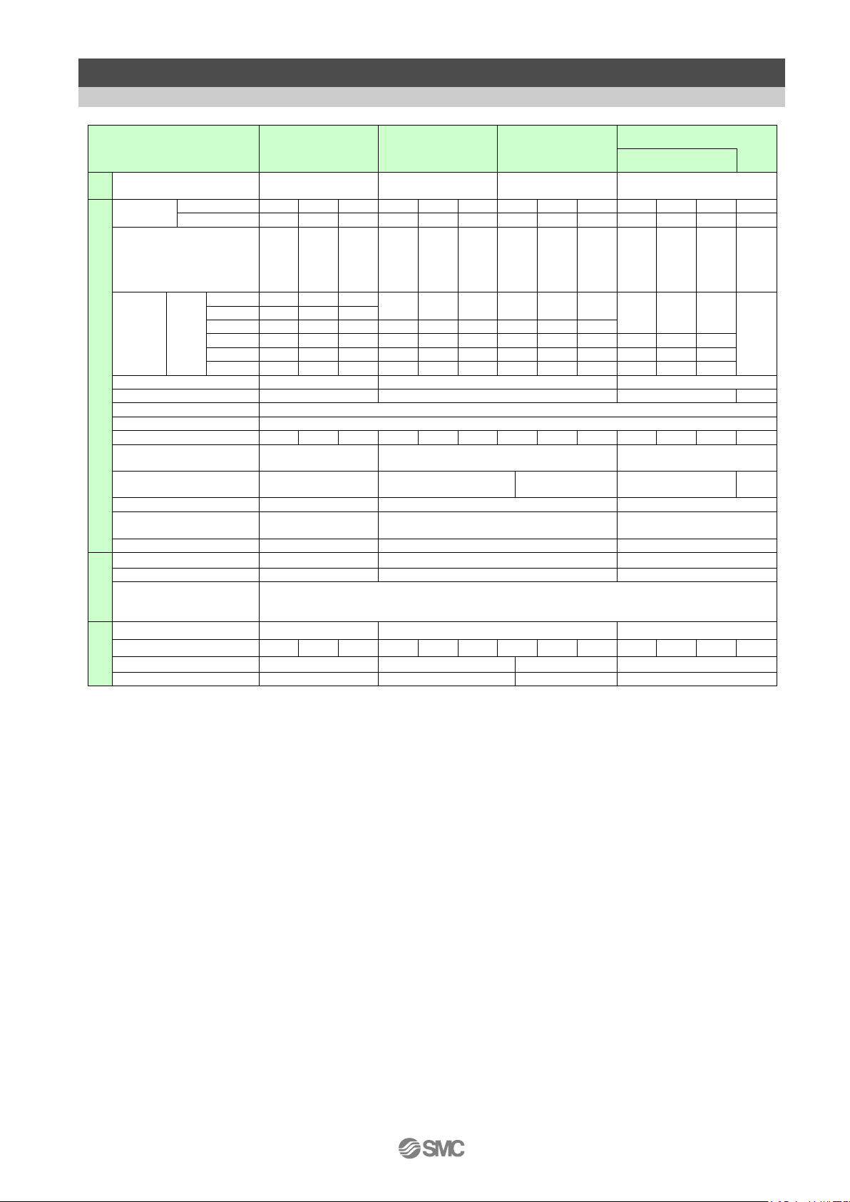
No.
Part name
Qty
(1)
Electric Actuator /LEY Series
1
(2)
Driver / LECS Series
1(in case with driver)
(3)
Motor cable
(4)
Encoder cable
(5)
Lock cable
(6)
I/O Connector
1(in case with I/O connector )
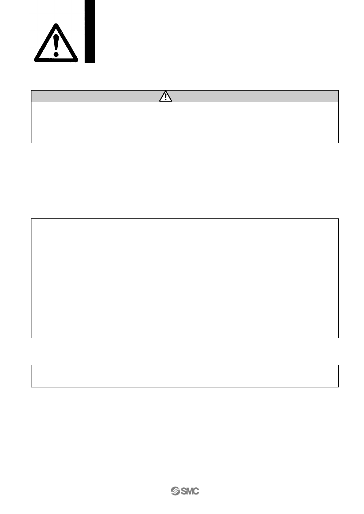
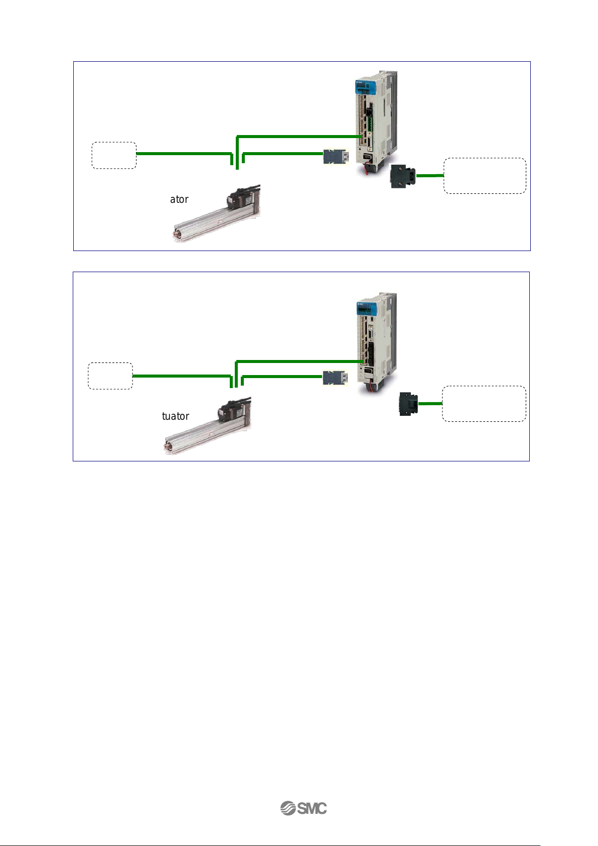
LECSA(Pulse input / Positioning)
(2) Driver
(3) Motor cable
(4) Encoder cable
(1) Electric Actuator
(5) Lock cable
(2) Driver
(3) Motor cable
(4) Encoder cable
(1) Electric Actuator
(5) Lock cable
LECSB(Pulse input)
(6) I/O Connector
(6) I/O Connector
1. Procedure before opera t ion
1.1 Preparation
(1) Items to be prepared
Please check on the label, and the quantity of accessories, to confirm that it is the product that was
ordered.
Table 1. Componets
Pre-installed (1)
(in case with cable)
DC24V
PC, PLC, etc
DC24V
PC, PLC, etc
-4-
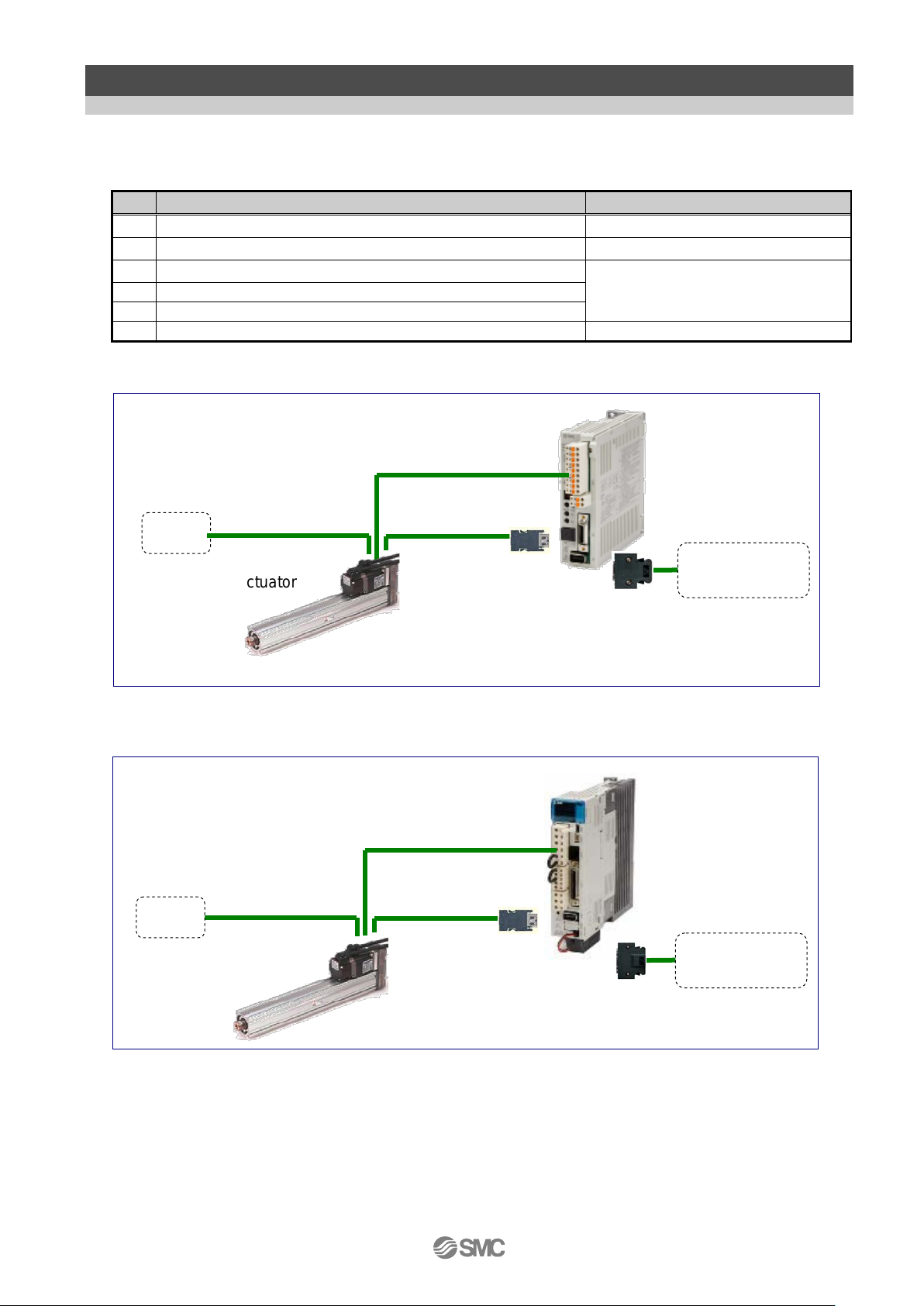
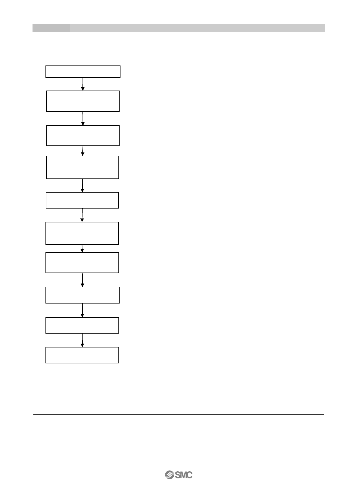
LECSC(CC-Link)
(2) Driver
(3) Motor cable
(4) Encoder cable
(1) Electric actuator
(5) Lock cable
(2) Driver
(3) Motor cable
(4) Encoder cable
(1) Electric actuator
(5) Lock cable
LECSS(SSCNET III) /LECSS-T ( SSCNET III / H )
(6) I/O connector
(
I/O connector
DC24V
Host controller,
etc
DC24V
Host controller,
etc
6)
Refer to the “ Electric actuator / Common precautions 6.2 Mounting No.11” for details and for cable
connection methods.
-5-
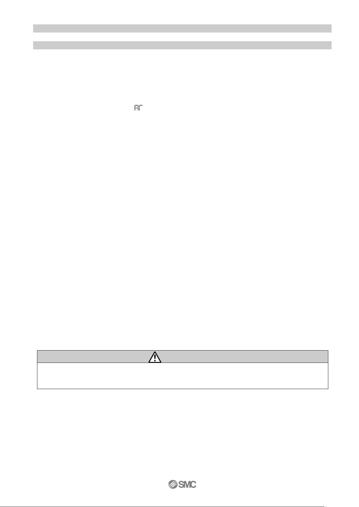
Wiring check
circuit power supply
I/O signal wiring and
during power-on
Confirm that the cables to the driver and actuator are
Check the surrounding environment (cable routing and
Follow the procedure shown in the "Driver Operation
Check the wiring of the input and output signals and
according to the procedure shown in the "Driver
control mode and each control value.
Follow the procedure shown in the "Driver Operation
Use the test operation mode (JOG operation) at the
slowest speed and check whether the servo motor
rotates.
Operation with a vibration might be done according to the
In that case, adjust gain. (Refer to section 1.3)
Check if the cables to the driver and actuator are
Stops command to stop the operation.
- - -
- - -
- - -
- - -
- - -
- - -
- - -
- - -
- - -
- - -
1)CC-Link cable (LECSC), SSCNETIII cable (LECSS)
1.2 Startup
When switching the power on for the first time, follow the startup procedure below.
Refer to the “Driver operation manual” for wiring method and deta iled pr ocedure.
connected correctly.
Surrounding
environment check
Power-on of the contrd
cables check
Parameter setting
Power-on of the main
circuit power supply
Test oper ation
(JOG operation)
impurity such as wire offcuts or metallic dust) of the driver
and the servo motor.
Manual" to supply power to t he pr oduct.
cables1)
Operation Manual".
Set the parameters as necessary, such as selecting the
Manual" to supply power to t he pr oduct.
2)
Gain tuning
Actual operation
Stop
2)When using test operation mode (JOG operation), the LECSC and LECSS need the
MR-Configurator, the LECSS-T needs the MR-Configurator2.
condition.
connected correctly.
-6-
Warning
Refer to "The recommend ed t he parameter for each dri ver" for the parameter.
1.3 Gain tuning
1.3.1 Procedure
Here are the steps for basic gain tuning.
Refer to the “Driver operation manual” for details and for tuning methods other than shown below.
●For LECSA (Pulse input / Positio ni ng)
A. One-touch tuning
During motor driving, push “AUTO” button on the front of the driv er for three seconds.
When display panel becomes “ ”, push “AUTO” button again.
⇒The gain (including filter, etc) is adjuste d automatically.
When the error occurs, refer to the “Driver operation manual”.
B. Auto tuning (Mode1) 1)
Do this operation, if you ar e not satisfied with the result of “One-touch tuning”.
Set parameter N o. PA08 “001”. Afterwards, do 1 and 2 alternately.
1. Reduce value of parameter No.PA09 to be less than present value.
2. Operate and ascer tain the situation.
⇒The gain is adjusted automatically.
●For LECSB (Pulse input), LECSC (CC-Link), LECSS(SSCNETIII)
A. Adaptive filter II
Set parameter N o. PB01 “0001” and drive t he m otor.
⇒The filter is adjuste d aut omatically.
B. Auto tuning (Mode1)
Do this operation, if you ar e not satisfied with the result of “Adaptive f ilter II”.
Set parameter N o. PA08 “0001”. Afterwards, do 1 and 2 a lter nat ely.
1. Reduce value of parameter No.PA09 to be less than present value.
2. Operate and ascer tain the situation.
⇒The gain is adjusted automatically.
●For LECSS-T(SSCNET III/H)
A. Auto tuning (Mode1)
Set parameter N o. PA08 “0001”. Afterwards, do 1 and 2 a lter nat ely.
1. Reduce value of parameter No.PA09 to be less than present value.
2. Operate and ascer tain the situation.
⇒The gain is adjusted automatically.
B. Robust filter
Do this operation, if you ar e not sat isfied with the result of “Auto tuning”.
Set parameter N o. PE41 “0001” and drive t he m otor.
⇒The filter is adjuste d aut omatically.
A mechanical resonance may occ ur depending on the configurat ion or t he mounting orientati on of the
transferred object. Plea se change the appropriate parameter in the initial setting.
1) The auto tuning mode 1 may not be perfor m ed pr operly if the following conditions are not satisfied.
・Time to reac h 2,000rpm is the acceleration/deceleration time constant of 5[s] or less.
・Speed is 150rpm or higher.
・Load to motor inertia is 100 times or less.
・The acceleration/dece leration is 10% or more of the rated torque.
-7-
LEY25/LEYG25
LEY25D/LEYG25D
LEY32/LEYG32
LEY32D/LEYG32D
Lead symbol
A B C A B C A B C A B C Lead
12 6 3
12 6 3
20
10 5 16 8 4
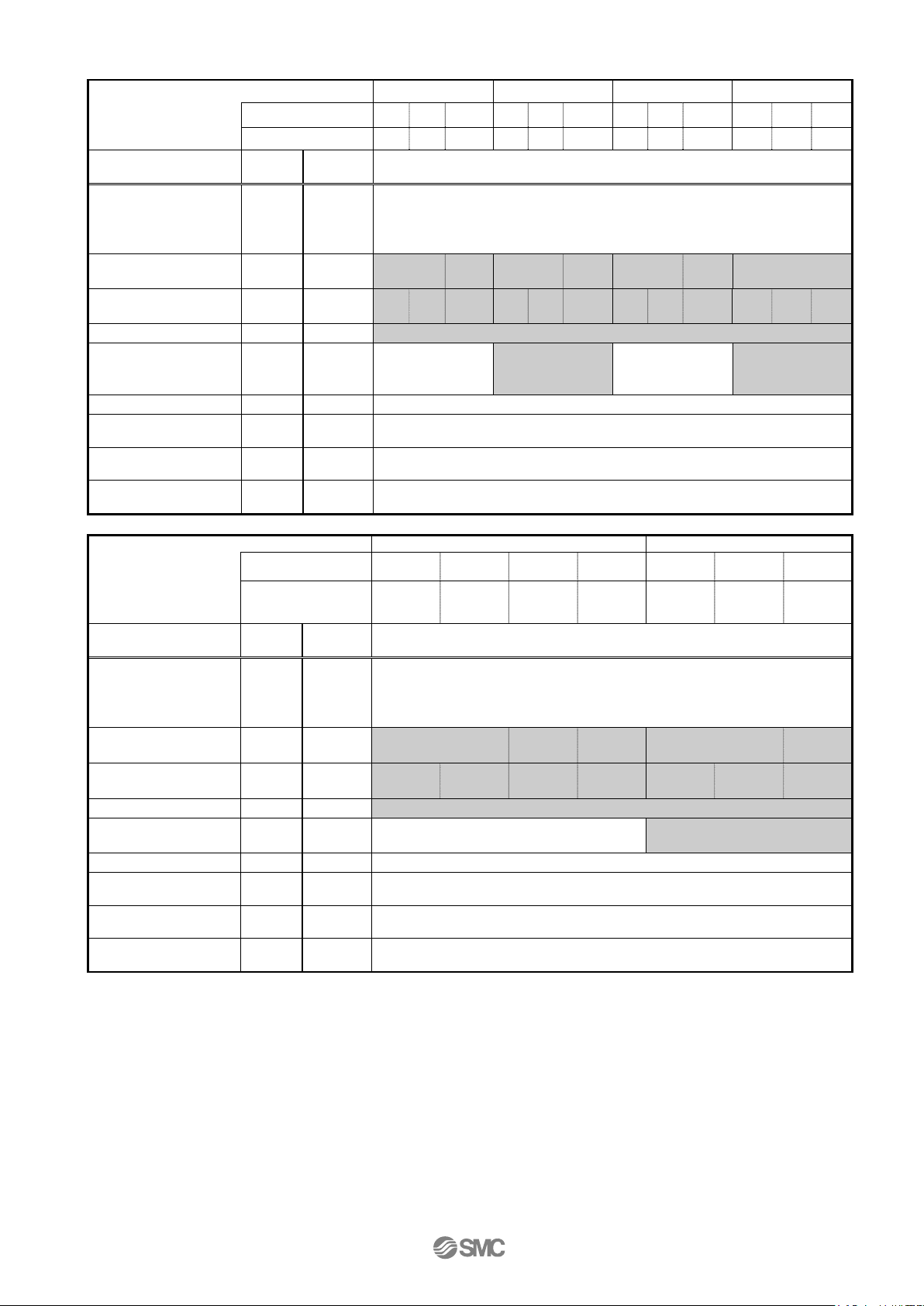
Parameter
Para. No
Initial value
Recommended value
Number of command input pulses per
revolution *3
Electronic gear numerator *3
PA06
1
100 (Positioning mode: 10)
Electronic gear denominator *3
PA07
1
12 6 3
12 6 3
20
10 5 16 8 4
Feel length multiplication (STM) (Multiplier)
PE02
0000
0000 (Less than stroke 1000) / 0001 (Stroke 1000 or more)
Home position return type
PE03
0010
□□□3 (Stopper type)
Home position return direction
PE03
0010
□□1□(Motor side)
Home position return Speed (rpm)
PE04
500
150
300
600
150
300
600
90
180
360
112
225
450
Home position return/JOG operation
acceleration/deceleration time constants (msec)
Home position return position data (μm)
PE08 0 -2000(Less than stroke 1000) / -200 (Stroke 1000 or more)
Stopper type home position return
stopper time (msec)
Stopper type home position return torque limit
value (%)
Regenerative option
PA02
000
000 (Non)/ 002 (LEC-MR-RB032)
0
(+:Counter motors side)
1
(+:Counter motors side )
0
(+:Counter motors side)
1
(+:Counter motors side )
Adaptive tuning mode
PB01
000
000
Load to motor inertia moment ratio
PB06
7
7
Machine resonance suppression filter 1
PB13
4500
4500
Notch shape selection 1
PB14
000
000
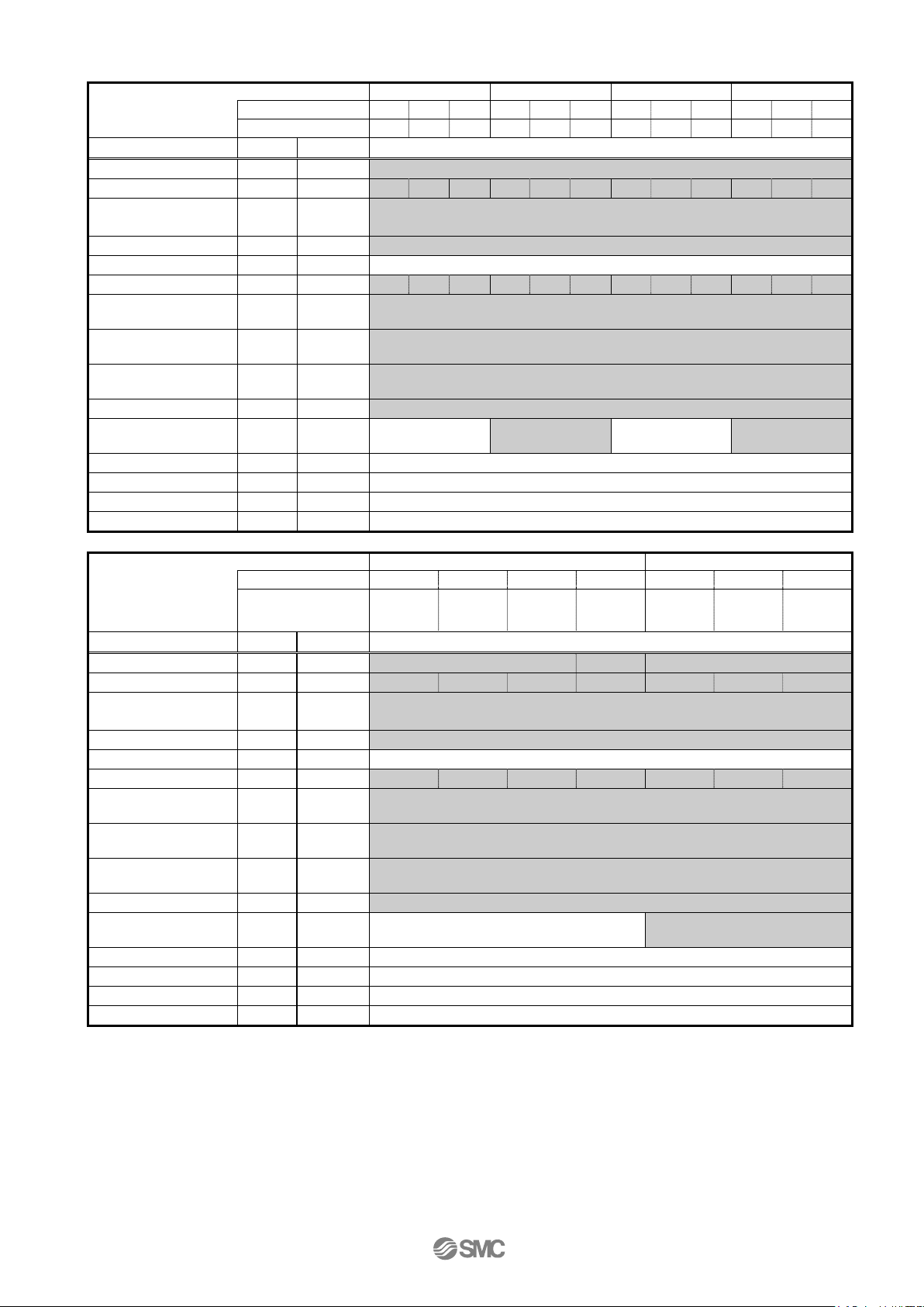
LEY63
LEY63D
Lead symbol
A B C L A B C
5(2.86)
Parameter
Para. No
Initial value
Recommended value
Number of command input pulses per
revolution *3
Electronic gear numerator *3
PA06 1 100 (10)
35 (7)
100 (10)
Electronic gear denominator *3
PA07 1 20
10 5 1(2)
20
10
5
Feel length multiplication (STM) (Multiplier)
PE02
0000
0000 (Less than stroke 1000) / 0001 (Stroke 1000 or more)
Home position return type
PE03
0010
□□□3 (Stopper type)
Home position return direction
PE03
0010
□□1□(Motor side)
Home position return Speed (rpm)
PE04
500
90
180
360
629
90
180
360
Home position return/JOG operation
acceleration/decel eration time constants (msec)
Home position return position data (μm)
PE08 0 -4000(Less than stroke 1000) / -400 (Stroke 1000 or more)
Stopper type home position return
stopper time (msec)
Stopper type home position return torque limit
value (%)
Regenerative option
PA02
000
000 (Non)/ 002 (LEC-MR-RB032)/ 003 (LEC-MR-RB12)
Rotation di rection sel ection
PA14 0 0 (+:Counter motors side)
1 (+:Counter motors side )
Adaptive t uning mode
PB01
000
000
Load to motor inertia moment ratio
PB06
7
7
Machine resonance suppression filter 1
PB13
4500
4500
Notch shape selection 1
PB14
000
000
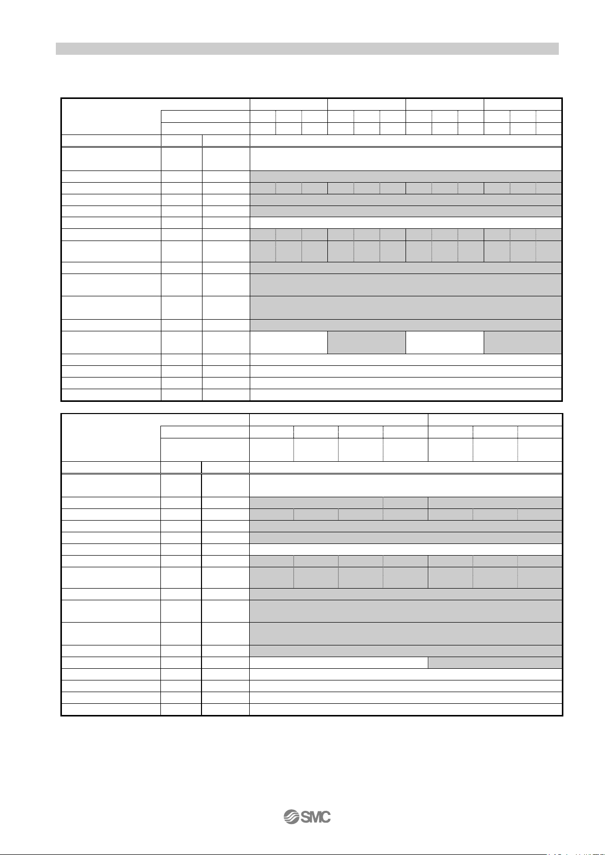
1.3.2 The recomme nde d the parameter for each driver
The recommended the parameter for each driver. Please change the parameter values by use of the
customer.Please refer to the manual of the driver for more details.
[LECSA]
Series
PA05 100 100
Rotation di rection sel ection
Series
PE07 100 600 300 150 600 300 150
PE10 100 200
PE11 15 30
PA14 0
Lead 20 10 5
PA05 100 100
(Pulley raito 4/7)
1000
500 250 800 400 200
20 10 5
PE07 100 1000 500 250 143 1000 500 250
PE10 100 200
PE11 15 30
*1 Parameter is the recommended value. Please change the parameter to make appropriate value for your
operating method.
*2 A mechanical resonance may occur depending on the configuration or the mounting orientation of the
transferred object. Please change the parameter in the initial setting.
*3 When the positioning mode is not set: The travel distance of the actuator per 1 pulse should be 10 [μm/pulse].
When the positioning mode is set: The minimum unit of the travel distance of the actuator should be 1 [μm].
-8-
Initial
value
Number of
revolution
*3
Electronic gear
numerator *3
Electronic gear
denominator *3
15
0
15
0
250 12
5
Regenerative option
PA02
0000
0000 (Non)/ 0002 (LEC-MR-RB032)
0
motors side)
1
motors side )
0
motors side)
1
motors side )
Adaptive tuning mode
PB01
0000
0000
Load to motor inertia
moment ratio
Machine resonance
suppression filter 1
Notch shape selection
1
LEY63
LEY63D
5(2.86)
raito 4/7)
Initial
value
Number of
revolution
*3
Electronic gear
numerator *3
Electronic gear
denominator *3
Regenerative option
PA02
0000
0000 (Non)/ 0002 (LEC-MR-RB032)/ 0003 (LEC-MR-RB12)
Rotation direction
selection
0
(
+:Counter motors side)
1
(+:Counter motors side )
Adaptive tuning mode
PB01
0000
0000
Load to motor inertia
moment ratio
Machine resonance
suppression filter 1
Notch shape selection
1
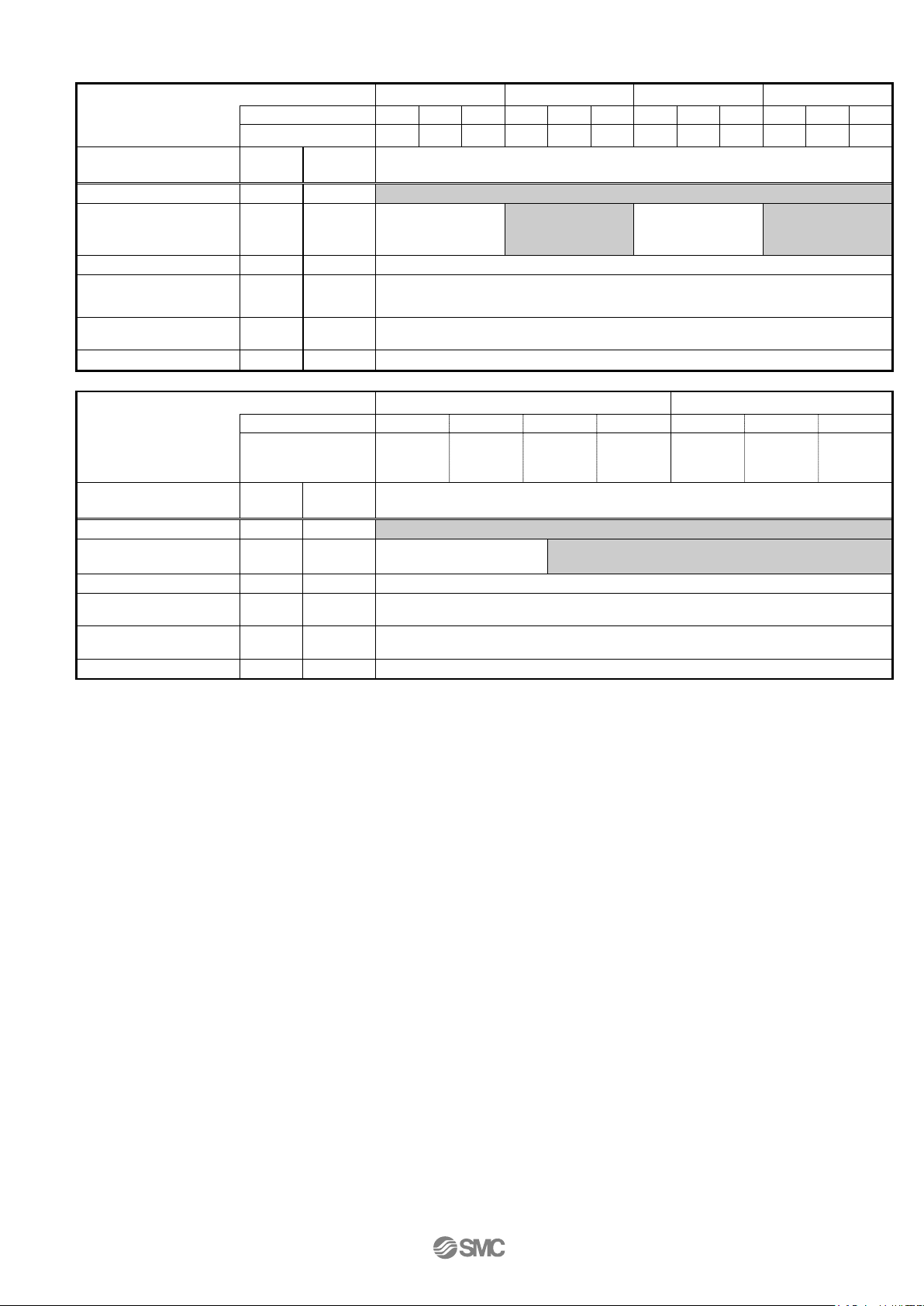
[LECSB]
Series
Lead symbol A B C A B C A B C A B C
Lead
LEY25/LEYG25 LEY25D/LEYG25D LEY32/LEYG32 LEY32D/LEYG32D
12 6 3 12 6 3 20 10 5 16 8 4
Parameter
command input
pulses per
Rotation direction
selection
Series
Para. No
PA05 0 0
PA06 1 32768
PA07 1
(
PA14
PB06 7 7
PB13 4500 4500
PB14 0000 0000
Lead symbol A B C L A B C
0
Lead 20 10 5
+:Counter
75
65536
75
Recommended value
32768
(+:Counter
75
65536
75
(Pulley
32768
(
+:Counter
65536
125 200 100 50
20 10 5
(+:Counter
32768
Parameter
command input
pulses per
Para. No
PA05 0
PA06 1 32768 65536 114688 32768 65536
PA07 1
PA14 0
PB06 7 7
PB13 4500 4500
PB14 0000 0000
250 125 125 125 250 125 125
Recommended value
0
*1 Parameter is the reco mmende d v alue. P lease c h ange the p ara meter to ma ke appr opri ate v alue for y our
operating method.
*2 A mechanical resonance may occur depend ing on the configuration or the mo unt ing orientation of the
transferred object. Plea se change the parameter i n the initial setting.
*3 The travel distance of the actuator per 1 pul s e should be 10 [μm/pulse].
-9-
[LECSC]
LEY25/LEYG25
LEY25D/ EYG25D
LEY32/LEYG32
LEY32D/ EYG32D
Lead symbol
A B C A B C A B C A B
C
Lead
12 6 3
12 6 3
20
10 5 16 8 4
Parameter
Para. No
Initial value
Recommended value
Electronic gear numerator *3
PA06
1
32768
Electronic gear enominator *3
PA07
1
1500
750
375
1500
750
375
2500
1250
625
2000
1000
500
Feel length multiplication
(STM) (Multiplier)
Home position return type
PC02
0000
□□□3 (Stopper type)
Home position return direction
PC03
0001
□□□1 (Motor side)
Home position return Speed (rpm)
PC04
500
150
300
600
150
300
600
90
180
360
112
225
450
Home position return p osition
data (μm)
Stopper type home posi tion
return stop per time (ms ec)
Stopper type home posi tion
return tor qu e limit value (%)
Regenerative option
PA02
0000
0000 (Non)/ 0002 (LEC-MR-RB032)
0
(+:Counter motors side)
1
(+:Counter motors side )
0
(+:Counter motors side)
1
(+:Counter motors side )
Adaptive t uning mode
PB01
0000
0000
Load to motor inertia moment ratio
PB06
7
7
Machine resonance suppression filter 1
PB13
4500
4500
Notch shape selecti on 1
PB14
0000
0000
LEY63
LEY63D
Lead symbol
A B C L A B C
5(2.86)
raito 4/7)
Parameter
Para. No
Initial value
Recommended value
Electronic gear numerator *3
PA06
1
32768
57344
32768
Electronic gear enominator *3
PA07
1
2500
1250
625
625
2500
1250
625
(STM) (Multiplier)
Home position return type
PC02
0000
□□□3 (Stopper type)
Home position return direction
PC03
0001
□□□1 (Motor side)
Home position return speed (rpm)
PC04
500
90
180
360
629
90
180
360
Home position return p osition
data (μm)
Stopper type home posi tion
return stop per time (ms ec)
Stopper type home posi tion
return tor qu e limit value (%)
Regenerative option
PA02
0000
0000 (Non)/ 0002 (LEC-MR-RB032)/ 0003 (LEC-MR-RB12)
0
(
+:Counter motors side)
1
(+:Counter motors side )
Adaptive t uning mode
PB01
0000
0000
Load to motor inertia moment ratio
PB06
7
7
Machine resonance suppression filter 1
PB13
4500
4500
Notch shape selecti on 1
PB14
0000
0000
Series
PA05 0000 0000 (Less than stroke 1000) / 0001 (Stroke 1000 or more)
PC07 0 -2000(Less than stroke 1000) / -200 (Stroke 1000 or more)
PC09 100 200
PC10 15 30
Rotation di rection sel ection
Series
Feel length multiplication
PA14 0
Lead
PA05 0000 0000 (Less than stroke 1000) / 0001 (Stroke 1000 or more)
PC07 0 -4000(Less than stroke 1000) / -400 (Stroke 1000 or more)
PC09 100 200
PC10 15 30
20 10 5
(Pulley
20 10 5
Rotation di rection sel ection
*1 Parameter is the reco mmende d v alue. P lease c h ange the par am eter t o ma ke appr opri ate v alue for y our
operating method.
*2 A mechanical resonance may occur depend ing on the configuration or the mo unt ing orientation of the
transferred object. Plea se change the parameter i n the initial setting.
*3 The minimum unit o f t he travel distance of the actuator should be 1 [μm].
PA14 0
-10-
Lead symbol
A B C A B C A B C A B
C
Lead
12 6 3
12 6 3
20
10 5 16 8 4
Para.
No
Initial
value
Regenerative option
PA02
0000
0000 (Non)/ 0002 (LEC-MR-RB032)
0
motors side)
1
motors side )
0
motors side)
1
motors side )
Adaptive tuning mode
PB01
0000
0000
Machine resonance
suppression filter 1
Notch shape selection 1
PB14
0000
0000
LEY63
LEY63D
Lead symbol
A B C L A B C
5(2.86)
raito 4/7)
Para.
No
Initial
value
Regenerative option
PA02
0000
0000 (Non)/ 0002 (LEC-MR-RB032)/ 0003 (LEC-MR-RB12)
Rotation direction
selection
0
(
+:Counter motors side)
1
(+:Counter motors side )
Adaptive tuning mode
PB01
0000
0000
Load to motor inertia
moment ratio
Machine resonance
suppression filter 1
Notch shape selection 1
PB14
0000
0000
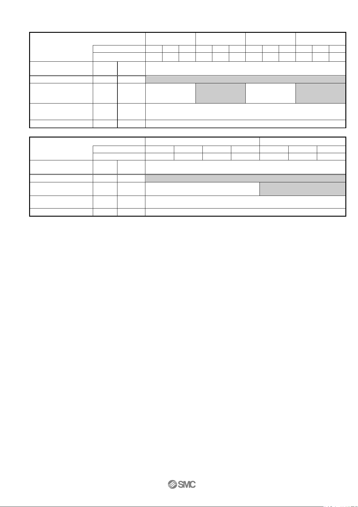
[LECSS]
Series
LEY25/LEYG25 LEY25D/LEYG25D LEY32/LEYG32 LEY32D/LEYG32D
Parameter
Rotation direction
selection
Load to motor inertia
moment ratio
Series
Parameter
Recommended value
(
PA14
PB06
PB13 4500 4500
PA14 0
PB06 7 7
0
7 7
Lead 20 10 5
+:Counter
(+:Counter
(Pulley
Recommended value
(
+:Counter
20 10 5
(+:Counter
PB13 4500 4500
*1 Parameter is the reco mme nded value. P leas e ch ange t he p ara met er to m ake appr opriat e value for y our
operating method.
*2 A mechanical resonance may occur depend ing o n t he c onfiguration or the mounting or ientation of the
transferred object. Plea se change the parameter i n the initial setting.
* For LECSS, please set the el ect r onic gear with PC, PLC etc. in y our application.
-11-
LEY25T6
/ LEYG25T6
LEY25DT6
/ LEYG25DT6
LEY32T7
/ LEYG32T7
LEY32DT7
/ LEYG32DT7
Lead symbol
A B C A B C A B C A B
C
Lead
12 6 3
12 6 3
20
10 5 16 8 4
Para.
No
Initial
value
Regenerative option
PA02
0000
0000 (Non)/ 0002 (LEC-MR-RB-032)
0
motors side)
1
motors side )
0
motors side)
1
motors side )
Function selection E-3
PE41
0000
0000
LEY63T8
LEY63DT8
Lead symbol
A B C L A B C
Lead
20
10 5 2.86
20
10
5
Para.
No
Initial
value
Regenerative option
PA02
0000
0000 (Non)/ 0002 (LEC-MR-RB-032)/ 0003 (LEC-MR-RB-12)
Rotation direction
selection
0
(
+:Counter motors side)
1
(+:Counter motors side )
Load to motor inertia
moment ratio
Function selection E-3
PE41
0000
0000
[LECSS-T]
Series
Parameter
Rotation direction
selection
Load to motor inertia
moment ratio
PA14
PB06
(
0
7 7
+:Counter
Recommended value
(+:Counter
(
+:Counter
(+:Counter
Series
Parameter
PA14 0
PB06 7 7
Recommended value
*1 Parameter is the reco mme nded value. P leas e ch ange t he p ara met er to m ake appr opriat e value for y our
operating method.
*2 A mechanical resonanc e may oc cur depending on the configuration or the mounting orientation of the
transferred object. Plea se change the parameter i n the initial setting.
* For LECSS2-T□, please set the electronic gear with PC, PLC etc. in your appl ication.
-12-
LEY63*
(Parallel type)
LEY63D*
(In-line type)
30, 50, 100, 150, 200,
250,300, 350, 400
30, 50, 100, 150, 200,
250,300, 350, 400, 500
30, 50, 100, 150, 200,
250,300, 350, 400, 500
100, 200, 300, 400, 500, 600,
700, 800
Work load
[kg]
Horizontal
Note 2)
18
50
50
30
60
60
30
60
60
40
70
80
200
Vertical
8
16
30 9 19
37
12
24
46
19
38
72
115
Thrust [N]
Note3)
12 to 24%)
(Set value LEY63T :12 to 40%)
Maximum
Speed
Note4)
[mm/s]
Range
to 300
900
450
225
305 to 400
600
300
150
405 to 500
- - -
800
400
200
640
320
160
505 to 600
- - - - - - - - -
800
400
200
605 to 700
- - - - - - - - -
600
300
150
705 to 800
- - - - - - - - -
500
250
125
Pushing speed [mm/s]
Note5)
35 or less
30 or less
30 or less
acceleration/de cel erati on [m m/s2]
5,000
5,000
5,000
3,000
Positioning re peatability [mm]
±0.02[Basic type] / ±0.01[High precision type]
Lost motion[mm]
0.1 or less[Basic type] / 0.05 or less[High precision type]
Lead[mm] (
Including pulley ratio
)
12 6 3
20
10 5 16 8 4
20
10 5 2.86
Impact resistance/vibration
Resistance [m/s2]
Ball screw
and Belt [4:7]
Guide type
Sliding bush (Piston rod part)
Sliding bush (Piston rod part)
Sliding bush (Piston rod part)
Operating temperature range
[℃]
Operating humidity range [%RH]
90 or less(No condensation)
90 or less (No condensation)
90 or less (No conden sation)
Motor output/size
100W/☐40
200W/☐60
400W/☐60
Type of Motor
AC servo motor (100/200VAC
)
AC servo motor (100/200VAC)
AC servo mot or ( 20 0V A C)
[Type of Motor: S2,S3,S4]: Incremental 17bit encoder (Resolution: 131072 p/rev)
[Type of Moto: T6,T7,T8]: Absolute 22bit encoder (Resolution: 4194304 p/rev)
Type
Note7)
No excitation operating type
No excitation operating type
No excitation operating type
Power consumption [W] at 20
℃ Note8)
6.3
7.9
7.9
7.9
Rated voltage [V]
24VDC
0
-10%
24VDC
0
-10%
DC24
0
-10%
DC24
0
-10%
2. Rod type / LEY Series
2.1 Specification
Model
Stroke [mm]
Note1)
(Set value LEY25/32:15 to 30%)
(Set value LEY63
(Set value LEY25T32T
of
stroke
:
15 to 50%)
:
Actuator specification
Note6)
Drive method
LEY25* / LEY25D*
(Parallel / In-line)
65
131
~
127
255
~
~
242
485
LEY32*
(Parallel type)
79
157
~
154
308
~
~
294
588
LEY32D*
(In-line type)
98
192
~
197
~
385
368
~
736
1200 600 300 1000 500 250
156
~
521
1000 500 250
50 / 20 50 / 20 50 / 20
Ball screw and Belt [1:1] / Ball screw
Ball screw and Belt [1.25:1]
Ball screw Ball screw
5 to 40 5 to 40 5 to 40
~
304
1012
~
573
1910
1003
~
3343
70
Encoder
[Type of Moto: S6,S7,S8]: Absolute 18bit encoder (Resolution: 262144 p/rev)
Holding force [N] 131 255 607 607 607 588 197 385 736 313 607 1146 2006
Lock specification
Note 1) The middle stroke other than the above are produced upon receipt of order.
Note 2) The maximum value of the horizontal workload. (An external guide is necessary[Coefficient of friction: 0.1 or less]).
The actual workload will depend on the type of external guide.
Note 3) Thrust setting range when "thrust control" in torque control mode, etc. Set it referring to the thrust conversion graph shown in the
catalog as a guide.
Note 4) The allowable speed changes by the stroke.
Note 5) Allowable impact speed when "impact work" in torque control mode, etc.
Note 6) Impact resistance:
Vibration resistance:
No malfunction occurred when the actuator was tested with a drop tester in both an axial direction and perpendicular direction
to the lead screw. (The test was performed with the actuator in the initial state.)
No malfunction occurred in a test ranging between 45 to 2000 Hz, when the actuator was tested in both an axial direction
and a perpend icular direction to the lead screw. (The test was per f ormed with th e a ctuator in the i ni tial state.)
Note 7) Only when the motor option, "with lock", is selected.
Note 8) For an actuator with lock, add the power consumption for the lock.
-13-
Model
LEY25* (Parallel type)
LEY25D* (In-line mounting type)
Stroke [mm]
30
50
100
150
200
250
300
350
400
30
50
100
150
200
250
300
350
400
Type of Motor
Incremental Enco der
1.31
1.38
1.55
1.81
1.99
2.16
2.34
2.51
2.69
1.34
1.41
1.58
1.84
2.02
2.19
2.37
2.54
2.72
Absolute Enco de r
1.37
1.44
1.61
1.87
2.05
2.22
2.40
2.57
2.75
1.40
1.47
1.64
1.90
2.08
2.25
2.43
2.60
2.78
Model
LEY32* (Parallel type)
LEY32D* (In-line mounting type)
Stroke [mm]
30
50
100
150
200
250
300
350
400
450
500
30
50
100
150
200
250
300
350
400
450
500
Incremental Enco der
2.42
2.53
2.82
3.29
3.57
3.85
4.14
4.42
4.70
4.98
5.26
2.44
2.55
2.84
3.31
3.59
3.87
4.16
4.44
4.72
5.00
5.28
Absolute Enco de r
2.36
2.47
2.76
3.23
3.51
3.79
4.08
4.36
4.64
4.92
5.20
2.38
2.49
2.78
3.25
3.53
3.81
4.10
4.38
4.66
4.94
5.22
Model
LEY63* (Parallel type)
LEY63D* (In-line mounting type)
Stroke [mm]
100
200
300
400
500
600
700
800 100
200
300
400
500
600
700
800
Incremental Enco der
5.4
6.6
8.3
9.4
10.5
12.2
13.4
14.5 5.6
6.7
8.4
9.6
10.7
12.4
13.5
14.7
Absolute Enco de r
5.5
6.7
8.4
9.5
10.6
12.3
13.5
14.6 5.7
6.8
8.5
9.7
10.8
12.5
13.6
14.8
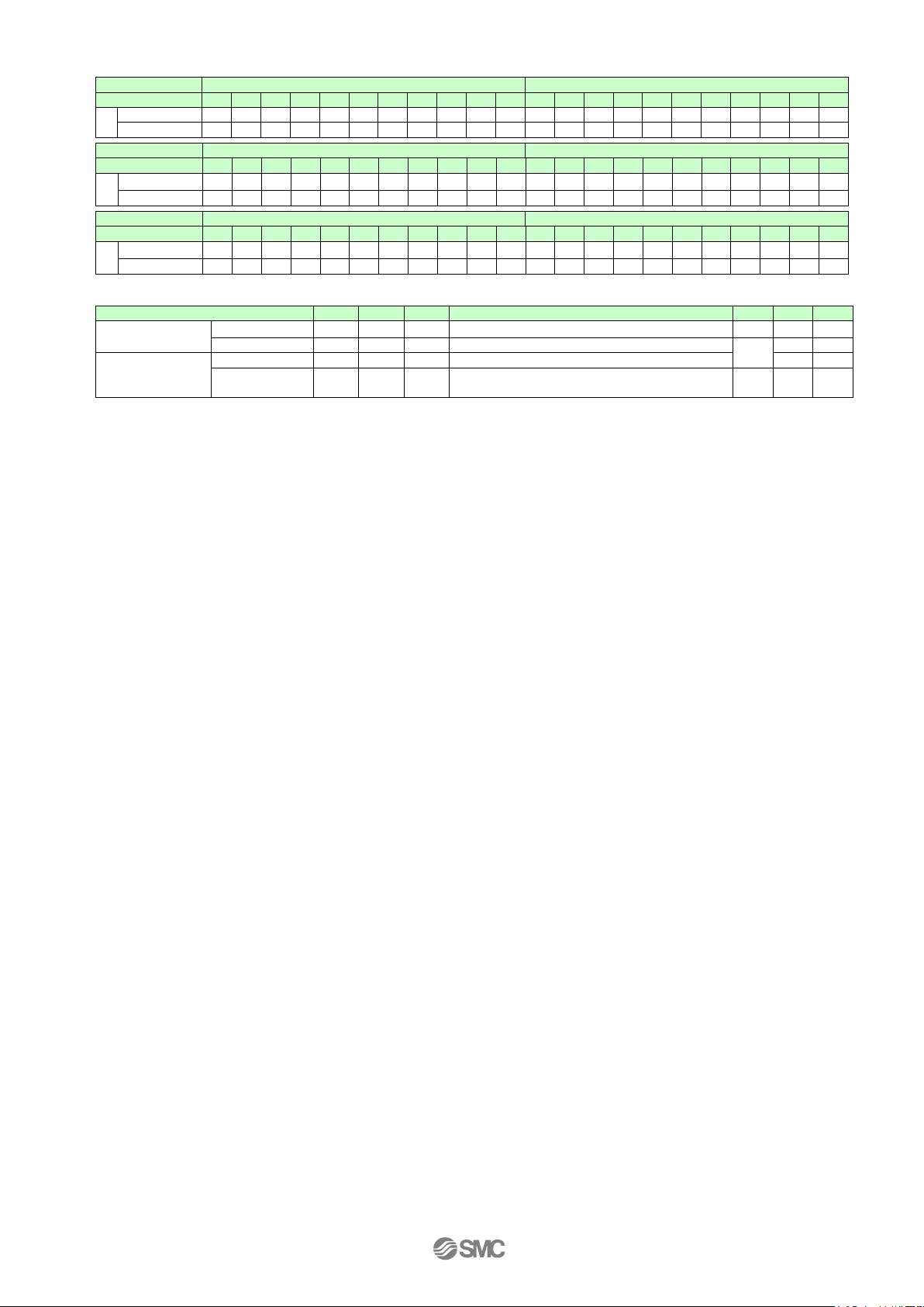
Size
25
32
63
Size
25
32
63
Incremental Encod er
0.20
0.40
0.4
Foot style (Body mounting bolt is included、2sets)
0.08
0.14
0.26
Absolute Encoder
0.30
0.66
0.6
Rod side flange style (Body mounting bolt is included)
0.20
0.51
Rod end male thread
Part of male thread
0.03
0.03
0.12
Motor side fl a nge style (Body mounting bolt isincluded)
-
-
Double clevis style (Clevis pin, Type C retaining ring for axis,
Body mounting bolt is include d)
[kg]
[kg]
[Product Weight]
Type of Motor
Type of Motor
[Additional weight for lock]
Lock
0.17
Nut 0.02 0.02 0.04
0.16 0.22 0.58
-14-
 Loading...