

SMC Networks LEY series Installation And Maintenance Manual
LEY-TF P32-C
Installation and Maintenance Manual
Electric Actuator / Rod Type
Series LEY
Applicable model number:
( -)LEY(S/T/V)-
Note: For special models LEY*-X* please check the appropriate drawing for
the dimensions and specifications.
1 Safety Instructions
This manual contains essential information for the protection of users and
others from possible injury and/or equipment damage.
Read this manual before using the product to ensure correct handling
and also read the manuals of related apparatus before use.
Keep this manual in a saf e place for future reference.
These instructions indicate the level of potential hazard by label of
“Caution”, “Warning” or “Danger”, followed by important safety
information which must be carefully followed.
To ensure safety of personnel and equipment the saf ety instructions in
this manual and the product catalogue must be observed, along with
other relevant safety practices.
Caution
Indicates a hazard with a low level of risk which, if
not avoided, could result in minor or moderate
injury.
Warning
Indicates a hazard with a medium level of risk
which, if not avoided, could result in death or
serious injury.
Danger
Indicates a hazard with a high level of risk which,
if not avoided, w ill result in death or serious
injury.
Electromagnetic compatibility: This product is class A equipment that is
intended for use in an industrial environment. There may be potential
difficulties in ensuring electromagnetic compatibility in other
environments due to conducted as well as radiated disturbances.
Warning
Do not disassemble, modify (including change of printed circuit
board) or repair the product.
An injury or product failure may result.
Do not operate the product beyond the specification range.
Fire, malfunction or equipment damage may result.
Use the product only after confirming the specifications.
Do not use the product in the presence of flammable, explosive or
corrosive gas.
Fire, explosion or corrosion may result.
This product does not have an explosion proof construction.
When using the product as part of an interlocking system:
Provide a double interlocking system, for example a mechanical system.
Check the product regularly to ensure correct operation.
Before performing maintenance, be sure of the following:
Turn off the power supply.
Caution
Always perform a system check after maintenance.
Do not use the product if any error occurs.
Safety cannot be assured if caused by un-intentional malfunction.
Provide grounding to e nsure correct operation and to improve
noise resistance of the product.
This product should be individually grounded using a short cable.
Follow the instructions given below when handling the product.
Failing to do so may result in product damage.
Maintenance space should always be provided around the product.
Do not remove labels from the product.
Do not drop, hit or apply excessive shock to the product.
Unless stated otherwise, follow all specified tightening torques.
Do not bend, apply tensile force, or apply force by placing heavy
loads on the cables.
1 Safety Instructions (continued)
Connect wires and cables correctly and do not connect while the
power is turned on.
Do not route input/output wires and cables together with power or
high-voltage cables.
Check the insulation of wires and cables.
Take appropriate me asures against noise, such as noise filters,
whe n the product is incorporated into other equipment or devices.
Take sufficient shielding measures when the product is to be used
in the following conditions:
• Where noise due to static electricity is generated.
• Where electro-magnetic field strength is high.
• Where radioactivity is present.
• Where power lines are located.
Do not use the product in a place where electrical surges are
gene rated.
Use suitable surge protection when a surge generating load such as
a solenoid valve is to be directly driven.
Prevent any foreign matter from entering this product.
Do not expose the product to vibration or impact.
Use the product within the specified ambient temperature range.
Do not expose the product to any heat radiation.
Use a precision screwdriver with flat blade to adjust the DIP sw itch.
Close the cover over the switches before power is turned on.
Do not clean the product with chemicals such as benzene or
thinners.
2 General Instructions
2.1 Wiring
Warning
Adjusting, mounting or wiring change should not be done before
disconnecting the power supply to the product.
Electrical shock, malfunction and damage can result.
Do not disassemble the cables.
Use only specified cables.
Do not connect or disconnect the wires, cables and connectors
whe n the power is turned on.
Caution
Wire the connector correctly and securely.
Check the connector for polarity and do not apply any voltage to the
terminals other than those specified in the Operation Manual.
Take appropriate measures against noise.
Noise in a signal line may cause malfunction. As a countermeasure
separate the high voltage and low voltage cables, and shorten the wiring
lengths, etc.
Do not route input/output wires and cables together with power or
high voltage cables.
The product can malfunction due to interference of noise and surge
voltage from power and high voltage cables to the signal line. Route the
wires of the product separately from power or high voltage cables.
Take care that actuator movement does not catch cables.
Operate with all wires and cables secured.
Avoid bending cables at sharp angles where they enter the product.
Avoid twisting, folding, rotating or applying an external force to the
cable.
Risk of electric shock, wire breakage, contact failure and loss of control of
the product can happen.
Select “Robotic cables” in case of inflecting cable (encoder/ motor/
rock) repeatedly.
Refer to the “Driver operation manual” for the bending life of the bending
radius of the cable.
2 General Instructions (continued)
Confirm correct insulation of the product.
Poor insulation of w ires, cables, connectors, terminals etc. can cause
interference with other circuits. Also there is the possibility that excessive
voltage or current may be applied to the product causing damage.
2.2 Transportation
Caution
Do not carry or swing the product by the cables.
2.3 Mounting
Warning
Obse rve the tightening torque for screws.
Unless stated otherwise, tighten the screws to the recommended torque
for mounting the product.
Do not make any alterations to this product.
Alterations made to this product may lead to a loss of durability and
damage to the product, which can lead to human injury and damage to
other equipment and machinery.
When an external guide is used, connect the moving parts of the
product and the load in such a way that there is no interference at
any point within the stroke.
Do not scratch or dent the sliding parts of the table or mounting face etc.,
by striking or holding them w ith other objects. The components are
manufactured to precise tolerances, so that even a slight deformation
may cause faulty operation or seizure.
Do not use the product until you verify that the equipment can be
operated correctly.
After mounting or repair, connect the power supply to the product and
perform appropriate functional inspections to check it is mounted
correctly.
When attaching to the work piece, do not apply strong impact or
large moment.
If an external force over the allowable moment is applied, it may cause
looseness in the guide unit, an increase in sliding resistance or other
problems.
Maintenance space
Allow sufficient space for maintenance and inspection.
2.4 Handling
Warning
Do not touch the motor while in operation.
The surface temperature of the motor can increase to approx. 80°C due
to operating conditions.
Energizing alone may also cause this temperature increase.
As it may cause burns, do not touch the motor w hen in operation.
If abnormal heating, smoking or fire, etc. occurs in the product,
imm ediately turn off the power supply.
Immediately stop operation if abnormal operation noise or vibration
occurs.
If abnormal operation noise or vibration occurs, the product may have
been mounted incorrectly. Unless operation of the product is stopped for
inspection, the product can be seriously damaged.
Never touch the rotating part of the motor or the moving part of the
actuator while in operation.
There is a serious risk of injury.
When installing, adjusting, inspecting or performing maintenance
on the product, Driver and related equipment, be sure to turn off the
power supply to each of them. Then, lock it so that no one other
than the person working can turn the power on, or implement
measures such as a safety plug.
Caution
Keep the driver and product combined as delivered for use.
The product is set in parameters for shipment.
If it is combined with a different product parameter, failure can result.
2 General Instructions (continued)
Check the product for the following points before operation.
• Damage to electric driving line and signal lines.
• Looseness of the connector to each power line and signal line.
• Looseness of the actuator/cylinder and driver mounting.
• Abnormal operation.
• Stop function
When more than one person is performing work, decide on the
procedures, signals, measures and resolution for abnormal
conditions before beginning the work.
Also designate a person to supervise the work, other than those
performing the work.
An operation test should be performed at low speed, start the test at
a predefined speed, after confirming there are no problems.
Actual speed of the product will be changed by the workload.
Before selecting a product, check the catalogue for the instructions
regarding selection and specifications.
Do not apply a load, impact or resistance in addition to a transferred
load during return to origin.
In the case of the return to origin by pushing force, additional force will
cause displacement of the origin position since it is based on detected
motor torque.
Do not remove the nameplate.
2.5 Actuator with lock
Warning
Do not use the lock as a safety lock or a control that requires a
locking force.
The lock used is designed to prevent dropping of work piece.
For vertical mounting, use the product with a lock.
If the product is not equipped with a lock, the product will move and drop
the work piece when the power is removed.
"Measures against drops,” means preventing a work piece from
dropping due to its weight when the product operation is stopped
and the power supply is turned off.
Do not apply an impact load or strong vibration while the lock is
activated.
If an external impact load or strong vibration is applied to the product, the
lock will lose its holding force and damage to the sliding part of the lock or
reduced lifetime can result. The same situation will happen when the
lock slips due to a f orce higher than its holding f orce, as this w ill
accelerate the wear to the lock.
Do not apply liquid, oil or grease to the lock or its surroundings.
When liquid, oil or grease is applied to the sliding part of the lock, its
holding force will be reduced significantly.
Take “measures against drops” and check that s afety is assured
befor e mounting, adjustment and inspection of the product.
If the lock is released with the product mounted vertically, a work piece
can drop due to its weight.
2.6 Please refer to the auto switch references in “Best Pneumatics “
whe n an auto switch is to be used.
2.7 Unpacking
Caution
Check the received product is as ordered.
If a different product is installed from the one ordered, injury or damage
could result.
LEY-TF P32-C
3 Specifications
Model
LEY25
LEY25D
(Paralle l/ In -l ine
)
LEY32
(Parallel type)
LEY32D
(In-line type)
LEY63
(Parallel type)
LEY63D
(In-line type)
Actuator
Stroke [mm]
Note1)
30, 50, 100, 150, 200,
250, 3 0 0 , 350, 400
30, 50, 100, 150, 200,
250, 3 0 0 , 350, 400, 500
30, 50, 1 00, 150 , 200 ,
250 ,300, 350, 400 ,
500
100, 200, 300, 400, 50 0,
600, 700, 800
Work load
[kg]
Horizontal
Note
2)
18
50
50
30
60
60
30
60
60
40
70
80
200
Vertical 8 16
30 9 19
37
12
24
46
19
38
72
115
Pushing f orce [N]
Note3)
65131
127255
242-
485
79157
154308
294588
98197
192385
368736
156521
304101 2
573191 0
100 3334 3
Maximum
Speed
Note4)
[mm/s]
Range
of
stroke
to 30 0
900
450
225
1200
600
300
1000
500
250
1000
500
250
70
305 to
400
600
300
150
405 to
500
- - -
800
400
200
640
320
160
505 to
600
- - - - - - - - -
800
400
200
605 to
700
- - - - - - - - -
600
300
150
705 to
800
- - - - - - - - -
500
250
125
Pushing spee d [mm/s]
Note5)
35 or less
30 or less
30 or less
accelera tion/decele ration [mm/s2]
5,000
5,000
5,000
3,000
Po sit ion ing
rep ea ta bil ity
[mm]
Basic type
±0.02
High pre cision type
±0.01
Lost motion
[mm]
Note9)
Basic type
0.1 or less
High pre cision type
0.05 or less
Lea d[mm] (Includ ing p ulley r atio)
12 6 3
20
10 5 16 8 4
20
10 5 2.86
Impact resistance/vibration
Resistance [m/s2]
Note6)
50 / 20
50 / 20
50 / 20
Drive method
Ball screw and B elt [ 1:1]
/ Ball screw
Ball screw a nd Belt
[1.25:1]
Ball s crew
Ball screw a nd Belt [1:1]
/ Ball screw
Ball screw
and B elt
[4:7]
Guide type
Slidin g bus h (Pisto n r od
part )
Slidi ng bush (Pis ton rod part)
Sliding bush (Piston r od pa rt)
Ope rating tempe ratur e r ang e [℃]
5 to 40
5 to 40
5 to 40
Ope rating hu midity ran ge [%RH]
90 or less(No
conde nsation)
90 or less (No condensation )
90 or less ( No con densatio n)
Electrical
Motor output/size
100W/☐40
200W/☐60
400W/☐60
Type of Motor
AC servo motor
Lock
Type
Note7)
No excitation ope rating type
Holding force [N]
131
255
485
157
308
588
197
385
736
313
607
1146
2006
Power cons u m p t io n [W] at 20 ℃
Note8)
LEY(S/T )/LEYV
6.3 / 5.5
7.9 / 6
7.9 / 6
7.9 / 6
Rated voltage
24 VDC
0
-10%
Product Weight [kg]
Model
LEY25 (Parallel type)
LEY25D (In-line mounting type)
Stroke [mm]
30
50
100
150
200
250
300
350
400
30
50
100
150
200
250
300
350
400
Type of Motor
Incremen tal
Encode r[S2 ]
1.3
1.4
1.6
1.8
2.0
2.2
2.3
2.5
2.7
1.3
1.4
1.6
1.8
2.0
2.2
2.4
2.5
2.7
Absolute
Encode r[S6 ]
1.4
1.5
1.6
1.9
2.1
2.2
2.4
2.6
2.8
1.4
1.5
1.6
1.9
2.1
2.3
2.4
2.6
2.8
Absolute
Encode r[T6 ]
1.4
1.5
1.6
1.9
2.1
2.2
2.4
2.6
2.7
1.4
1.5
1.6
1.9
2.1
2.3
2.4
2.6
2.8
Absolute
Encode r[V6 ]
1.2
1.3
1.6
1.7
1.9
2.1
2.2
2.4
2.6
1.2
1.3
1.6
1.7
1.9
2.1
2.3
2.4
2.6
Model
LEY32 (Parallel type)
LEY32D (In-line mounting type)
Stroke [mm]
30
50
100
150
200
250
300
350
400
450
500
30
50
100
150
200
250
300
350
400
450
500
Type of Motor
Incremen tal
Encode r[S3 ]
2.4
2.5
2.8
3.3
3.6
3.9
4.1
4.4
4.7
5.0
5.3
2.4
2.6
2.8
3.3
3.6
3.9
4.2
4.4
4.7
5.0
5.3
Absolute
Encode r[S7 ]
2.4
2.5
2.8
3.2
3.5
3.8
4.1
4.4
4.6
4.9
5.2
2.4
2.5
2.8
3.3
3.5
3.8
4.1
4.4
4.7
5.0
5.2
Absolute
Encode r[T7 ]
2.3
2.4
2.7
3.2
3.5
3.8
4.1
4.3
4.6
4.9
5.2
2.4
2.5
2.8
3.2
3.5
3.8
4.1
4.4
4.6
4.9
5.2
Absolute
Encode r[V7 ]
2.3
2.4
2.7
3.2
3.5
3.8
4.0
4.3
4.6
4.9
5.2
2.3
2.4
2.7
3.2
3.5
3.8
4.1
4.3
4.6
4.9
5.2
Model
LEY63 (Parallel type)
LEY63D (In-line mounting type)
Stroke [mm]
100
200
300
400
500
600
700
800
100
200
300
400
500
600
700
800
Type of Motor
Incremen tal
Encode r[S4 ]
5.4
6.6
8.3
9.4
10.5
12.2
13.4
14.5
5.6
6.7
8.4
9.6
10.7
12.4
13.5
14.7
Absolute
Encode r[S8 ]
5.5
6.7
8.4
9.5
10.6
12.3
13.5
14.6
5.7
6.8
8.5
9.7
10.8
12.5
13.6
14.8
Absolute
Encode r[T8 ]
5.4
6.6
8.3
9.4
10.5
12.2
13.4
14.5
5.6
6.7
8.4
9.6
10.7
12.4
13.5
14.7
Absolute
Encode r[V8 ]
5.3
6.5
8.2
9.3
10.4
12.1
13.3
14.4
5.5
6.6
8.3
9.5
10.6
12.3
13.4
14.6
Additional weight f or lock access ories [kg]
Note 1) Strok es other than the abov e are produced as a special order.
Note 2) The maximum value of the horizontal workload. (An ex ternal guide is
necessary ). The act ual workload will depend on the type of external guide.
Note 3) Thrust setting range when "pushing" operation in torque control mode, etc.
Ref er to the thrust conv ersion graph shown in the catalogue as a guide.
Set v alue LEY25 S/32 S:15 to 30% Set v alue LEY63 T:12 to 40%
Set v alue LEY25 T/32 T:12 to 24% Set value LEY63T:12 to 40%
Set v alue LEY25 V/32 V:45 to 90% Set v alue LEY63 V:45 to150%
Set v alue LEY63 S:15 to 50%
3 Specifications (continued)
Note 4) The allowable speed will be af f ected by the stroke length.
Note 5) Allowable impac t speed when "pushing" operat ion in torque control mode, etc.
Note 6) Im pact resistance: No malf unction occurred when the actuator was tested with a
drop test er in both an ax ial direction and perpendicular
direction t o the lead sc rew. (The test was performed with the
actuator in t he initial state.)
Vibration resis tance: No malf unct ion occurred in a test ranging between 45 to
2000 Hz, when the actuator was tested in both an axial
direction and a perpendicular direction to the lead screw.
(The tes t was performed with the actuator in the initial
state. )
Note 7) Only when the motor option, "with lock", is selected.
Note 8) For an actuat or with lock, add the power consumption f or the lock .
Note 9) A ref erence v alue for correc ting an error in reciprocal operation.
4 Installation
4.1 Design and selection
Warning
Do not apply a load in excess of the actuator specification.
A product should be selected based on the maximum work load and
allowable moment.
If the product is used outside of the operating specification, the eccentric
load applied to the guide will become excessive and have adverse effects
such as creating play in the guide, reduced accuracy and reduced
product life.
Do not exceed the speed limit of the actuator specification.
Select a suitable actuator by the relationship of allowable work load
and speed.
Noise or reduction of accuracy may occur if the actuator is operated in
excess of its specification and could lead to reduced accuracy and
reduced product file.
Do not use the product in applications where excessive external
force or impact force is applied to it.
This can lead to premature failure of the product.
4.2 Handling
Caution
Do not operate by fixing the piston rod and moving the actuator
body.
An excessive load will be applied to the piston rod, leading to damage to
the actuator and reduced lifetime.
Avoid using the electric actuator in a way that rotational torque
would be applied to the piston rod.
If rotational torque is applied to the piston rod the non-rotating guide will
become damaged or deformed and non-rotational accuracy will be
reduced. (Refer to the allowable rotational torque table below)
Allowable
Rotational torque
(Nm or less)
LEY25
LEY32
LEY63
1.1
1.4
2.8
To attach / screw a bracket or nut to the end of the piston rod.
The piston rod should be fully retracted.
Hold the piston rod by the square across flats end with a spanner or
other means to prevent the piston rod from rotating.
Ensure that the bracket, screw or nut is installed correctly and tightened
to the specified torque value given in this document.
4 Installation (continued)
4.3 Mounting
Caution
When mounting the product, use screws with adequate length and
tighten them to the recommended torque.
Tightening w ith larger torque than the specified range may cause malfunction while the tightening with smaller torque can allow the
displacement of actuator position. In extreme conditions the actuator
could become detached from it’s mounting position.
Work fixed/Rod end female thread
Model
Screw
Max. tightening
torque [Nm]
Max. thread
depth L [mm]
Rod end width
across flats [mm]
LEY25
M8 x 1.25
12.5
13
17
LEY32
M8 x 1.25
12.5
13
22
LEY63
M16 x 2
106
21
36
Work fixed/Rod end male thread
Model
Screw
Max. tightening
torque [Nm]
Max. thread
length L [mm]
Rod end width
across flats [mm]
LEY25
M14 x 1.5
65.0
20.5
17
LEY32
M14 x 1.5
65.0
20.5
22
LEY63
M18 x 1.5
97
26
36
Model
Rod end nut
thread
depth of
bracket[mm]
Width across
flats [mm]
Length
[mm]
LEY25
22 8 14
LEY32
22 8 14
LEY63
27
11
18
Tighten the product mounting screws to the specified torque.
Tightening to a torque over the specified range can cause operation
failure, and insufficient torque can cause displacing or dropping of the
attachment.
Mounting / Screw bottom tapped style
(When “Body bottom tapped” is selected)
Model
Screw
Max. tightening
torque [Nm]
Max. thread
depth L [mm]
LEY25
M5 x 0.8
3.0
6.5
LEY32
M6 x 1. 0
5.2
8.5
LEY63
M8x1.25
12.5
10
Mounting / Rod side - Head side tapped style
Model
Screw
Max.
tightening
torque [Nm]
Max. thread
depth L [mm]
LEY25
M5 x 0.8
3.0
8
LEY32
M6 x 1.0
5.2
10
LEY63
M8 x 1.25
12.5
16
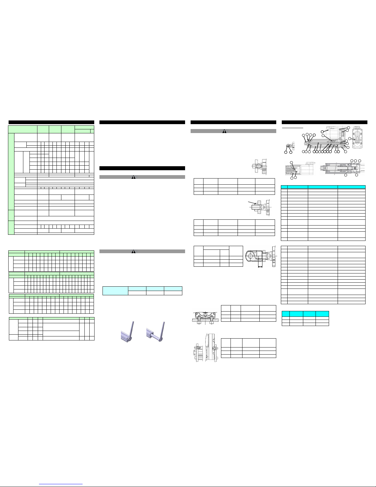
5 Names and Functions of Individual Parts
Parallel motor type
Rod end
male thread
In-line motor type [LEY25/32] In-line motor type [LEY63]
No.
Part
Material
Remarks
1
Body
Aluminium alloy
Anodized 2 Ball screw shaft
Alloy steel 3
Ball screw nut
- 4
Piston
Aluminium alloy
5 Piston rod
Stainless steel
Hard chrom e anodized
6
Rod cover
Aluminium alloy
7 Bearing holder
Aluminium alloy
8 Rotation stopper
POM
9
Socket
Free cutting carbon steels
Nickel plated
10
Connected shaft
Free cutting carbon steels
Nickel plated
11
Bushing
Lead bronze cast
25A-LE Y: St eel bearing all oy
12
Bearing -
13
Pulley box
Aluminium die-cast
Non-Hexavalent chom ated
14
Pulley plate
Aluminium die-cast
Non-Hexavalent
chromated
15
Magnet -
16
Wear ring holder
Stainless steel
Only stroke 101mm or more
17
Wear ring
POM
Only stroke 101mm or more
18
Pulley
(For Screw shaft)
Aluminium alloy
19
Pulley (For motor)
Aluminium alloy
20
Belt -
21
Parallel pin
Stainless steel
22
Rod seal
NBR 23
Retaining ring
Steel for spring
24
Motor adapter
Aluminium alloy
Coating
25
Motor -
26
Motor block
Aluminium alloy
Coating
27
Hub
Aluminium alloy
28
Spider
Urethane
Spider
29
Socket
(male thread)
Free cutting carbon steels
Nickel plated
30
Nut
Alloy steel 31
Lock-nut
Alloy steel
32
Spacer-A
Stainless steel
Mounting bracket part number
Size
Foot
Flange
Double
clev is
25
LEY-L025
LEY-F025
LEY-D025
32
LEY-L032
LEY-F032
LEY-D032
63
LEY-L063
LEY-F063
LEY-D063
• When o rdering fo ot bracke t, order 2 pieces per
actuator .
• Pa rts belonging to each bracket are as fol lows.
Foot, Flange: Body m ounti ng bol t.
Double clevis: Clevis pin, Type C retaining ri ng for
axis, Body mounti ng bolt
Size
25
32
63
Size
25
32
63
Lock
Increment al Encode
[Sr2/S 3/S 4]
0.2
0.4
0.4
Foot style ( Body mo unting screw is in cluded、2sets)
0.08
0.14
0.26
Abso lu t e E ncod er
[S 6/S 7/ S 8 ]
0.3
0.7
0.6
Rod sid e flang e style ( Body moun ting screw is in cluded )
0.17
0.20
0.51
Abso lu t e E ncod er
[T6/T7 / T 8]
0.3
0.4
0.4
Abso lu t e E ncod er
[V 6/V 7/ V 8 ]
0.3
0.6
0.6
Motor side flange style (Bo dy mou nting screw is in cluded)
Rod end male
thread
Part of male threa d
0.03
0.03
0.12
Nut
0.02
0.02
0.04
Double c levis st yle ( Clevi s pin , T ype C reta in ing rin g for axis ,
Body mo unting bo lt is includ ed)
0.16
0.22
0.58
X
Rod end nut
Thread depth
of bracket
\/
10
14
20
17
16
9
23
22
11
21
25
6 1 2 5 13
12 7 8 3 15
4
18
11
1 2 5 8 3 4 7
19
24
26
26
28
27
30
29
7
24
31
32
 Loading...