

SMC Networks LEYG,LEY Operation Manual
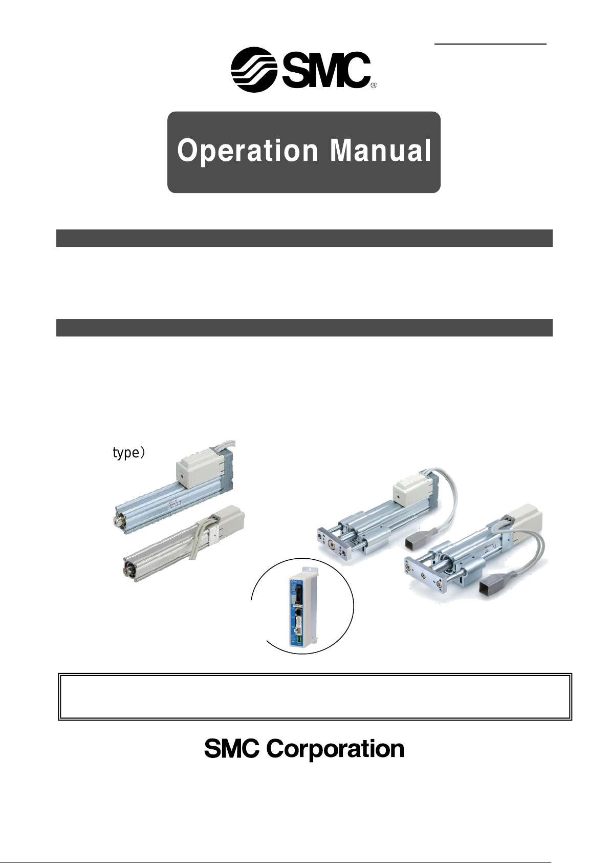
This manual describes the actuators operation in combination with the LEC*6 series controllers.
Doc. no. LEY-OM00211
LEY Series
Rod type)
LEYG Series
Guide Rod type)
<Controller>
LEC Series
PRODUCT NAME
Electric Actuator / Rod Type
MODEL / Series / Product Number
LEY Series
Applicable models: LEY[], LEYG[],
(
(
Refer to the manual relevant to the controller being used for full operating instructions.

Contents
Safety Instructions ............................................................................. 2
1. Procedure before operation/simple setting to use straight awa y4
1.1 Preparation ................................................................................ 4
1.2 Controller setting software version ......................................... 5
1.3 T eaching box ............................................................................. 7
2. Rod type / LEY Series .................................................................... 9
2.1 Specification .............................................................................. 9
2.2 How to Order ............................................................................ 11
2.3 Construction............................................................................ 12
3. Guide rod type / LEYG Series ..................................................... 13
3.1 Specification ............................................................................ 13
3.2 How to Order ........................................................................... 15
3.3 Construction............................................................................ 16
4. Product Outline ............................................................................ 17
4.1 System construction .............................................................. 17
4.2 Setting Function ...................................................................... 18
4.3 Step data setting method ....................................................... 21
4.4 Parameter setting .................................................................... 32
5. Wiring of cables / Common precautions .................................... 35
6. Electric actuators / Common precautions ................................. 36
6.1 Design and selection .............................................................. 36
6.2 Mounting .................................................................................. 37
6.3 Handling .................................................................................. 38
6.4 Operating environment .......................................................... 39
6.5 Maintenance ............................................................................ 40
6.6 Precautions for actuator with lock ........................................ 40
7. Electric actuators / Common precautions ................................. 41
7.1 Design and selection .............................................................. 41
7.2 Handling .................................................................................. 41
7.3 Mounting .................................................................................. 45
7.4 Precaution on maintenance ................................................... 47
8. Troubleshooting ........................................................................... 48
- 1 –
LEY Series / Electric Rod type
Caution
Danger
Warning
Safety Instructions
These safety instructions are intended to prevent hazardous situations and /or equipment damage.
These instructions indicate the level of potential hazard with the labels of “Caution,” “Warning” or “Danger.”
They are all important notes for safety and must be followed in addition to International Standards (ISO
/IEC), Japan Industrial Standards (JIS)*1) and other safety regulations*2).
*1) ISO 4414: Pneumatic fluid power -- General rules relating to systems
ISO 4413: Hydraulic fluid power -- General rules relating to systems
IEC 60204-1: Safety of machinery -- Electrical equipment of machines (Part 1: General requirements)
ISO 10218-1992: Manipulating industrial robots -- Safety
JIS B 8370: General rules for pneumatic equipment.
JIS B 8361: General rules for hydraulic equipment.
JIS B 9960-1: Safety of machinery – Electrical equipment for machines. (Part 1: General requirements)
JIS B 8433-1993: Manipulating industrial robots - Safety. etc.
*2) Labor Safety and Sanitation Law, etc.
Caution
Warning
moderate injury.
Warning indicates a hazard with a medium level of risk which, if not avoided, could result in
death or serious injury.
Danger indicates a hazard with a high level of risk which, if not avoided, will result in death or
serious injury.
indicates a hazard with a low level of risk which, if not avoided, could result in minor or
1. The compatibility of the product is the responsibility of the person who designs the equipment or
decides its specifications.
Since the product specified here is used under various operating conditions, its compatibility with specific
equipment must be decided by the person who designs the equipment or decides its specifications based on
necessary analysis and test results.
The expected performance and safety assurance of the equipment will be the responsibility of the person who
has determined its compatibility with the product.
This person should also continuously review all specifications of the product referring to its latest catalog
information, with a view to giving due consideration to any possibility of equipment failure when configuring the
equipment.
2. Only personnel with appropriate training should operate machinery and equipment.
The product specified here may become unsafe if handled incorrectly.
The assembly, operation and maintenance of machines or equipment including our products must be
performed by an operator who is appropriately trained and experienced.
3. Do not service or attempt to remove product and machinery /equipment until safety is confirmed.
The inspection and maintenance of machinery /equipment should only be performed after measures to
prevent falling or runaway of the
When the product is to be removed, confirm that the safety measures as mentioned above are implemented
and the power from any appropriate source is cut, and read and understand the specific product precautions
of all relevant products carefully.
Before machinery /equipment is restarted, take measures to prevent unexpected operation and malfunction.
4. Contact SMC beforehand and take special consideration of safety measures if the product is to
be used in any of the following conditions.
1) Conditions and environments outside of the given specifications, or use outdoors or in a place exposed to
direct sunlight.
2) Installation on equipment in conjunction with atomic energy, railways, air navigation, space, shipping,
vehicles, military, medical treatment, combustion and recreation, or equipment in contact with food and
beverages, emergency stop circuits, clutch and brake circuits in press applications, safety equipment or other
applications unsuitable for the standard specifications described in the product catalog.
3) An application which could have negative effects on people, property, or animals requiring special safety
analysis.
4) Use in an interlock circuit, which requires the provision of double interlock for possible failure by using a
mechanical protective function, and periodical checks to
driven objects have been confirmed.
confirm proper operation.
- 2 -
Caution
If anything is unclear, contact your nearest sales branch.
due to the deterioration of rubber material are not covered by the limited warranty.
LEY Series / Electric Rod type
Safety Instructions
The product is provided for use in manufacturing industries.
The product herein described is basically provided for peaceful use in manufacturing industries.
If considering using the product in other industries, consult SMC beforehand and exchange specifications
or a contract if necessary.
Limited warranty and Disclaimer /Compliance Requirements
The product used is subject to the following “Limited warranty and Disclaimer” and “Compliance
Requirements”.
Read and accept them before using the product.
Limited warranty and Disclaimer
The warranty period of the product is 1 year in service or 1.5 years after the product is delivered.*3)
Also, the product may have specified durability, running distance or replacement parts. Please
consult your nearest sales branch.
For any failure or damage reported within the warranty period which is clearly our responsibility, a
replacement product or necessary parts will be provided.
This limited warranty applies only to our product independently, and not to any other damage
incurred due to the failure of the product.
Prior to using SMC products, please read and understand the warranty terms and disclaimers noted
in the specified catalog for the particular products.
*3)
Vacuum pads are excluded from this 1 year warranty.
A vacuum pad is a consumable part, so it is warranted for a year after it is delivered.
Also, even within the warranty period, the wear of a product due to the use of the vacuum pad or failure
Compliance Requirements
When the product is exported, strictly follow the laws required by the Ministry of Economy, Trade and
Industry (Foreign Exchange and Foreign Trade Control Law).
- 3 -
(2) Controller
(3) Power supply plug
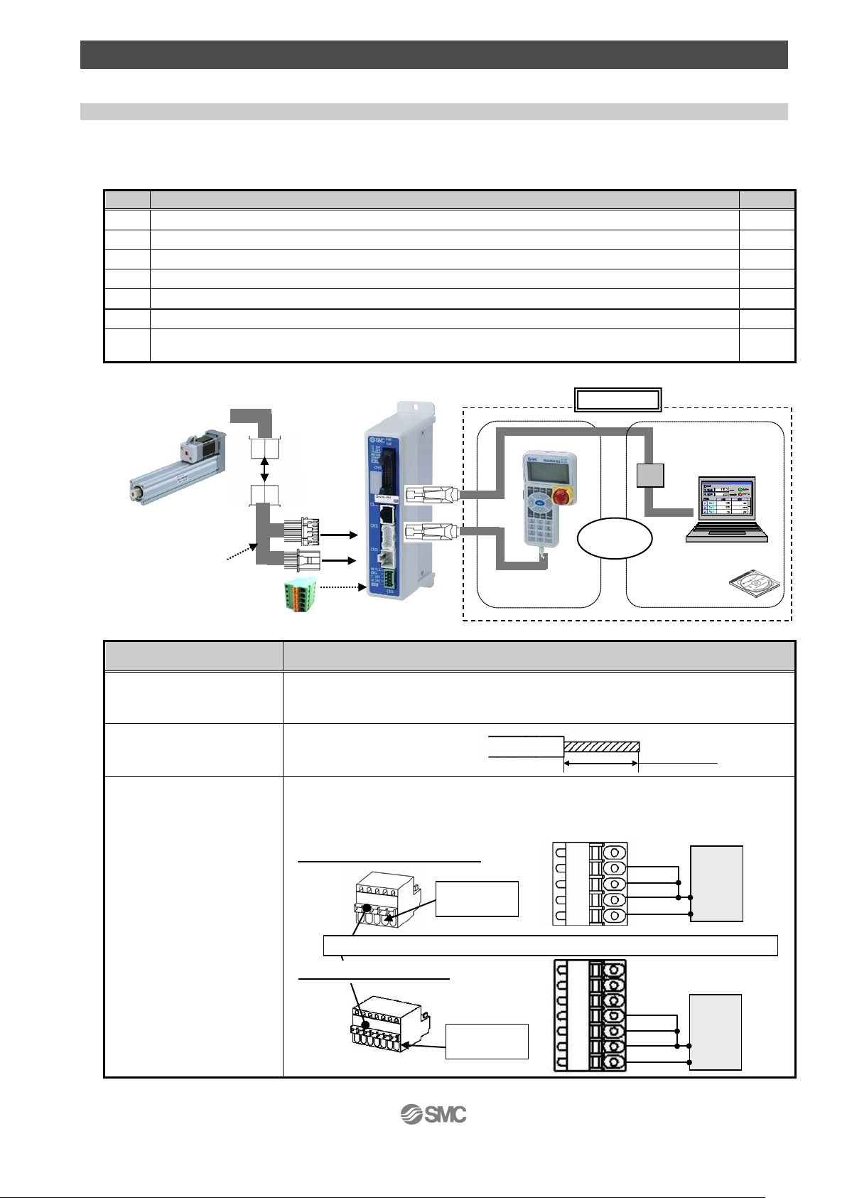
1. Procedure before opera t ion/simple setting to use straight away
No.
Part name
Qty
(1)
Electric actuator / Rod type
1
(2)
Controller
1
(3)
Power supply plug
1
(4)
Actuator cable
1
(5)
I/O cable (Not use in this sect io n)
1
(6)
Teaching box
1
Controller setting kit
[The controller setting software, The communication cable, USB cable and conversion unit are included.]
Power supply 24VDC
Refer to power consumpti on of each actuator
(Prepare the power supply that has capacity of “Moment max.pow e r consumption” or more.)
Connect the plus side of 24VDC to the C24V, M24V and EMG terminal s of
conformity to UL is required, the electric actuator and controller should be used with a
Stripped w ire length
8mm
Electrical
Step motor (servo 24VDC)
Servo motor (24VDC)
Push the open/clese lever and insert the wire into the electrical wire entry
EMG
24VDC
0V
0V
M24V
C24V
Electrical
EMG
24VDC
0V
0V
M24V
C24V
Option
(7) Controller
Setting kit
Communication
PC
To USB port
(6) T eaching box
or
(1) Electric actuator
(4) Actuator cable
To CN3
To CN2
To CN4
The controller is shipped with the parameters appropriate to the actuat or.
With the simple setting “ easy mode”, it can be operated and running p ar ameters can be changed easily.
1.1 Preparati on
(1) Items to be prepared
Please check on the label, and the quantity of accessories, to confirm that it is the product that was
ordered.
Table 1. Componets
(7)
/Rod type
③電源プラグ
Table 2. Items to be prepared by the customer
Part name Conditions
Do not use the power supply
with “Inruch-restraining type”
/ See 2.1Specification[LEY] on p.9, 3.1 Specification[LEYG] on p.13
Wire AWG20 (0.5mm2)
1
the power supply plug, and the minus side to the 0V terminal. When
UL1310 Class 2 power supply.
Power supply plug
Wiring
wire entry
wire entry
- 4 -
power
suppiy
24V
power
suppiy
24V
Caution
(1)
(1)
(2)
(2)
Extended
Retracted
Extended
1.2 Controller setting so ftware version
1. Installat ion of software
With the controller setting software CD-ROM, install the communication unit software, following the
“Software Installation procedure” (PDF)
2. Start up of software
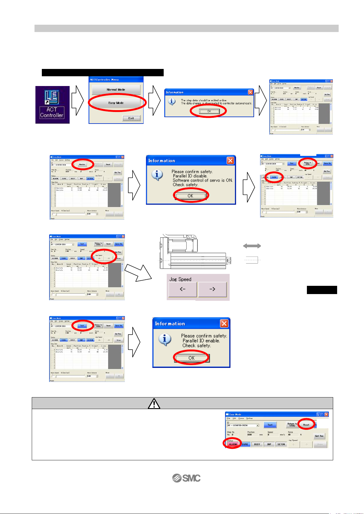
After turning on the controller power supply, start up the ACT Controller setting soft ware
3. JOG Drive
a. Driving preparation: Servo On → Return to ORIG
Select “Monitor” Select “OK” (1)”SVRE” lighting is confirmed
b.JOG Drive (2) Select “Return to ORIG”
c. Driving stop: Servo Off
Select “Test” Select “OK”
Select “Easy Mode” Select “OK”
Clicking arrow button→Operation
If an alarm is generated
(1) When ”ALARM” is generated, release it by selecting (2) Reset.
In the case of an alarm code that c annot be released with
“Reset”, turn the power supply OFF and ON aga in.
Note) For details of alarm codes, refer to the Controller Operati on M anual.
- 5 -
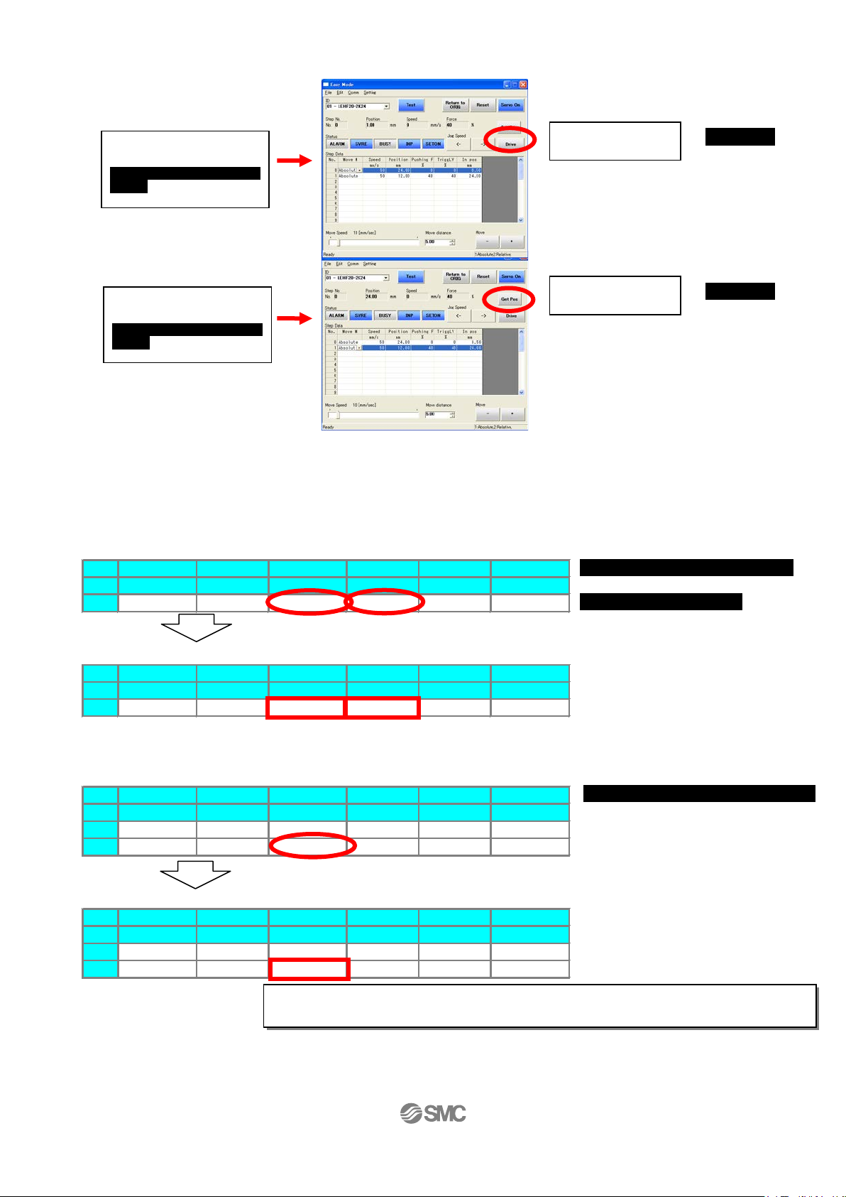
4. TEST Drive / Step No.0 → No.1 → No.0
Step Data
No. Move M Speed Position Pushing F TriggLV In pos
mm/s mm % % mm
0 Absolute 250 50.00 40 40 20.00
Step Data
No. Move M Speed Position Pushing F TriggLV In pos
mm/s mm % % mm
0 Absolute 250 40.00 60 40 20.00
Step Data
No. Move M Speed Position Pushing F TriggLV In pos
mm/s mm % % mm
0 Absolute 250 40.00 60 40 20.00
1 Absolute 250 0.00 0 0 0.50
Step Data
No. Move M Speed Position Pushing F TriggLV In pos
mm/s mm % % mm
0 Absolute 250 40.00 60 40 20.00
1 Absolute 250 20.00 0 0 0.50
Procedure 1:
Procedure 2:
Select “Drive”
Procedure 3:
Procedure 4:
Select “Drive”
For details of operat ion, and relationship between operation procedure and input/
Change of positioning stop position
Input ”60”
Input ”40”
Change of pushing st art position
Input ”20”
・・・
a. Driving preparation: Servo On → Return to ORIG / Refer to “3.JOG Drive”.
b.TEST Drive
“Step No.0” Operation
→ Operation
Select “Step No.0”
You can select anywhere in
the row
“Step No.1” Operation
→ Operation
Select “Step No.1”
You can select anywhere in
the row
c.Driving st o p : Servo Off / Refer to 3.JOG Drive.
5. Step dat a change
Ex) “Step No.0” / Pushing operation / At the time of shipment, Step No.0 is set to pushing operation
Position: 50mm → 40mm
Change of pushing force
Pushing force: 40% → 60%
Ex) “Step No.1” / Positi oning operation / At the t ime of shipment, Step No.1 i s set t o pos iti oning operation
Position: 0mm → 20mm
output signals, refer to “4.3 St ep Dat a sett ing metho d” p. 21 to 29.
6. Controller setting software screen explanation
Refer to the “Help / Easy mode” menu in the “ACT Controller” setting software.
- 6 -
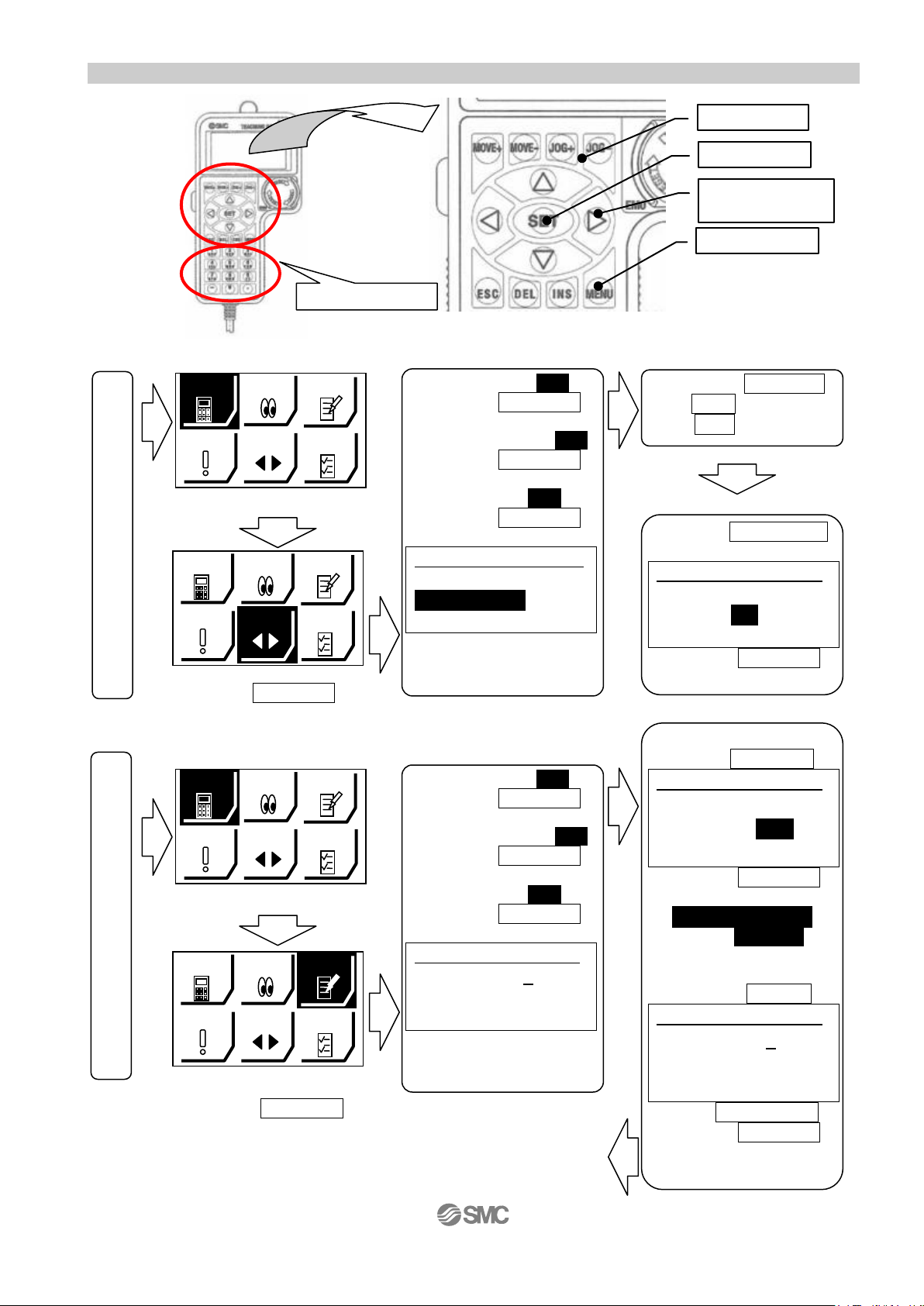
(1) Number key
(4) Up and down,
right and left key
(3)SET key
(2) JOG key
(5)MENU key
アラーム
ジョグ
設定
SETTING
テスト
モニタ
データ
アラーム
ジョグ
SETTING
テスト
モニタ
データ
The power supply is turned on.
EXT Inp OFF:YES
JOG 1
RTN ORIG Done
“JOG±”:Move
Posn 123.45mm
Operates by (2) JOG key
Press the (5)MENU key
Check 1
EXT Inp ON
OK
<1: Drive test >
Test 1
Step No. 0
Test Start
Posn 50.00mm
Test 1
Step No. 1
Test Start
Posn 50.00mm
Repeat <1: Drive test>
AX
IS.
AX
IS.
The power supply is turned on.
アラーム
ジョグ
SETTING
テスト
モニタ
データ
アラーム
ジョグ
SETTING
テスト
モニタ
データ
EXT Inp OFF:YES
Test 1
Step No. 0
Test Start
Posn 50.00mm
1.3 T eaching box
1. Name
2. JOG Drive
Select “JOG” Method of ending “JOG Drive”
3. TEST Drive / Step No.0 → No.1 → No.0
It is the same as the Method
DATA
ALARM
MONITOR
JOG
TEST
Press the (3)SET key
Servo ON,Ready?:YES
Press the (3)SET key
RTN ORIG:Start
Press the (3)SET key
DATA
ALARM
MONITOR
JOG
TEST
設定
Press the (3)SET key
・・・
DATA
ALARM
Select “TEST”
DATA
ALARM
MONITOR
MONITOR
JOG
JOG
TEST
設定
TEST
設定
Press the (3)SET key
Servo ON,Ready?:YES
Press the (3)SET key
RTN ORIG:Start
Press the (3)SET key
Press the (3)SET key
Method of ending “TEST Drive”
of ending “JOG Drive”
- 7 -
↓
↓
↓
↓
↓
↓
JOG+: extract
JOG-: retract
↓
Press the (3)SET key
Press the
(4)Down key
Press the (3)SET key
↓
Step No.0(Open)
Test Complete
<2: Select Step No..>
Press the
Press the (1)Number key”1”
Press the (3)SET key
↓
(4)Up key
↓
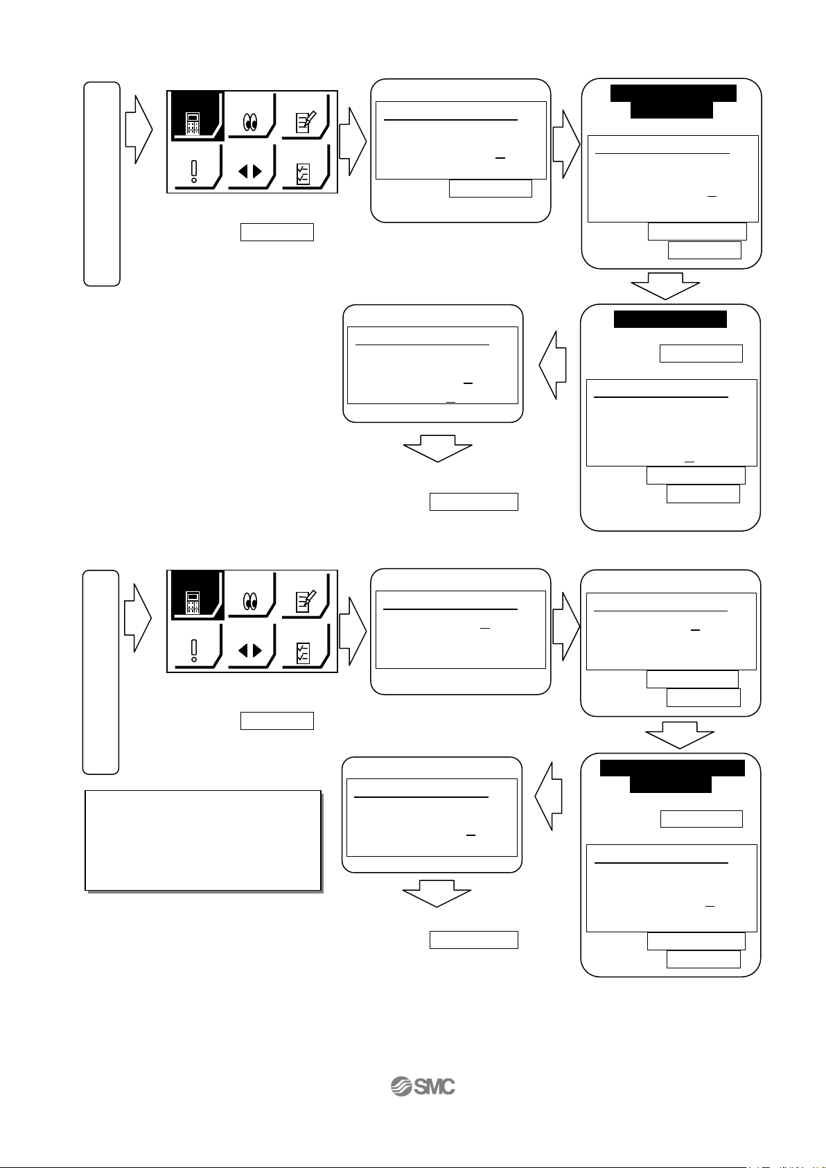
4. Step data change
“Complete”
Step 1
Step No. 1
Posn 20.00mm
Speed 250 mm/s
The power supply is turned on.
アラーム
ジョグ
設定
SETTING
テスト
モニタ
データ
“Step No.0”
Step 1
Step No. 0
Posn 50.00mm
Speed 250 mm/s
Change of pushing
Step 1
Step No. 0
Posn 50.00mm
Speed 250 mm/s
For details of operat ion, and
Change of Speed
Step 1
Step No. 0
Posn 40.00mm
Speed 250 mm/s
“Complete”
Step 1
Step No. 0
Posn 40 .00mm
Speed 250 mm/s
AX
IS.
AX
IS.
AX
AX
IS.
アラーム
ジョグ
SETTING
テスト
モニタ
MONITOR
データ
The power supply is turned on.
“Step No.0”
Step 1
Step No. 0
Posn 40.00mm
Speed 250 mm/s
Change“Ste p No.1”
Step 1
Step No. 0
Posn 40.00mm
Speed 250 mm/s
AX
IS.
AX
IS.
Change of positioning
Step 1
Step No. 1
Posn 0.00mm
Speed 250 mm/s
AX
AX
IS.
“Step No.0” / Pushing operation / At the time of s hipment, Step No.0 is set to pushing operation
DATA
ALARM
Press the (3)SET key
“Step No.1” / Positioning operation / At the time of shipment, Step No.1 is set t o positioning operation
DATA
ALARM
Press the (3)SET key
relationship between operation
procedure and input/ output
signals, refer to “4.3 Step Data
setting method” p. 21 to 29.
5. Teaching box detailed explanation
Please refer to the teaching box manua l.
MONITOR
JOG
Select “DATA”
JOG
Select “DATA”
TEST
Press the (4)Down key
Select “Posn”
Method of ending “DATA”
Press the (5)MENU key
TEST
設定
Select”Step No.”
Method of ending “DATA”
Press the (5)MENU key
- 8 -
start position
Posn 50 mm → 40mm
Press the (1)Number key”40”
Press the (3)SET key
Speed 250 → 100mm/s
Press the (4)Down key
Select “Speed”
IS.
Press the (1)Number key”60”
Press the (3)SET key
Press the (1)Number key”1”
Press the (3)SET key
stop position
Posn 0 mm → 20mm
Press the (4)Down key
Select “Posn”
IS.
Press the (1)Number key”20”
Press the (3)SET key
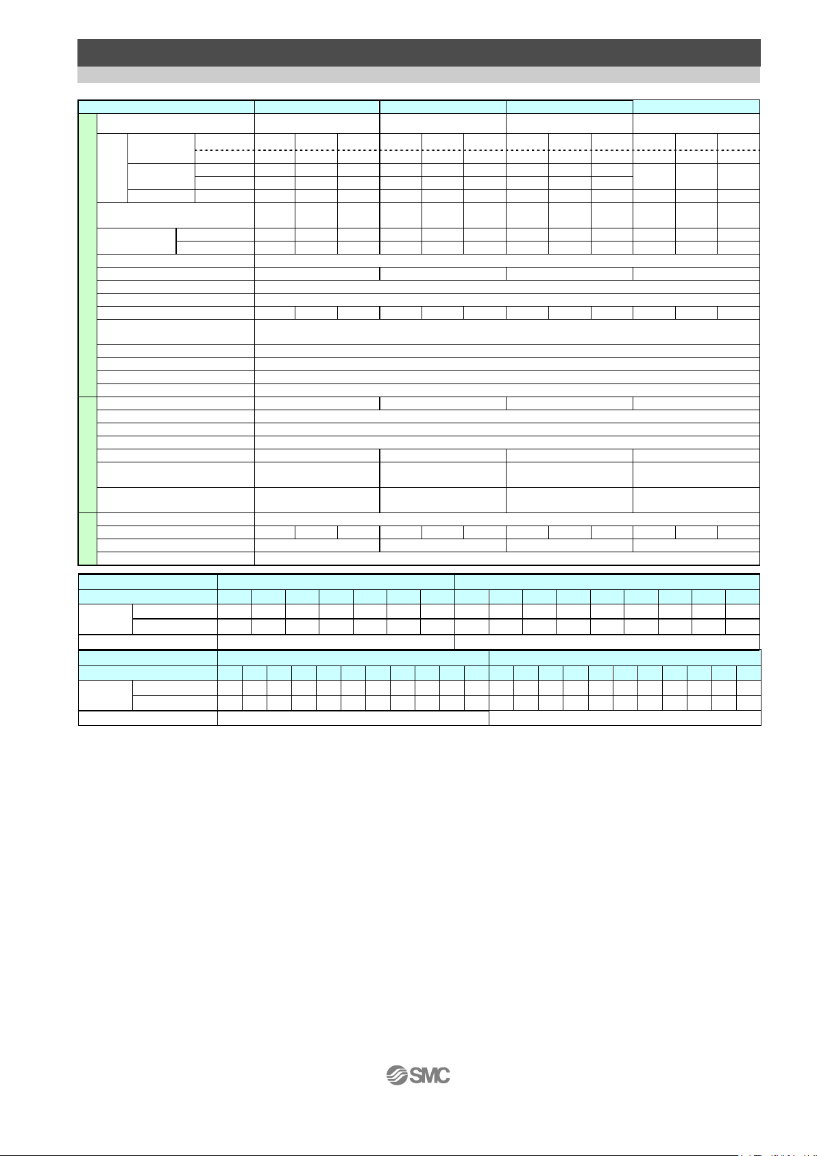
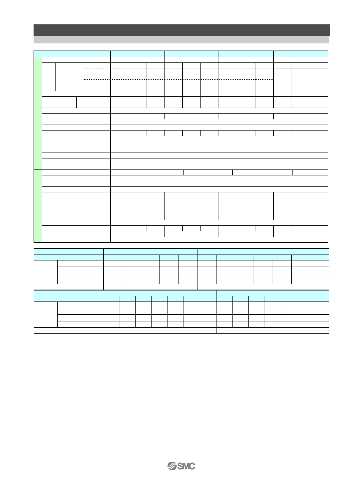
2. Rod type / LEY Series
Model
LEY 16
LEY 25
LEY 32
LEY 40
Note1)
30, 50, 100, 150, 200, 250, 300, 350,
400
30, 50, 100, 150, 200, 250, 300, 350,
400, 450, 500
30, 50, 100, 150, 200, 250, 300, 350,
400, 450, 500
(2000[mm2/s])
10
23
35
30
55
70
40
60
80
60
70
90
(3000[mm2/s])
4
11
20
12
30
30
20
40
40
(2000[mm2/s])
6
17
30
18
50
50
30
60
60
Vertical
(3000[mm2/s])
2 4 8 8 16
30
11
22
43
13
27
53
14
to 38
27
to 74
51
to 141
63
to 122
126
to 238
232
to 452
80
to 189
156
to 370
296
to 707
132
to 283
266
to 553
562
to 1058
Speed [mm/s]
(Contoller type:
LECP6,LECP1,LECPMJ)
15 to 500
8 to 250
4 to 125
18 to 500
9 to 250
5 to 125
15 to 500
8 to 300
4 to 150
24 to 500
12 to 350
6 to 175
15 to 500
8 to 250
4 to 125
18 to 500
9 to 250
5 to 125
15 to 500
8 to 250
4 to 125
24 to 300
12 to 150
6 to 75
acceleration/deceleration
3,000 or less
Pushing speed [mm/s]
Note6)
50 or less
35 or less
30 or less
30 or less
Positioning repeatability [mm]
+/- 0.02
Lost motion[mm]
0.1 or less
Lead [mm]
10 5 2.5
12 6 3
16 8 4
16 8 4
Impact resistance/vibration
Resistance [m/s2]
Drive method
Ball screw and Belt (For “LEY*_ / R / L ”), Ball screw (For “LEY*D)
Guide type
Sliding bush(Piston rod part)
Operating temperature range [℃]
5 to 40
Operating humidity range [%]
90 RH or less(No condensation)
Motor size
□28
□42
□56.4(M)
□56.4(L)
Type of Motor
Step motor (Servo 24VDC)
Encoder
Incremental A/B phase (800 pulse/rotation)
Rated voltage [VDC]
24 +/- 10%
Power consumption [W]
Note8)
23
40
50
50
Standby power consumption
when operating [W]
Moment max. power
Consumption [W]
Lock unit
Rated voltage [VDC]
No excitation operating type
Holding force [N]
20
39
78
78
157
294
108
216
421
127
264
519
Power consumption [W]
Note12)
3.6 5 5
5
Rated voltage [VDC]
24+/-10%
Model
LEY 16
LEY 25
Stroke [mm]
Note1)
30
50
100
150
200
250
300
30
50
100
150
200
250
300
350
400
LEY□[_ /R/L]
0.58
0.62
0.73
0.87
0.98
1.09
1.20
1.18
1.25
1.42
1.68
1.86
2.03
2.21
2.38
2.56
LEY□D
0.58
0.62
0.73
0.87
0.98
1.09
1.20
1.17
1.24
1.41
1.67
1.85
2.02
2.20
2.38
2.55
Additional weight for lock [kg]
0.12
0.26
Model
LEY 32
LEY 40
Stroke [mm]
Note1)
30
50
100
150
200
250
300
350
400
450
500
30
50
100
150
200
250
300
350
400
450
500
[kg]
LEY□[_ /R/L]
2.09
2.20
2.49
2.77
3.17
3.46
3.74
4.03
4.32
4.60
4.89
2.39
2.50
2.79
3.07
3.47
3.76
4.04
4.33
4.62
4.90
5.19
LEY□D
2.08
2.19
2.48
2.76
3.16
3.45
3.73
4.02
4.31
4.59
4.88
2.38
2.49
2.78
3.06
3.46
3.75
4.03
4.32
4.61
4.89
5.18
Additional weight for lock [kg]
0.53
0.53
2.1 Specification (1) Step motor (servo 24VDC)
Stroke [mm]
Horizontal
Work
load
[kg]
note 2)
(Contoller type:
LECP6,LECP1,LECPMJ)
Horizontal
(Contoller type:LECPA)
Pushing force [N]
Note 5)
Actuator specifications
Electric specifications
(3000[mm2/s]) 6 17 30 20 40 60 30 45 60 50 60 60
Note3)4) 5)
(Contoller type:LECPA)
Note7)
Note9)
Note10)
30, 50, 100, 150, 200, 250, 300
30 60 60
50 / 20
16 15 48 48
43 48 104 106
specifications
Weight
[kg]
Weight
Note 1) The middle stroke other than the above are produced upon receipt of order.
Note 2) Horizontal: The maximum value of t he work load for the positioning operation(External guide is necessary [Coefficient of friction:0.1
or less]. For the pushing operation the maximum workload is equal to the "Vertical workload"An external guide is
necessary to support the workload. The actual workload and transfer speed will depend on the type of external guide.
Vertical: The speed is dependent on the workload.Check the catalog data for the selected model.
Note 3) Pushing force accuracy is ±20% (F.S.).
Note 4)
The setting range for the "Pushing force" is 35% to 85% (LEY16), 35% to 65% (LEY25), 35% to 85% (LEY32), 35% to 65% (LEY40).
For details of setting range and notes, refer 7.2 "INP output signal" p.41.
It is possible that the "Pushing force" and the "Duty ratio" will change dependent on the set value.
Note 5) The speed and force may change depending on the cable length, load and mounting conditions. Furthermore, if the cable
length exceeds 5m then it will decrease by up to 10% for each 5m. (At 15m: Reduced by up to 20%)
Note 6) "Pushing speed” is the allowable speed for the pushing operation.
Note 7) Impact resis tance:
No malfunction occurred when the actuator was tested with a drop tester in both an axial direction and perpendicular
direction to the lead screw.
(The test was performed with the actuator in the initial state.)
Vibration resistance:
No malfunction occurred in a test ranging between 45 to 2000 Hz, when the actuator was tested in both an axial
Note 8) The “Power consumption” (including the controller) is for when the actuator is operati ng.
direction and a perpendicular direction to the lead screw.
(The test was per formed with the actuator in the initial state.)
Note 9) The “Standby power consumption when operating” (incl uding the controller) is for when the actuator is stopped in the set
position during the operation, except during the pushing operation.
Note 10) The “Momentary max.power consumpti on” (including the controller) is for when the actuator is operati ng.
This value can be used for the selection of the power supply.
Note 11) With lock oniy.
Note 12) For an actuator with lock, add the power consumption for the lock.
- 9 -
(2) Servo motor (24VDC)
Model
LEY 16A
LEY 25A
[kg]
Horizontal
(3000[mm/s2])
3 6 12 7 15
30
Vertical
(3000[mm/s2])
2 4 8 3 6
12
Pushing force [N]
Note3)4)
16to30
30to58
57to111
18to35
37to72
66to130
Speed [mm/s]
2 to 500
1 to 250
1 to 125
2 to 500
1 to 250
1 to 125
acceleration/deceleration
3,000 or less
Pushing speed [mm/s]
Note5)
50 or less
50 or less
Positioning repeatability [mm]
+/- 0.02
Lost motion [mm]
0.1 or less
Lead [mm]
10 5 2.5
12 6 3
Impact resistance/vibration
Resistance [m/s2]
Ball screw and Belt (For “LEY*_ / R / L ”)
Ball screw (For “LEY*D)
Guide type
Sliding bush(Piston rod part)
Operating temperature range [℃]
5 to 40
Operating humidity range [%]
90 RH or less (No condensation)
Motor size
□28
□42
Type of Motor
Servo motor (24VDC)
Encoder
Incremental A/B phase (800 pulse/rotation) /Z phase
Rated voltage [VDC]
24 +/- 10%
Power consumption [W]
Note7)
40
86
Standby power consumption
when operating [W]
Moment max. power
Consumption [W]
Model
LEY 16□A
LEY 25□A
Stroke [mm]
Note1)
30
50
100
150
200
250
300
30
50
100
150
200
250
300
350
400
[kg]
LEY□[_ /R/L]
0.58
0.62
0.73
0.87
0.98
1.09
1.20
1.14
1.21
1.38
1.64
1.82
1.99
2.17
2.34
2.52
LEY□D
0.58
0.62
0.73
0.87
0.98
1.09
1.20
1.13
1.20
1.37
1.63
1.81
1.98
2.16
2.33
2.51
Additional weight for lock [kg]
0.12
0.26
Stroke [mm]
Work load
note 2)
Actuator specification
Note1)
Note6)
30, 50, 100, 150, 200, 250, 300
30, 50, 100, 150, 200, 250, 300,
350, 400
50 / 20
Drive method
4 (Horizontal) / 6 (Vertical) 4 (Horizontal) / 12 (Vertical)
59 96
Electric specification
Type
Note8)
Note9)
Note10)
No excitation operating type
Holding force [N] 20 39 78 78 157 294
Power consumption [W]
Lock specification
Rated voltage [VDC]
Note11)
3.6 5
24+/-10%
Weight
Note 1) The middle stroke other than the above are produced upon receipt of order.
Note 2) Horizontal: The maximum value of the work load for the positioning operation(External guide is necessary [Coefficient of friction:0.1
or less]. For the pushing operation the maximum workload is equal to the "Vertical workload"An external guide is
necessary to support the workload. The actual workload and transfer speed will depend on the type of external guide.
Vertical: Check the catalog data for the selected model.
Note 3) Pushing force accuracy is ±20% (F.S.).
Note 4) The setting range for the "Pushing force" is from 50% to 95%.
For details of setting range and notes, refer 7.2 "INP output signal" p.41.
It is possible that the "Pushing force" and the "Duty ratio" will change dependent on the set value.
Note 5) "Pushing speed” is the allowable speed for the pushing operation.
Note 6) Impact resistance:
No malfunction occurred when the actuator was tested with a drop tester in both an axial direction and perpendicular
direction to the lead screw.
(The test was performed with the actuator in the initial state.)
Vibration resistance:
No malfunction occurred in a test ranging between 45 to 2000 Hz, when the actuator was tested in both an axial
direction and a perpendicular direction to the lead screw.
(The test was performed with the actuator in the initial state.)
Note 7) The “Power consumption” (including the controller) is for when the actuator is operating.
Note 8) The “Standby power consumption when operating” (including t he controller) is for when the actuator is stopped in the set
position during the operation with the maximum workload, except during the pushing operation.
Note 9) The “Momentary max.power consumpti on” (i ncludi ng the controller) i s f or when the actuator is operating.
This value can be used for the selection of the power supply.
Note 10) With lock oniy.
Note 11) For an actuator with lock, add the power consum ption for the lock.
- 10 -
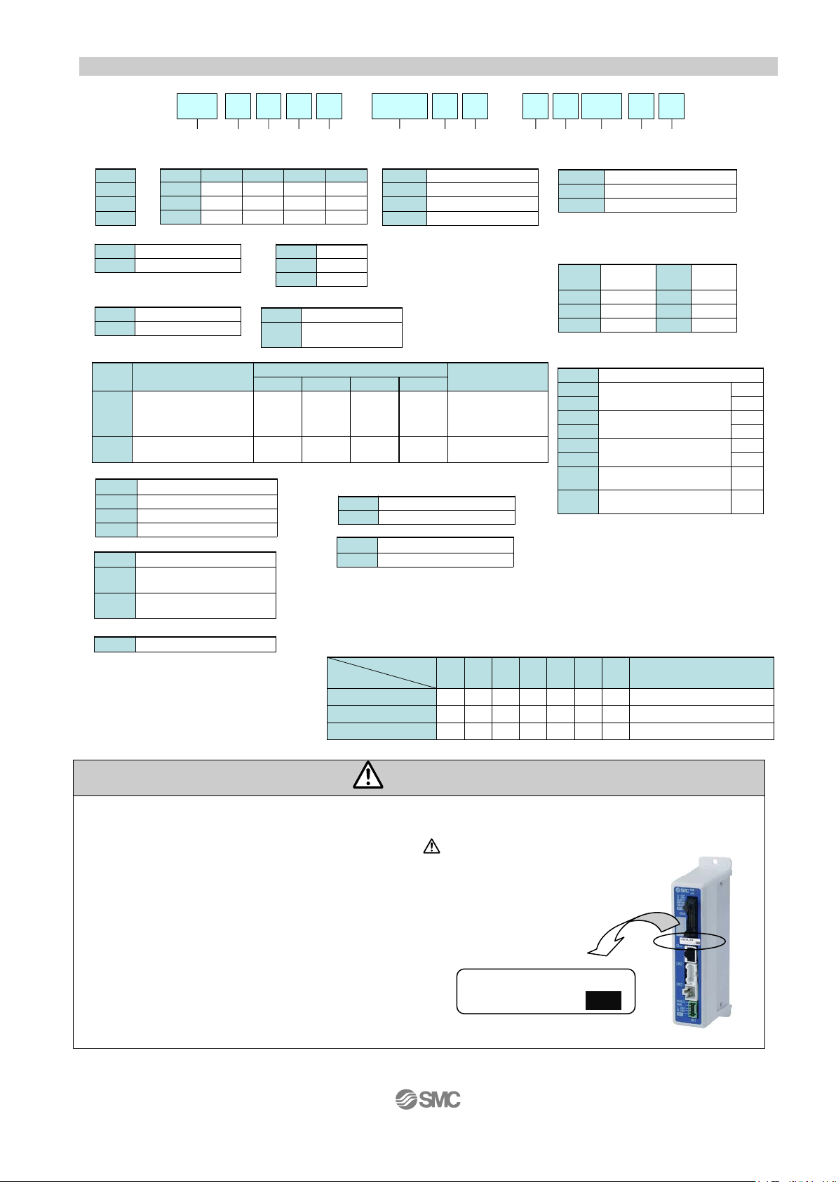
Caution
If when only the actuator is purchased separately, confir m that t he combinat io n of the controll er, which
(1)
(2)
LEY16B-100
NPN
*Applicable stroke table
●
-
-
500
15 to 400-
●●●●
●
●●●●
LEY25
●
-
450
●
-
350
●
●
250
●
●
150
●
●
30
●
●
50
●
●
200
●
-
400
●
●
300
●
●
100
20 to 500
10 to 300
Manufacturable
stroke range[mm]
LEY32 / LEY40
LEY16
●
-
-
500
15 to 400-
●●●
●●●●●●
LEY25
●
-
450
●
-
350
●
●
250
●
●
150
●
●
30
●
●
50
●
●
200
●
-
400
●
●
300
●
●
100
20 to 500
10 to 300
Manufacturable
stroke range[mm]
LEY32 / LEY40
LEY16
Model
Storoke
[㎜]
Model
Storoke
[㎜]
*Consult with SMC for the manufacture of intermediate strokes.
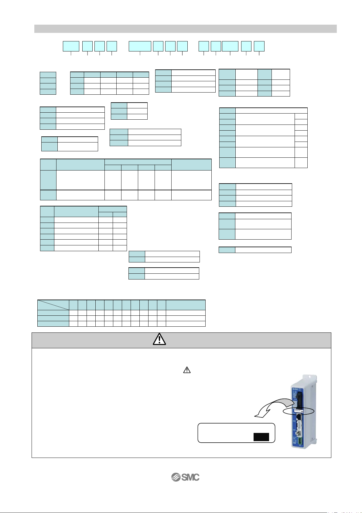
① Size
② Motor mounting position
Nil Top mounting type
R Right side parallel type
L Left side parallel type
D In-line type
④ Lead[mm]
⑤ Stroke [mm]
30
30
to
to
500
500
⑥ Motor option
Nil Without option
C With motor cover
B With lock
W With lock/motor cover
⑦ Rod end thread
Nil
Rod end female thread
M
Rod end male thread
(1 rod end nut included)
⑧ Mounting
Symbol
Type
Motor mounting
Parallel In-line
Nil
Ends tapped (Standard)
● ●
U Body bottom tappe d
● ●
L Foot
●
-
F Rod flange
● ●
G Head flange
●
-
D Double clevi s
●
-
⑨ A ctuator cable type
Nil Without cable
B Standard cable
R
Robotic cable(Flexible cable)
* The standard cable should be used on fixed parts.
For using on moving parts, select the robotic cable.
* Only available for the motor type “Step motor”.
* Mounting bracket is shipped together, (but not assembled).
* When mounting styles are [Rod/Head flange] or
[Ends tapped] with horizontal cantilever, use it within the
Following stroke.
・LEY25:200 or less ・LEY32/40:100 or less
* In case of [Double clevis], use the actuator within the
following stroke limit.
・LEY16:100 or less・LEY25:200 or less ・LEY32:200 or less
* “G” Head flange is not available for LEY32
LEY B 6N100 1- 1
40
-
S
①
② ④ ⑥ ⑦ ⑧ ⑨ ⑩ ⑫⑪
⑤③
⑬
16
25
32
40
③ Motor type
Symbol
Type
Size
Compatible
Controller
LEY16 LEY25 LEY32 LEY40
Nill
Step motor
(Servo/24 VDC)
● ● ● ●
LECP6
LECP1
LECPA
LECPMJ
JXC9
A
Servo motor
( 24 VDC )
● ●
- - LECA6
symbol
LEY16 LEY25 LEY32 LEY40
A 10 12 16 16
B 5 6 8 8
C 2.5 3 4 4
* For 30 stroke or less of size 16 with
[Motor mounting position: “Top” and
“Parallel type], when [With lock] is
selected, the motor projects through
the end of the body.
Select after confirming interface with
such as work pieces.
⑩ A ctuator Cable length [m]
Nil
Without
cable
8 8
*
1 1.5 A 10
*
3 3 B 15
*
5 5 C 20*
* Produced upon receipt of order. (Robotic cable only)
⑪ Controller type
Nil Without controller
6N
LECP6/LECA6
(Step data input type)
NPN
6P PNP
1N
LECP1
*1
(Program-less type)
NPN
1P PNP
AN
LECPA
*1
(Pulse input type)
NPN
AP PNP
MJ
LECPMJ
*1, *2
(CC-Link direct input type)
-
C9
JXC9
*1,
(EtherNet/IP direct input type)
-
*1 Only available for the motor type “Step motor”.
*2 Not applicable to CE.
⑫ I/O Cable length [m] / 6* 1* A*
Nil Without cable
1
1.5
3
3
5
5
⑬ Controller / Driver option
Nil Screw mounting
D DIN rail mounting*
Nil Without cable
S
Straight type communication
plug connector
T
Straight type communication
plug connector
Communication plug connector / MJ*
1 1 axis, DC24V
Number of axis, and type of power supply / C9*
* When "Without controller/drivers" selected
for controller/driver type, I/O cable,
Communication plug connector,
Number of axis, and type of power
supply could not be selected.
7 Screw mounting
8 DIN rail mounting*
6* 1* A* MJ
C9
*DIN rail not included, Order it separately
2.2 How to Order
The actuator body and c ontr ol l er ar e sold as a package.
you have and the actuator is compatible. / See 6.3 Caution(1) on p.38
<Be sure to check the follow ing b ef or e use.>
(1) Check that actuator la bel for model number.
This matches the controll er.
(2) Check Parallel I /O conf igur ation matches (NPN or PNP).
- 11 -
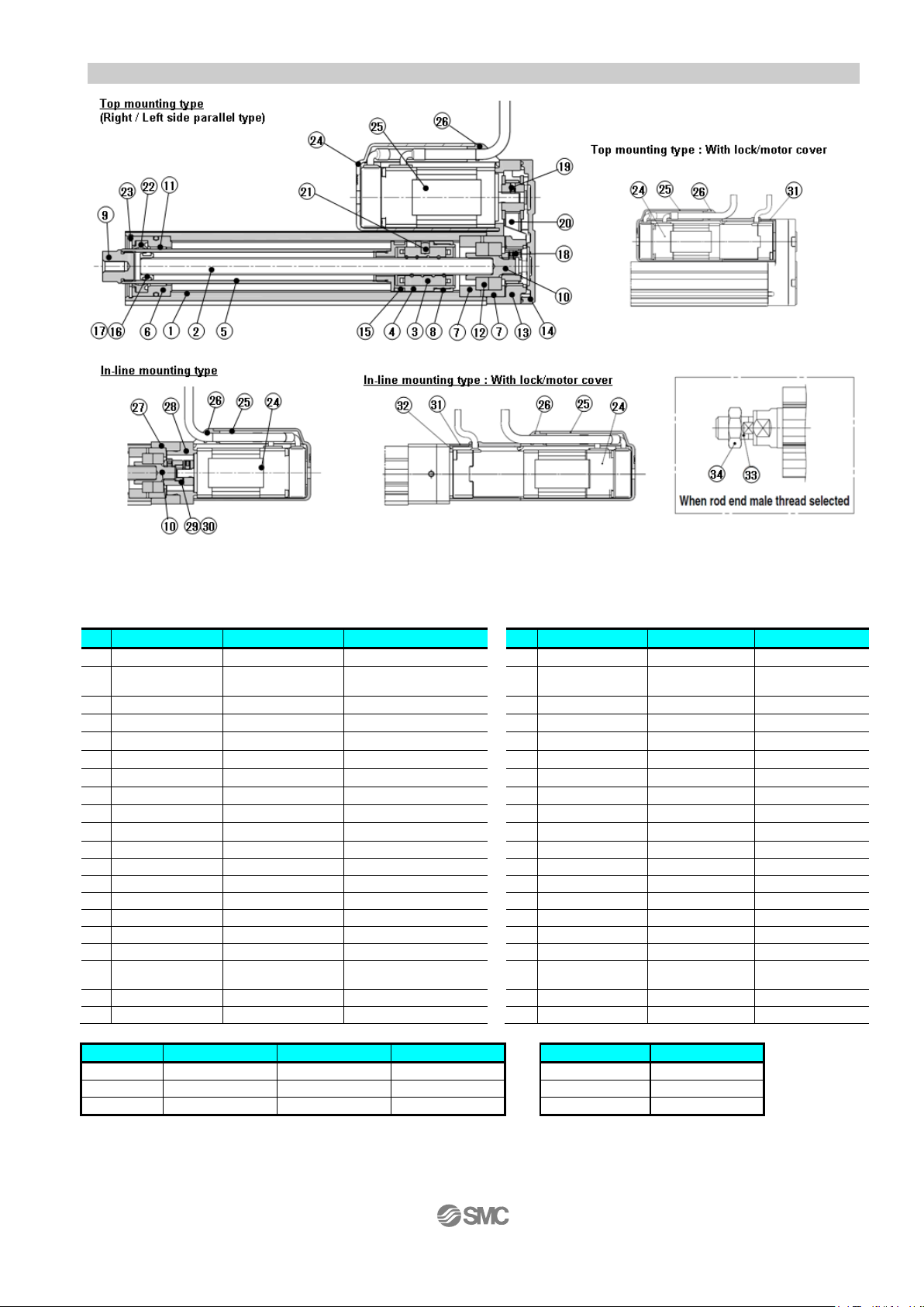
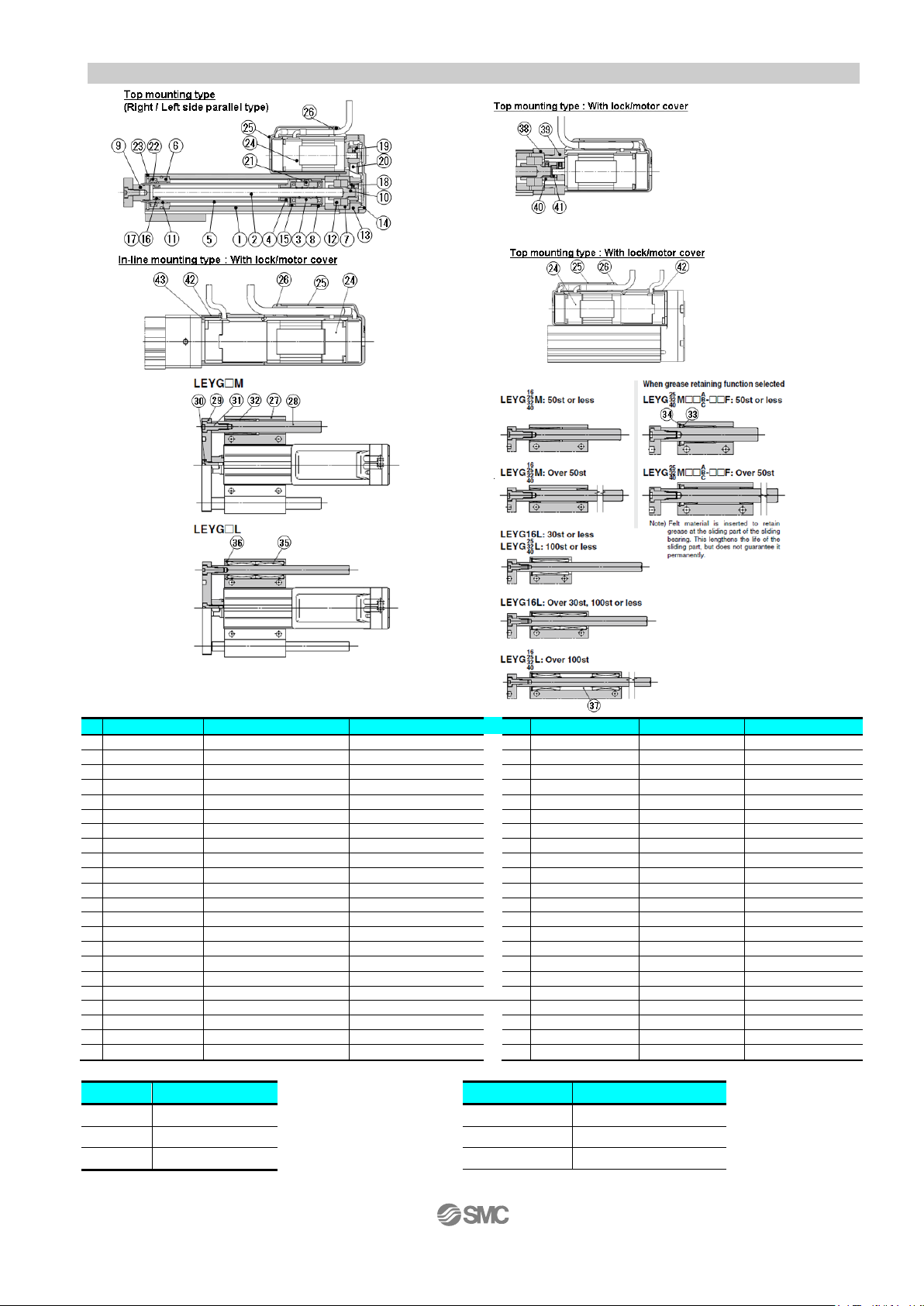
No.
Part
Material
Remarks
No.
Part
Material
Remarks
1
Body
Aluminum alloy
Anodized
21
Parallel pin
Stainless steel
High carbon chrome
bearing steel
3
Ball screw nut
Resin/Alloy steel
23
Retaining ring
Steel for spring
Phosphate coated
4
Piston
Aluminum alloy
24
Motor
-
5
Piston rod
Stainless steel
Hard chrome anodized
25
Motor cover
Plastic
Only “With motor cover”
6
Rod cover
Aluminum alloy
26
Grommet
Plastic
7
Bearing holder
Aluminum alloy
27
Motor block
Aluminum alloy
Anodized
8
Rotation stopper
Plastic
28
Motor adapter
Aluminum alloy
Anodized
9
Socket
Free cutting carbon steels
Nickel plated
29
Hub
Aluminum alloy
10
Free cutting carbon steels
Nickel plated
30
11
Bushing
Bearing alloy
31
Motor cover with lock
Aluminum alloy
Onl y “Wit h lock/motor cover”
12
Bearing
-
32
Cover support
Aluminum alloy
Onl y “Wit h lock/motor cover”
13
Return box
Aluminum die-cast
Coating
33
Socket(Male thread)
Free cutting carbon steels
Nickel plated
14
Return plate
Aluminum die-cast
Coating
34
Nut
Alloy steel
Zinc chromated
15
Magnet
-
16
Wear ring holder
Stainless steel
Only stroke 101mm or more
17
Wear ring
POM
Only stroke 101mm or more
Pulley
(For Screw shaft)
19
Pulley (For mo t or)
Aluminum alloy
20
Belt
-
Size
Foot
Flange
Double clevis
Size
Order no.
16
LEY-L016
LEY-F016
LEY-D016
16
LE-D-2-1
25
LEY-L025
LEY-F025
LEY-D025
25
LE-D-2-2
32
LEY-L032
LEY-F032
LEY-D032
32/40
LE-D-2-3
2.3 Construction
Parts list
Ball screw shaft
2
Connected shaft
18
Aluminum alloy
Rod seal
22
Sleeve NBR
NBR
Only “With motor cover”
Mounting bracket part number Replacement Parts(Top/Parallel only)/Belt
/ When ordering foot bracket, order 2 pieces per actuator.
/ Parts belonging to each bracket are as follows.
Foot, Flange: Body mounting bolt.
Double clevis: Clevis pin, Type C retaining ring for axis, Body mounting bolt.
- 12 -
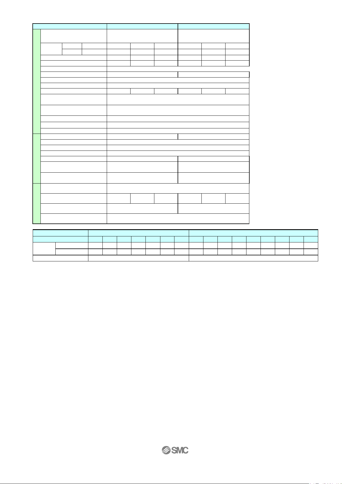
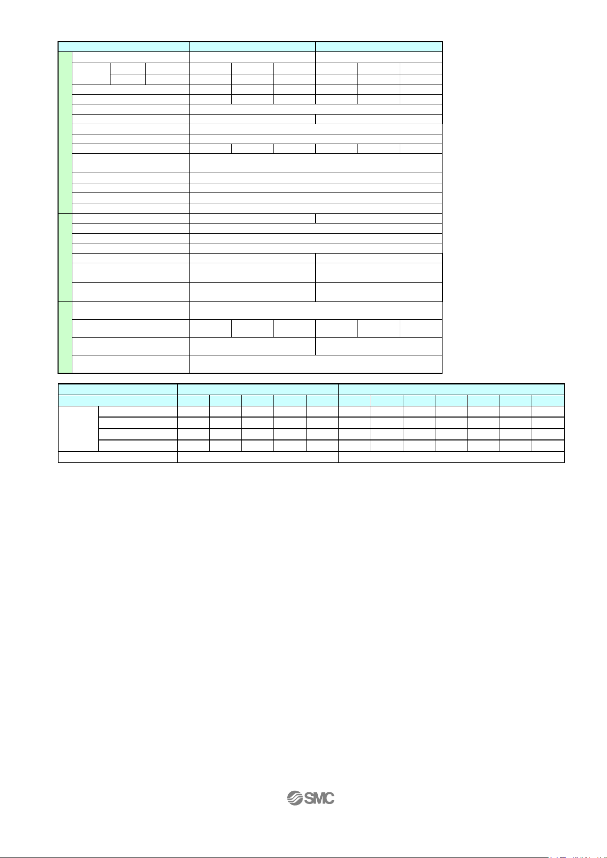
Model
LEYG 16
M
L
LEYG 25
M
L
LEYG 32
M
L
LEYG 40
M
L
Stroke [mm]
Note1)
Horizontal
LECP6,LECP1,LECPMJ)
(3000[mm2/s])
6
17
30
20
40
60
30
45
60
50
60
60
(2000[mm2/s])
10
23
35
30
55
70
40
60
80
60
70
90
(3000[mm2/s])
4
11
20
12
30
30
20
40
40
(2000[mm2/s])
6
17
30
18
50
50
30
60
60
Vertical
(3000[mm2/s])
1.5
3.5
7.5 7 15
29 9 20
41
11
25
51
Pushing force [N]
Note3)4) 5)
14 to 38
27 to 74
51 to 141
63 to 122
126 to 238
232 to 452
80 to 189
156 to 370
296 to 707
Speed [mm/s]
(Contoller type:
LECP6,LECP1,LECPMJ)
15 to 500
8 to 250
4 to 125
18 to 500
9 to 250
5 to 125
24 to 500
12 to 300
6 to 150
15 to 500
8 to 250
4 to 125
18 to 500
9 to 250
5 to 125
24 to 500
12 to 250
6 to 125
acceleration/deceleration
3,000 or less
Pushing speed [mm/s]
Note6)
50 or less
35 or less
30 or less
30 or less
Positioning repeatability [mm]
+/- 0.02
Lost motion [mm]
0.1 or less
Lead [mm]
10 5 2.5
12 6 3
16 8 4
16 8 4
Impact resistance/vibration
Resistance [m/s2]
Drive method
Ball screw and Belt (For “LEY*_ / R / L ”), Ball screw (For “LEY*D)
Guide type
Slide bearing (LEYG□M), Bal l bushing beari ng (LEY G□L)
Operating temperature range [℃]
5 to 40
Operating humidity range [%]
90 RH or less (No condensation)
Motor size
□28
□42
□56.4 (M)
□56.4 (L)
Type of Motor
Step motor (Servo 24VDC)
Encoder
Incremental A/B phase (800 pulse/rotation)
Rated voltage [VDC]
24 +/- 10%
Power consumption [W]
Note8)
23
40
50
50
Standby power consumption
when operating [W]
Moment max. power
Consumption [W]
Lock unit
s
Type
Note11)
No excitation operating type
Holding force [N]
20
39
78
78
157
294
108
216
421
127
264
519
Power consumption [W]
Note12)
3.6 5 5
5
Rated voltage [VDC]
24+/-10%
Model
LEYG 16 □
LEYG 25 □
Stroke [mm]
Note1)
30
50
100
150
200
30
50
100
150
200
250
300
LEYG□M [ _ /R/L]
0.83
0.97
1.20
1.49
1.66
1.67
1.86
2.18
2.60
2.94
3.28
3.54
LEYG□L [ _ /R/L]
0.84
0.97
1.14
1.43
1.58
1.68
1.89
2.13
2.56
2.82
3.14
3.38
LEYG□M D
0.84
0.97
1.20
1.49
1.66
1.66
1.85
2.17
2.59
2.93
3.27
3.53
LEYG□L D
0.84
0.97
1.14
1.43
1.58
1.67
1.88
2.12
2.55
2.81
3.13
3.37
Additional weight for lock [kg]
0.12
0.26
Model
LEYG 32 □
LEYG 40 □
Stroke [mm]
Note1)
30
50
100
150
200
250
250
30
50
100
150
200
250
300
LEYG□M [ _ /R/L]
2.91
3.17
3.72
4.28
4.95
5.44
5.88
3.21
3.47
4.02
4.58
5.25
5.74
6.18
LEYG□L [ _ /R/L]
2.91
3.18
3.57
4.12
4.46
5.17
5.56
3.21
3.48
3.87
4.42
4.96
5.47
5.86
LEYG□M D
2.90
3.16
3.71
4.27
4.94
5.43
5.87
3.20
3.46
4.01
4.57
5.24
5.73
6.17
LEYG□L D
2.90
3.17
3.56
4.11
4.65
5.16
5.55
3.20
3.47
3.86
4.41
4.95
5.46
5.85
Additional weight for lock [kg]
0.53
0.53
3. Guide rod type / LEYG Series
3.1 Specification (1) Step motor (servo 24VDC)
30, 50, 100, 150, 200 30, 50, 100, 150, 200, 250, 300 30, 50, 100, 150, 200, 250, 300 30, 50, 100, 150, 200, 250, 300
Actuator specification
Work
load
[kg]
note 2)
Note5)
(Contoller type:
Horizontal
(Contoller type:LECPA)
(Contoller type:LECPA)
Note7)
30 60 60
132 to 283 266 to 553 562 to 1058
24 to 500 12 to 350 6 to 175
24 to 300 12 to 150 6 to 75
50 / 20
Note9)
Electric specification
specification
Note10)
16 15 48 48
43 48 104 106
Weight
[kg]
Weight
[kg]
Note 1) The middle stroke other than the above are produced upon receipt of order.
Note 2) Horizontal: The maximum value of the work load for the positioni ng operation(External guide is necessary [Coefficient of friction:0.1
or less]. For the pushing operation the maximum workload is equal to the "Vertical workload"An external guide is
necessary to support the workload. The actual workload and transfer speed will depend on the type of external guide.
Vertical: The speed is dependent on the workload.Check the catalog data for the selected model.
Note 3) Pushing force accuracy is ±20% (F.S.).
Note 4)
The setting range for the "Pushin g f orce" is 35% to 85% (LEYG16), 35% to 65% (LEYG25), 35% to 85% (LEYG32), 3 5% to 65% (LEYG40).
For details of setting range and notes, refer 7.2 "INP output signal" p.41.
It is possible that the "Pushing force" and the "Duty ratio" will change dependent on the set value.
Note 5) The speed and force may change depending on the cable length, load and mounting conditions. Furthermore, if the cable
Note 6) "Pushing speed” is the allowable speed for the pushing operation.
length exceeds 5m then it will decrease by up to 10% for each 5m. (At 15m: Reduced by up to 20%)
Note 7) Impact resis tance:
No malfunction occurred when the actuator was tested with a drop tester in both an axial direction and perpendicular
direction to the lead screw. (The test was performed with the actuator in the initial state.)
Vibration resistance:
No malfunction occurred in a test ranging between 45 to 2000 Hz, when the actuator was tested in both an axial
direction and a perpendicular direction to the lead screw.
(The test was per formed with the actuator in the initial state.)
Note 8) The “Power consumption” (including the controll er) is for when the actuator is operating.
Note 9) The “Standby power consumption when operating” (including the c ontroller) is for when the actuator is stopped in the set
position during the operation, except during the pushing operation.
Note 10) The “Momentary max.power consumption” (including the controller) is for when the actuator is operating.
This value can be used for the selection of the power supply.
Note 11) With lock oniy.
Note 12) For an actuator with lock, add the power consumption for the lock.
- 13 -
(2) Servo motor (24VDC)
Model
LEYG 16
M
L
A
LEYG 25
M
L
A
Stroke [mm]
Note1)
30, 50, 100, 150, 200
30, 50, 100, 150, 200, 250, 300
Work load
[kg]
Horizontal
(3000[mm/s2])
3 6 12 7 15
30
Vertical
(3000[mm/s2])
1.5
3.5
7.5 2 5
11
Pushing force [N]
Note3)4)
16to30
30to58
57to111
18to35
37to72
66to130
Speed [mm/s]
2 to 500
1 to 250
1 to 125
2 to 500
1 to 250
1 to 125
acceleration/deceleration
3,000 or less
Pushing speed [mm/s]
Note5)
50 or less
50 or less
Positioning repeatability [mm]
+/- 0.02
Lost motion [mm]
0.1 or less
Lead [mm]
10 5 2.5
12 6 3
Impact resistance/vibration
Resistance [m/s2]
Drive method
Ball screw and Belt
Guide type
Slide bearing (LEYG□M), Bal l bushing beari ng (LEY G□L)
Operating temperature range [℃]
5 to 40
Operating humidity range [%]
90 RH or less (No condensation)
Motor size
□28
□42
Type of Motor
Servo motor (24VDC)
Encoder
Incremental A/B phase (800 pulse/rotation) /Z phase
Rated voltage [VDC]
24 +/- 10%
Power consumption [W]
Note7)
40
86
Standby power consumption
when operating [W]
Moment max. power
Consumption [W]
Model LEYG 16 □A
LEYG 25 □A
Stroke [mm]
Note1)
30
50
100
150
200
30
50
100
150
200
250
300
LEYG□M [ _ /R/L]
0.83
0.97
1.20
1.49
1.66
1.63
1.82
2.14
2.56
2.90
3.24
3.50
LEYG□L [ _ /R/L]
0.84
0.97
1.14
1.43
1.58
1.64
1.85
2.09
2.52
2.78
3.10
3.34
LEYG□M D
0.83
0.97
1.20
1.49
1.66
1.62
1.81
2.13
2.55
2.89
3.23
3.49
LEYG□L D
0.84
0.97
1.14
1.43
1.58
1.63
1.84
2.08
2.51
2.77
3.09
3.33
Additional weight for lock [kg]
0.12
0.26
note 2)
Actuator specification
Electric specification
Type
Note6)
Note8)
Note9)
Note10)
No excitation operating type
4 (Horizontal) / 6 (Vertical) 4 (Horizontal) / 12 (Vertical)
59 96
50 / 20
Holding force [N] 20 39 78 78 157 294
Power consumption [W]
Lock specification
Rated voltage [VDC] 24+/-10%
Note11)
3.6 5
Weight
[kg]
Note 1) The middle stroke other than the above are produced upon receipt of order.
Note 2) Horizontal: The maximum value of the work load for the positioning operat i on(External guide is necessary [Coefficient of friction:0.1
or less]. For the pushing operation the maximum workload is equal to the "Vertical workload"An external guide is
necessary to support the workload. The actual workload and transfer speed will depend on the type of external guide.
Vertical: Check the catalog data for the selected model.
The figures shown in ( ) are the maximum acceleration/deceleration values.Set these values to be 3000mm/s² or less.
Note 3) Pushing force accuracy is ±20% (F.S.).
Note 4) The setting range for the "Pushing force" is from 50% to 95%.
For details of setting range and notes, refer 7.2 "INP output signal" p.41.
It is possible that the "Pushing force" and the "Duty ratio" will change dependent on the set value.
Note 5) "Pushing speed” is the allowable speed for the pushing operation.
Note 6) Impact resistance:
No malfunction occurred when the actuator was tested with a drop tester in both an axial direction and perpendicular
direction to the lead screw.
(The test was performed with the actuator in the initial state.)
Vibration resistance:
No malfunction occurred in a test ranging between 45 to 2000 Hz, when the actuator was tested in both an axial
direction and a perpendicular direction to the lead screw.
(The test was performed with the actuator in the initial state.)
Note 7) The “Power consumption” (including the controller) is for when the actuator is operati ng.
Note 8) The “Standby power consumption when operating” (including the cont roller) is for when the actuator is stopped in the set
position during the operation with the maximum workload, except during the pushing operation.
Note 9) The “Momentary max.power consumption” (including the controller) is for when the actuator is operating.
This value can be used for the selection of the power supply.
Note 10) With lock oniy.
Note 11) For an actuator with lock, add the power consum ption for the lock.
- 14 -
Caution
If when only the actuator is purchased separately, confir m that t he combinat io n of the controll er, which
(1)
(2)
LEYG16MB-100
NPN
*Applicable stroke table
●
●
-
300
10 to 200
-
●●●●●
LEYG16
20 to 300
●●●●
●●
LEYG32/40
●
250
●
150
●30●
50
●
200
15 to 300
Manufacturable
stroke range[mm]
●
100
LEYG25
●
●
-
300
10 to 200
-
●●●●●
LEYG16
20 to 300
●●●●
●●
LEYG32/40
●
250
●
150
●30●
50
●
200
15 to 300
Manufacturable
stroke range[mm]
●
100
LEYG25
Model
Stroke
[㎜]
Model
Stroke
[㎜]
*Consult with SMC for the manufacture of intermediate strokes.
⑧ Guide option
Nil Without option
F
With grease
holding function
* Only available for slide bearings
② Bearing type
M Sliding bearing
L Ball bushing bearing
③ Motor mounting position
Nil T op mounting ty pe
D In-line type
⑥ Stroke [mm]
30
30
to
to
300
300
LEYG B A1
100
2-
16
-
S
①
③ ⑤ ⑦ ⑧ ⑨ ⑩ ⑫⑪
⑥
M
② ④ ⑬
① Size
16
25
32
40
⑤ Lead [mm]
symbol
LEYG16 LEYG25 LEYG32 LEYG40
A 10 12 16 16
B 5 6 8 8
C 2.5 3 4 4
⑦ Motor option
Nil Without option
C With motor cover
B With lock
W With lock/motor cover
* For 30 stroke or less of size 16 with
[Motor mounting position: “Top” and
“Parallel type], when [With lock] is
selected, the motor projects through
the end of the body.
Select after confirming interface with
such as work pieces.
④ Motor type
Symbol
Type
Size
Compatible
Controller
LEYG16 LEYG25 LEYG32 LEYG40
Nill
Step motor
(Servo/24 VDC)
● ● ● ●
LECP6
LECP1
LECPA
LECPMJ
JXC9
A
Servo motor
( 24 VDC )
● ●
- - LECA6
⑨ A ctuato r cable type
Nil Without cable
B Standard cable
R
Robotic cable(Flexible cable)
* The standard cable should be used on fixed parts.
For using on moving parts, select the robotic cable.
* Only available for the motor type “Step motor”.
⑩ Actuator Cable length [m]
Nil
Without
cable
8 8
*
1 1.5 A 10
*
3 3 B 15
*
5 5 C 20*
⑪ Controller type
Nil Without controller
6N
LECP6/LECA6
(Step data input type)
NPN
6P PNP
1N
LECP1
*1
(Program-less type)
NPN
1P PNP
AN
LECPA
*1
(Pulse input type)
NPN
AP PNP
MJ
LECPMJ
*1,*2
(CC-Link direct input type)
-
C9
JXC9
*1
(EtherNet/IP direct input type)
-
*1 Only available for the motor type “Step motor”.
*2 Not applicable to CE.
* Produced upon receipt of order. (Robotic cable only)
⑬ Controller / Driver optio n
Nil Screw mounting
D DIN rail mounting*
7 Screw mounting
8 DIN rail mounting*
6* 1* A* MJ
C9
*DIN rail not included, Order it separately
⑫ I/O Cable length [m] / 6* 1* A*
Nil Without cable
1
1.5
3
3
5
5
Nil Without cable
S
Straight type communication
plug connector
T
Straight type communication
plug connector
Communication plug connector / MJ*
1 1 axis, DC24V
Number of axis, and type of power supply / C9*
* When "Without controller/drivers" selected
for controller/driver type, I/O cable,
Communication plug connector,
Number of axis, and type of power
supply could not be selected.
3.2 How to Order
The actuator body and c ontr ol l er ar e sold as a package.
you have and the actuator is compatible. / See 6.3 Caution(1) on p.38
<Be sure to check the follow ing b ef or e use.>
(1) Check that actuator la bel for model number.
This matches the controll er.
(2) Check Parallel I /O conf igur ation matches (NPN or PNP).
- 15 -
No.
Part
Material
Remarks
No
Part
Material
Remarks
1
Body
Aluminum alloy
Anodized
23
Retaining ring
Carbon tool steel
Phosphate coated
2
Ball screw shaft
High carbon chrome bearing steel
24
Motor
- 3
Ball screw nut
Resin allo y st e el
25
Motor cover
Plastic
Only “With motor cover”
4
Piston
Aluminum alloy
26
Grommet
Plastic
Only “With motor cover”
5
Piston rod
Stainless steel
Hard chrome anodized
27
Guide attachment
Aluminium alloy
Anodized
6
Rod cover
Aluminum alloy
28
Guide rod
Carbon stee l
Hard chrom e pl ated
7
Bearing holde r
Aluminum alloy
29
Plate
Aluminium alloy
Anodized
8
Rotation stopper
Plastic
30
Plate mounting bolt
Carbon tool steel
Nickel plat e d
9
Socket
Free cutting carbon steels
Nickel plated
31
Guide bolt
Carbon tool steel
Nickel plat e d
10
Connected shaft
Free cutting carbon steels
Nickel plat e d
32
Slide Beari ng
Bearing alloy
11
Bushing
Bearing alloy
33
Felt
Felt 12
Bearing
-
34
Holder
Resin 13
Return box
Aluminum die-cast
Coating
35
Retaining ring
Carbon tool steel
Phosphate coated
14
Return plate
Aluminum die-cast
Coating
36
Ball bushing
- 15
Magnet
-
37
Spacer
Aluminium alloy
16
Wear ring holder
Stainless steel
Only stroke 101mm or more
38
Motor brock
Aluminium alloy
Anodized
17
Wear ring
POM
Only stroke 101mm or more
39
Motor adapter
Aluminium alloy
Anodized
18
Pulley (For Screw shaft)
Aluminum alloy
40
Hub
Aluminium alloy
19
Pulley (For motor)
Aluminum alloy
41
sleeve
NBR 20
Belt - 42
Motor cover with lock
Aluminium alloy
Only “With lock/motor cover”
21
Parallel pin
Stainless steel
43
Cover suppor t
Aluminium alloy
Only “With lock/motor cover”
22
Rod seal
NBR
Size
Part number
*Mounting bolt (2
Size
Order no.
16
LEYG-S016
16
LE-D-2-1
25
LEYG-S025
25
LE-D-2-2
32 / 40
LEYG-S032
32/40
LE-D-2-3
3.3 Construction
Support block Replacement Par ts(Top/Parallel only)/Belt
pieces) is included
in Support block.
- 16 -
 Loading...