

SMC Networks LESH16L, LESH16R, LESH25R, LESH8R, LESH25L Operation Manual
...
Doc. no. LES-OM00210
PRODUCT NAME
Electric Slide Table
MODEL / Series / Product Number
LES Series
Applicable models: LESH[]R, LESH[]L,LESH[]D
R T ype
●Standard
/LESH[]R Series
D T ype
●Standard
/LESH[]D Series
L Type
●Standard
/LESH[]L Series
<Controller>
LEC Series
This manual describes the actuators operation in combination with the LEC*6 series controllers.
Refer to the manual relevant to the controller being used for full operating instructions.

Contents
Safety Instructions............................................................................. 2
1. Procedure before operation/simple setting to use straight away4
1.1 Preparation................................................................................ 4
1.2 Controller setting software version......................................... 5
1.3 Teaching box ............................................................................. 7
2. Electric Slide table /LES Series..................................................... 9
2.1 Specification.............................................................................. 9
2. 2 How to Order .......................................................................... 13
2.3 Construction ........................................................................... 14
3. Product Outline ............................................................................ 16
3.1 System construction .............................................................. 16
3.2 Setting Function...................................................................... 17
3.3 Step data setting ..................................................................... 20
3.4 Parameter setting.................................................................... 31
4. Wiring of cables / Common precautions.................................... 35
5. Electric actuators / Common precautions ................................. 36
5.1 Design and selection .............................................................. 36
5.2 Mounting.................................................................................. 37
5.3 Handling .................................................................................. 37
5.4 Operating environment .......................................................... 39
5.5 Maintenance ............................................................................ 39
5.6 Precautions for actuator with lock ........................................ 40
6. Electric actuators / Common precautions ................................. 41
6.1 Design and selection .............................................................. 41
6.2 Handling .................................................................................. 41
6.3 Precaution on maintenance ................................................... 45
6.4 Replacement of belt ( LESH*R / LESH*L )............................. 46
6.5 How to spreading grease ....................................................... 48
7. Troubleshooting ........................................................................... 49
- 1 –
LES Series / Electric Slide table
Safety Instructions
These safety instructions are intended to prevent hazardous situations and /or equipment damage.
These instructions indicate the level of potential hazard with the labels of “Caution,” “Warning” or “Danger.”
They are all important notes for safety and must be followed in addition to International Standards (ISO
/IEC), Japan Industrial Standards (JIS)*1) and other safety regulations*2).
*1) ISO 4414: Pneumatic fluid power -- General rules relating to systems
ISO 4413: Hydraulic fluid power -- General rules relating to systems
IEC 60204-1: Safety of machinery -- Electrical equipment of machines (Part 1: General requirements)
ISO 10218-1992: Manipulating industrial robots -- Safety
JIS B 8370: General rules for pneumatic equipment.
JIS B 8361: General rules for hydraulic equipment.
JIS B 9960-1: Safety of machinery – Electrical equipment for machines. (Part 1: General requirements)
JIS B 8433-1993: Manipulating industrial robots - Safety. etc.
*2) Labor Safety and Sanitation Law, etc.
Caution
Warning
Danger
Caution indicates a hazard with a low level of risk which, if not avoided, could result in minor or
moderate injury.
Warning indicates a hazard with a medium level of risk which, if not avoided, could result in
death or serious injury.
Danger indicates a hazard with a high level of risk which, if not avoided, will result in death or
serious injury.
Warning
1. The compatibility of the product is the responsibility of the person who designs the equipment or
decides its specifications.
Since the product specified here is used under various operating conditions, its compatibility with specific
equipment must be decided by the person who designs the equipment or decides its specifications based on
necessary analysis and test results.
The expected performance and safety assurance of the equipment will be the responsibility of the person who
has determined its compatibility with the product.
This person should also continuously review all specifications of the product referring to its latest catalog
information, with a view to giving due consideration to any possibility of equipment failure when configuring the
equipment.
2. Only personnel with appropriate training should operate machinery and equipment.
The product specified here may become unsafe if handled incorrectly.
The assembly, operation and maintenance of machines or equipment including our products must be
performed by an operator who is appropriately trained and experienced.
3. Do not service or attempt to remove product and machinery /equipment until safety is confirmed.
The inspection and maintenance of machinery /equipment should only be performed after measures to
prevent falling or runaway of the driven objects have been confirmed.
When the product is to be removed, confirm that the safety measures as mentioned above are implemented
and the power from any appropriate source is cut, and read and understand the specific product precautions
of all relevant products carefully.
Before machinery /equipment is restarted, take measures to prevent unexpected operation and malfunction.
4. Contact SMC beforehand and take special consideration of safety measures if the product is to
be used in any of the following conditions.
1) Conditions and environments outside of the given specifications, or use outdoors or in a place exposed to
direct sunlight.
2) Installation on equipment in conjunction with atomic energy, railways, air navigation, space, shipping,
vehicles, military, medical treatment, combustion and recreation, or equipment in contact with food and
beverages, emergency stop circuits, clutch and brake circuits in press applications, safety equipment or other
applications unsuitable for the standard specifications described in the product catalog.
3) An application which could have negative effects on people, property, or animals requiring special safety
analysis.
4) Use in an interlock circuit, which requires the provision of double interlock for possible failure by using a
mechanical protective function, and periodical checks to confirm proper operation.
- 2 -

LES Series / Electric Slide table
Safety Instructions
Caution
The product is provided for use in manufacturing industries.
The product herein described is basically provided for peaceful use in manufacturing industries.
If considering using the product in other industries, consult SMC beforehand and exchange specifications
or a contract if necessary.
If anything is unclear, contact your nearest sales branch.
Limited warranty and Disclaimer /Compliance Requirements
The product used is subject to the following “Limited warranty and Disclaimer” and “Compliance
Requirements”.
Read and accept them before using the product.
Limited warranty and Disclaimer
The warranty period of the product is 1 year in service or 1.5 years after the product is delivered.*3)
Also, the product may have specified durability, running distance or replacement parts. Please
consult your nearest sales branch.
For any failure or damage reported within the warranty period which is clearly our responsibility, a
replacement product or necessary parts will be provided.
This limited warranty applies only to our product independently, and not to any other damage
incurred due to the failure of the product.
Prior to using SMC products, please read and understand the warranty terms and disclaimers noted
in the specified catalog for the particular products.
*3)
Vacuum pads are excluded from this 1 year warranty.
A vacuum pad is a consumable part, so it is warranted for a year after it is delivered.
Also, even within the warranty period, the wear of a product due to the use of the vacuum pad or failure
due to the deterioration of rubber material are not covered by the limited warranty.
Compliance Requirements
When the product is exported, strictly follow the laws required by the Ministry of Economy, Trade and
Industry (Foreign Exchange and Foreign Trade Control Law).
- 3 -
1. Procedure before operation/simple setting to use straight away
The controller is already set with the data of the actuator.
With the simple setting “easy mode”, it can be operated and running parameters can be changed easily.
1.1 Preparation
(1) Items to be prepared
Please check the label, and the quantity of accessories, to confirm that it is the product that was ordered.
Table 1. Components
No. Part name Qty
(1)
(2)
(3)
(4)
(5)
(6)
(7)
[The controller setting software, The communication cable, USB cable and conversion unit are included.]
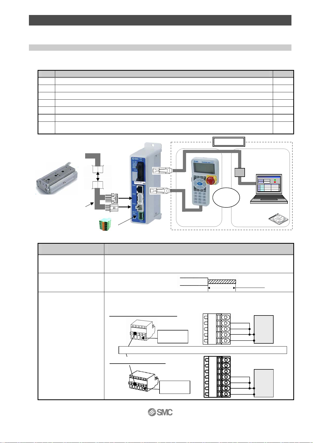
(1)Electric slide teble
(2) Controller
To CN3
(4)Actuator cable
(3)Power supply plug
To CN2
Table 2. Items to be prepared by the customer
I/O cable (Not use in this section)
To CN1
Electric slide teble
Controller
Power supply plug
Actuator cable
Teaching box
Controller setting kit
To CN4
(6)Teaching box
Option
or
(7)Controller
●Communication
cable
To USB port
モニタ
モニタ
現在位置
mm
現在位置
mm
120.3
120.3
現在速度
現在速度
mm/s
mm/s
200
200
設定
設定
位置 速度
位置 速度
100 500
1
テスト
100 500
1
テスト
2
テスト
2
テスト
200
200
3
テスト
3
テスト
50
50
PC
Setting kit
動作中
動作中
アラーム
アラーム
1000
1000
200
200
1
1
1
1
1
1
1
Part name Conditions
Power supply 24VDC
Do not use the power supply
with “Inruch-restraining type”
Wire AWG20 (0.5mm2)
Power supply plug
Wiring
Refer to power consumption of each actuator
/ See 2.1 Specification on p.9-12
(Prepare the power supply that has capacity of “Moment max.power consumption” or more.)
Stripped wire length
8mm
Connect the plus side of 24VDC to the C24V, M24V and EMG terminals of the power
supply plug, and the minus side to the 0V terminal.When conformity to UL is required,
the electric actuator and controller should be used with a UL1310 Class 2 power supply.
Step motor (servo 24VDC)
24VDC
power
suppiy
24V
0V
Electrical
wire entry
EMG
C24V
M24V
0V
Push the open/clese lever and insert the wire into the electrical wire entry
Servo motor (24VDC)
24VDC
power
suppiy
24V
0V
Electrical
wire entry
EMG
C24V
M24V
0V
- 4 -
1.2 Controller setting software version
1. Installation of software
With the controller setting software CD-ROM, install the communication unit software, following the
“Software Installation procedure” (PDF)
2. Startup of software
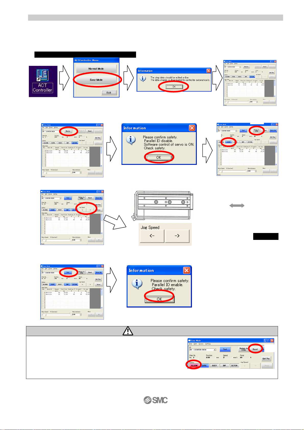
After turning on the controller power supply, start up the ACT Controller setting soft ware.
3. JOG Drive
a. Driving preparation: Servo On → Return to ORIG
Select “Monitor” Select “OK” (1)”SVRE” lighting is confirmed
b.JOG Drive (2) Select “Return to ORIG”
c. Driving stop: Servo Off
Select “Test” Select “OK”
Select “Easy Mode” Select “OK”
(2)
(1)
ExtendedRetracted
Cli
Clicking arrow button→Operation
Retracted
Extended
Caution
If an alarm is generated
(1) When ”ALARM” is generated, release it by selecting (2) Reset.
In the case of an alarm code that cannot be released with
“Reset”, turn the power supply OFF and ON again.
Note) For details of alarm codes, refer to the Controller Operation Manual.
- 5 -
(1)
(2)
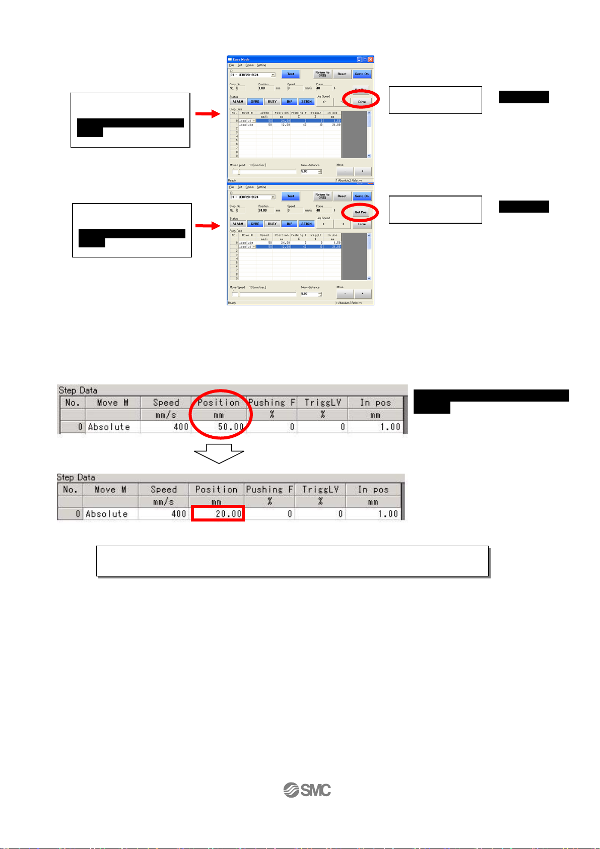
4. TEST Drive / Step No.0 → No.1 → No.0・・・
a. Driving preparation: Servo On → Return to ORIG / Refer to “3.JOG Drive”.
b.TEST Drive
“Step No.0” Operation
→ Operation
Procedure 1:
Select “Step No.0”
You can select anywhere in
the row
Procedure 2:
Select “Drive”
“Step No.1” Operation
→ Operation
Procedure 3:
Select “Step No.1”
You can select anywhere in
the row
Procedure 4:
Select “Drive”
c.Driving stop : Servo Off / Refer to “3.JOG Drive”.
5. Step data change
Ex) “Step No.0” / Positioning operation / At the time of shipment, Step No.0 is set to positioning operation
Change of positioning stop
position
Position: 50mm → 20mm
Input ”20”
For details of operation, and relationship between operation procedure and input/
output signals, refer to“3.3 Step Data” setting method p. 20 to 30.
6. Controller setting software screen explanation
Refer to the “Help / Easy mode” menu in the “ACT Controller” setting software.
- 6 -
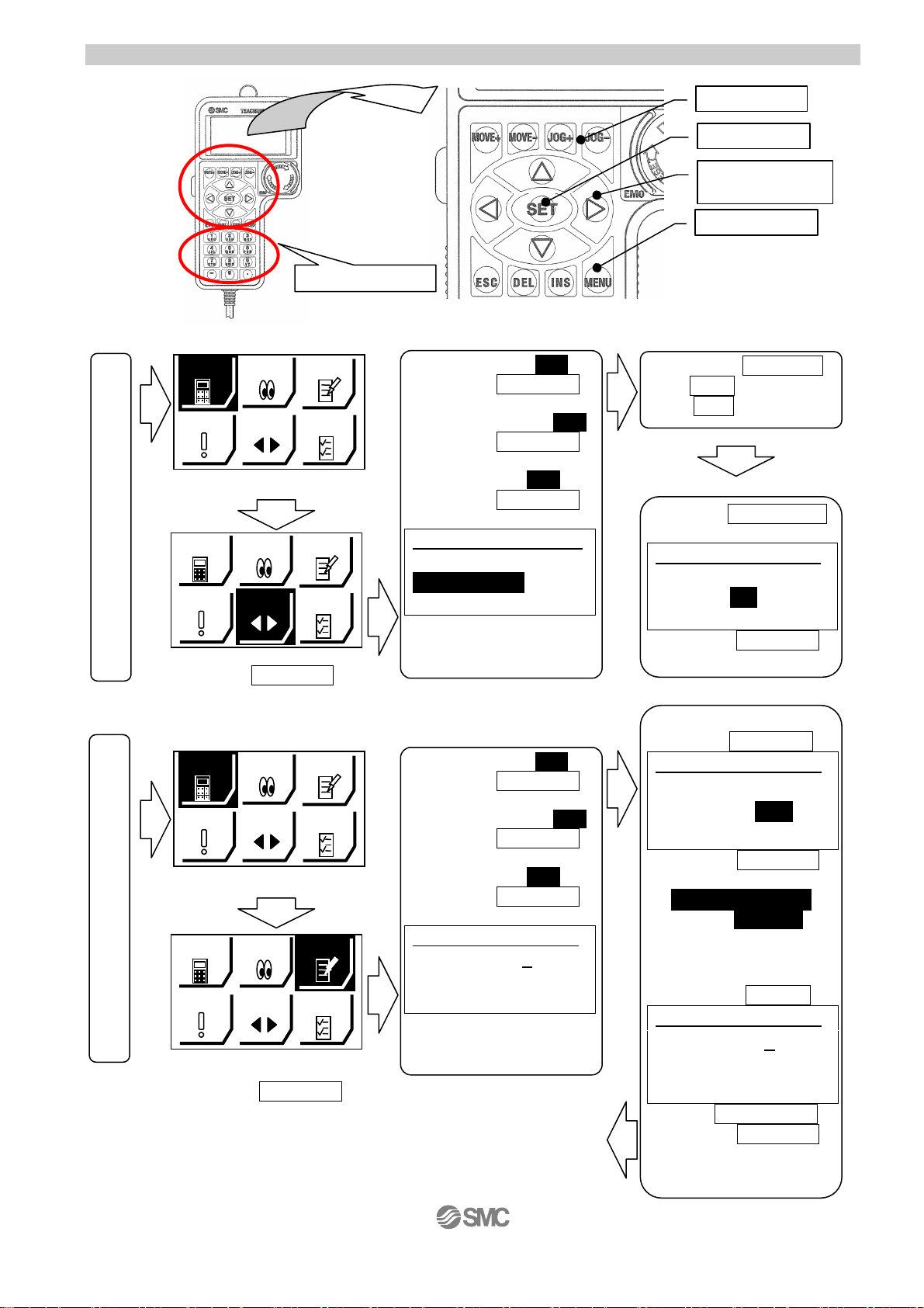
1.3 Teaching box
ジョグ
デ
ジョグ
デ
r
r
ジョグ
デ
ジョグ
デ
1. Name
(1) Number key
2. JOG Drive
ータ
DATA
モニタ
MONITOR
アラーム
ALARM
JOG
Select “JOG” Method of ending “JOG Drive”
supply is turned on.
ータ
DATA
モニタ
MONITOR
The powe
アラーム
ALARM
JOG
テスト
TEST
設定
SETTING
テスト
TEST
設定
SETTING
EXT Inp OFF:YES
Press the (3)SET key
↓
Servo ON,Ready?:YES
Press the (3)SET key
↓
RTN ORIG:Start
Press the (3)SET key
↓
AX
JOG 1
IS.
RTN ORIG Done
“JOG±”:Move
Posn 123.45mm
Operates by (2) JOG key
Press the (5)MENU key
Check 1
EXT Inp ON
Press the (3)SET key
3. TEST Drive / Step No.0 → No.1 → No.0・・・
ータ
DATA
モニタ
MONITOR
テスト
TEST
アラーム
ALARM
JOG
設定
SETTING
Servo ON,Ready?:YES
Select “TEST”
supply is turned on.
The powe
ータ
DATA
アラーム
ALARM
モニタ
MONITOR
JOG
テスト
TEST
設定
SETTING
Test 1
Step No. 0
Test Start
Posn 10.00mm
Press the (3)SET key
EXT Inp OFF:YES
Press the (3)SET key
↓
Press the (3)SET key
↓
RTN ORIG:Start
Press the (3)SET key
↓
<Work 1: Driving>
Press the
Test 1
Step No. 0
Test Start
Posn 10.00mm
<Work 2
Test 1
Step No. 1
Test Start
Posn 50.00mm
Press the (1)Number key”1”
Method of ending “TEST Drive”
It is the same as the Method
of ending “JOG Drive”
<Work 1: Driving>Repetition
- 7 -
(2) JOG key
(3)SET key
(4) Up and down,
right and left key
(5)MENU key
JOG+: extract
JOG-: retract
↓
AX
IS.
OK
Press the (3)SET key
(4)Down key
Press the (3)SET key
↓
Step No.0(Open)
Test Complete
↓
:Select Step No.>
Press the
(4)Up key
Press the (3)SET key
↓

4. Step data change
r
ジョグ
デ
“Step No.0” / Positioning operation
ータ
DATA
モニタ
MONITOR
テスト
TEST
アラーム
ALARM
JOG
SETTING
設定
supply is turned on.
Select “DATA”
Press the (3)SET key
The powe
Press the (5)MENU key
For details of operation, and relationship between operation procedure and input/
output signals, refer to“3.3 Step Data” setting method p. 20 to 30.
5. Teaching box detailed explanation
Please refer to the teaching box manual.
Screen to stop at
50mm position
Step 1
Step No. 0
Posn 50 .00mm
Force 0%
Press the (4)Down key
Select “Posn”
Method of ending “DATA”
Change of positioning
stop position
Posn 50 mm → 20mm
Step 1
Step No. 0
Posn 50 .00mm
Force 0%
Press the (1)Number key”20”
Press the (3)SET key
“Complete”
Step 1
Step No. 0
Posn 20 .00mm
Force 0%
- 8 -
2. Electric Slide table /LES Series
g
p
]
n
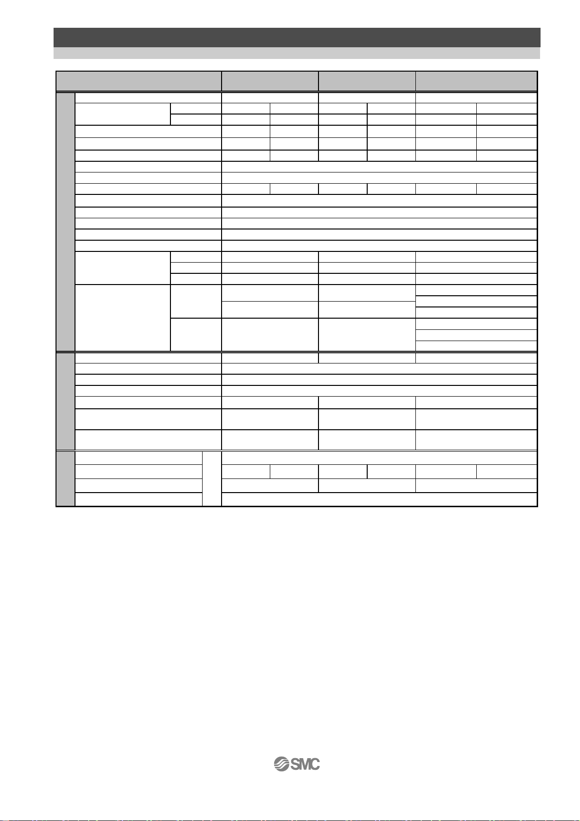
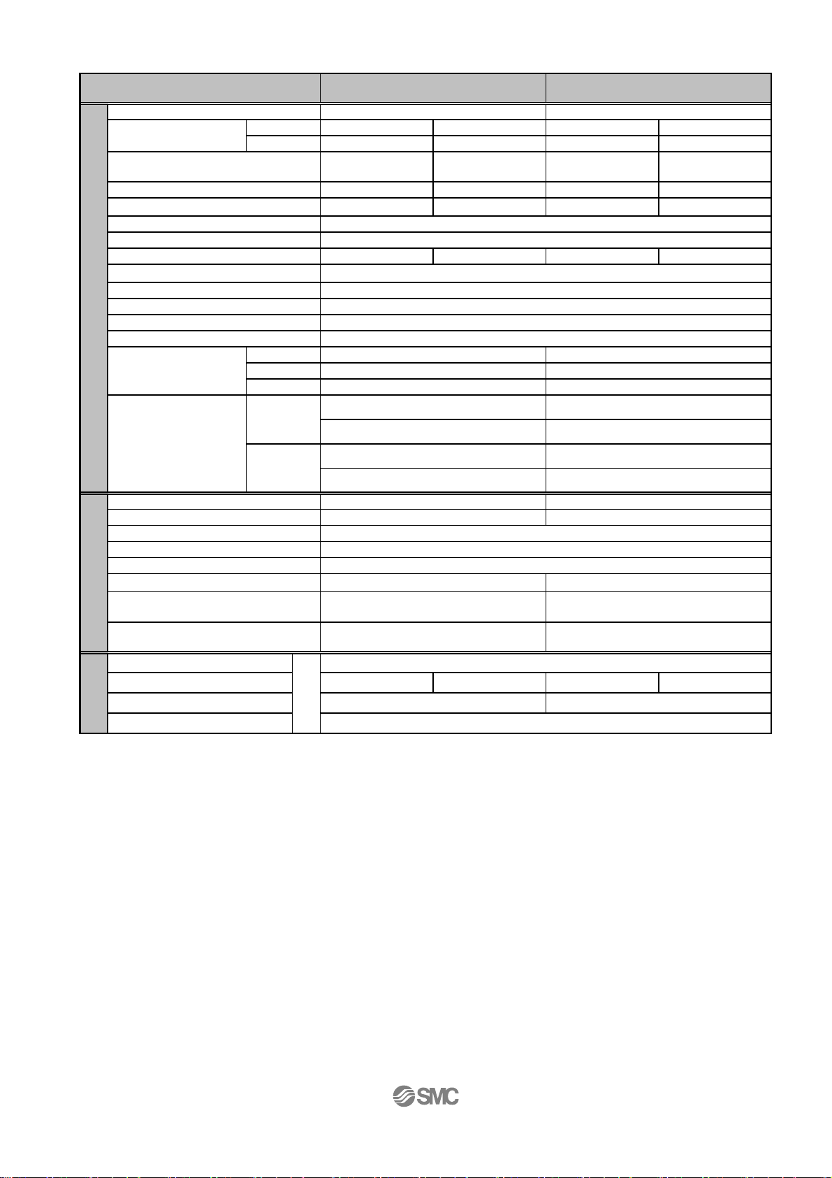
2.1 Specification
Step Motor (Servo 24VDC) / R,L Type
Size
Stroke [mm]
Work load
Note1)2)3)
[kg]
Pushing force [N] 30to70%
Speed [mm/s]
Pushing speed [mm/s]
Acceleration/Deceleration [mm/s
Positioning repeatability [mm] +/-0.05
Screw lead [mm]
Impact / vibration resistance [m/sec2]
Actuation type Slide screw + belt
Guide type Linear guide (circulating type)
Operating temp. range [℃] 5 to 40
Operating humidity range [%RH] 90 or less (No condensation)
Static Allowable
Actuator specification
Moment
[Nm]
Weight
[kg]
Motor size [mm] 20 28
Motor type HB type 2-phase step motor (Unipolar connection)
Encoder
Rated voltage [VDC] 24+/-10%
Power consumption [W]
Standby power consumption when
operatin
Moment max. power
Electric specification
consum
Type
Holding force [N] 24 2.5 300 48 500 77
Power consumption [W]
Rated voltage [VDC] 24+/-10%
Lock unit specificatio
[W]
tion[W
Note1)3)
Note6)
Note7)
Horizontal
Vertical
Note2)3)
2
]
Note4)
Pitching
Yawing
Rolling
Without lock
With lock 75st : 0.79 100st : 1.71
Note5)
Note9)
Note8)
50 , 75
2164 9 6
0.5 0.25 2 1 4 2
6 to 15 4 to 10 23.5 to 55 15 to 35 77 to 180 43 to 100
10 to 200 20 to 400 10 to 200 20 to 400 10 to 150 20 to 400
10 to 20 20 10 to 20 20 10 to 20 20
48510 8 16
50st : 0.55 50st : 1.15
75st : 0.70 100st : 1.60
R
LESH8
L
11
11
12
Incremental A/B phase (800 pulse/rotation)
20 43
715 13
35 60
43.6 5
LESH16 LESH25
50 , 100
5,000 or less
50st:26 / 100st:43
50st:26 / 100st:43 50st: 77/100st:112/150st:154
No excitation operating type
R
L
50 , 100 , 150
50 / 20
50st: 77/100st:112/150st:154
49 50st:146/100st:177/150st:152
50st : 2.50
100st : 3.30
150st : 4.26
50st : 2.84
100st : 3.64
150st : 4.60
Note 1) The speed is dependent on the workload. Check the “Speed-workload graphs” for the selected model in the catalogue
or the operation manual.
Note 2) The accuracy of the pushing force is ±20% of the max. pushing force.
The max. setting for the pushing force is 70% of the max. pushing force.
Note 3) The speed and force may change depending on the cable length, load and mounting conditions.
Furthemore, if the cable length exceeds 5m then it will decrease by up to 10% for each 5m.(At 15m : Reduced by up
to 20%)
Note 4) Impact resistance:
No malfunction occurred when the actuator was tested with a drop tester in both an axial direction and a perpendicular
direction to the lead screw. (The test was performed with the actuator in the initial state)
Vibration resistance:
No malfunction occurred in a test ranging between 45 to 2000 Hz when the actuator was tested in both an axial
direction and a perpendicular direction to the lead screw. (The test was performed with the actuator in the initial state)
Note 5) The "Power consumption" (including the controller) is for when the actuator is operating.
Note 6) The "Standby power consumption when operating" (including the controller) is for when the actuator is stopped in the
set position with no applied force in the direction of the actuator movement.
Note 7) The "Momentary max. power consumption" (including the controller) is for when the actuator is operating.
This value can be used for the selection of the power supply.
Note 8) Only applies to actuators supplied with a lock.
Note 9) For the actuator with lock, please add the power consumption for the lock.
R
L
42
67
74
- 9 -
g
n
p
(
)
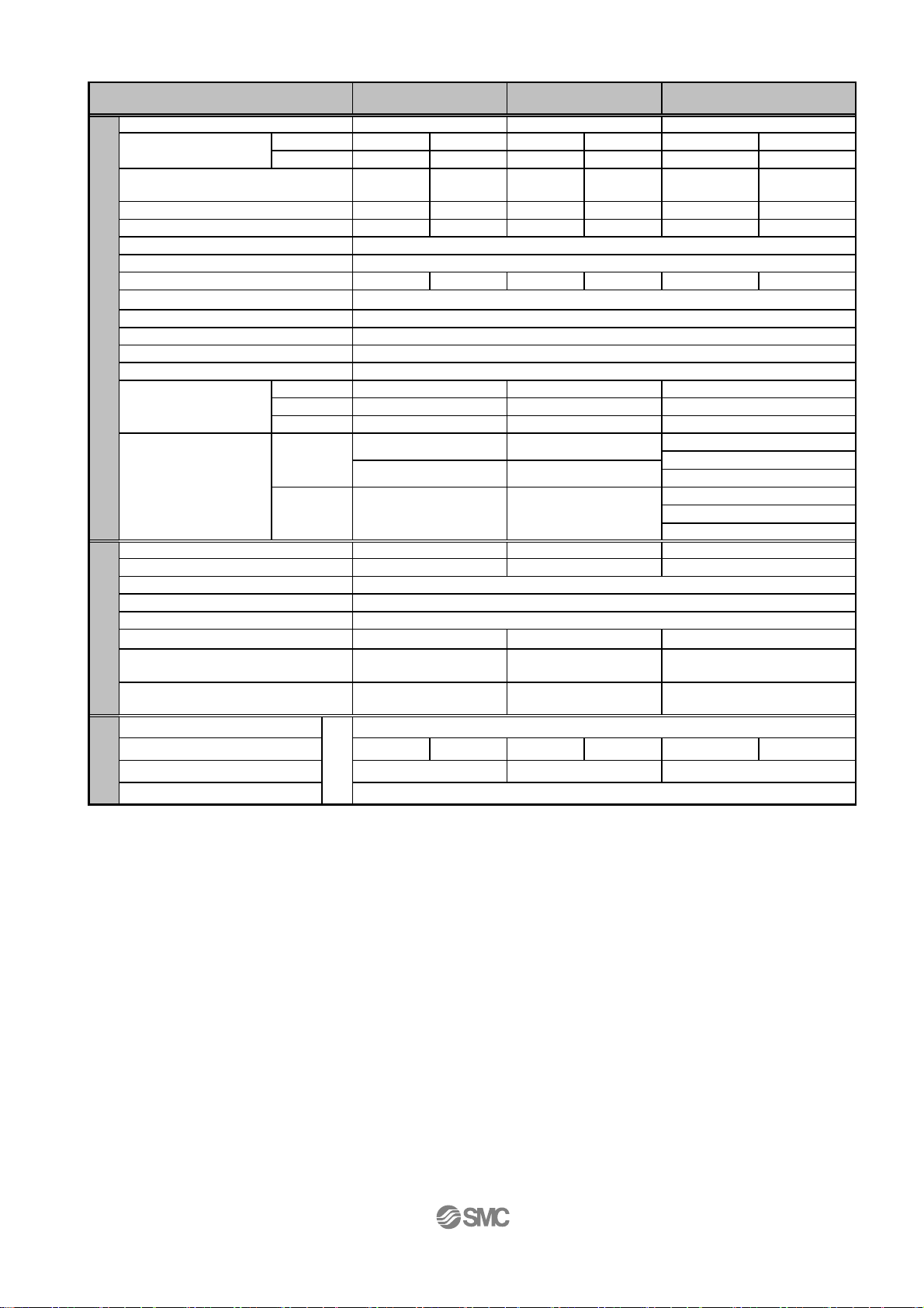
Servo Motor(24VDC) / R,L Type
Size LESH8 A
Work load
[kg]
Pushing force [N] 50to100%
LESH8[ ]A:50 to 75%
Speed [mm/s]
Pushing speed [mm/s]
Acceleration/Deceleration [mm/s2]
Positioning repeatability [mm] +/-0.05
Screw lead [mm]
Impact / vibration resistance [m/sec2]
Actuation type Slide screw + belt
Guide type Linear guide (circulating type)
Operating temp. range [℃] 5 to 40
Operating humidity range [%RH] 90 or less (No condensation)
Actuator specification
Static Allowable
Moment
[Nm]
Weight
[kg]
Motor size [mm]
Motor output [W] 10 30 36
Motor type
Encoder
Rated voltage [VDC]
Power consumption [W]
Standby power consumption
tion [W]
[W]
Note5)
when operatin
Electric specification
Moment max. power
consum
Type
Holding force [N]
Power consumption [W]
Rated voltage [VDC]
Lock unit specificatio
Horizontal
Vertical
Note1)
Note1)
Note2)
Pitching
Yawing
Rolling
Without lock
With lock
Note3)
Note4)
Note7)
2152.5 6 4
0.5 0.25 2 1 4 1.5
7.5 to 11 5 to 7.5 17.5 to 35 10 to 20 18 to 36 12 to 24
10 to 200 20 to 400 10 to 200 20 to 400 10 to 150 20 to 400
10 to 20 20 10 to 20 20 10 to 20 20
48510 8 16
Horizontal : 4
Vertical : 7
24 2.5 300 48 500 77
Note6)
R
L
50 , 75
11
11
12
50st : 0.55
75st : 0.70 100st : 1.60
75st : 0.79 100st : 1.71
20 28
Incremental A/B phase (800 pulse/rotation) / Z phase
58 84
84 124
4
LESH16 A LESH25 A
50st:26 / 100st:43
50st:26 / 100st:43 50st: 77/100st:112/150st:154
50st : 1.15
Servo motor (Servo 24VDC)
Horizontal : 2
Vertical : 15
No excitation operating type
R
L
50 , 100Stroke [mm]
5,000 or less
50 / 20
49 50st:146/100st:177/150st:152
24+/-10%
3.6 5
24+/-10%
50 , 100 , 150
50st: 77/100st:112/150st:154
100st : 3.30
150st : 4.26
100st : 3.64
150st : 4.60
Horizontal : 4
Vertical : 43
R
L
50st : 2.50
50st : 2.84
42
144
158
Note 1) The accuracy of the pushing force is ±20% of the max. pushing force.
The setting for the pushing force is 50-75% of LESH8[]A pushing force.
Note 2) Impact resistance: No malfunction occurred when the actuator was tested with a drop tester in both an
axial direction and a perpendicular direction to the lead screw.
(The test was performed with the actuator in the initial state)
Vibration resistance: No malfunction occurred in a test ranging between 45 to 2000 Hz. Test was
performed in both an axial direction and a perpendicular direction to the lead screw.
(The test was performed with the slide table in the initial state.)
Note 3) The "Power consumption" (including the controller) is for when the actuator is operating.
Note 4) The "Standby power consumption when operating" (including the controller) is for when the actuator is
stopped in the set position with no applied force in the direction of the actuator movement.
Note 5) The "Momentary max. power consumption" (including the controller) is for when the actuator is operating.
This value can be used for the selection of the power supply.
Note 6) Only applies to actuators supplied with a lock.
Note 7) For the actuator with lock, please add the power consumption for the lock.
- 10 -
n
p
]
g
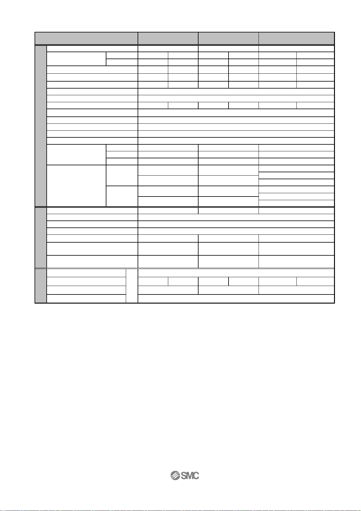
Step Motor (Servo 24VDC) / D Type
Size
Stroke [mm]
Work load
Note1)2)3)
[kg]
Pushing force [N] 30to70%
Speed [mm/s]
Pushing speed [mm/s]
Acceleration/Deceleration [mm/s
Positioning repeatability [mm] +/-0.05
Screw lead [mm]
Impact / vibration resistance [m/sec2]
Actuation type Slide screw
Guide type Linear guide (circulating type)
Operating temp. range [℃] 5 to 40
Operating humidity range [%RH] 90 or less (No condensation)
Static Allowable
Actuator specification
Moment
[Nm]
[kg]
Motor size [mm] 20 28
Motor type HB type 2-phase step motor (Unipolar connection)
Encoder
Rated voltage [VDC] 24+/-10%
Power consumption [W]
Standby power consumption when
operatin
Moment max. power
Electric specification
consum
Type
Holding force [N] 24 2.5 300 48 500 77
Power consumption [W]
Rated voltage [VDC] 24+/-10%
Lock unit specificatio
[W]
tion[W
Note1)3)
Note6)
Note7)
Horizontal
Vertical
Note2)3)
2
]
Note4)
Pitching
Yawing
Rolling
Without lock
With lock
Note5)
Note9)
Note8)
LESH8D LESH16D
50 , 75
2164 9 6
0.5 0.25 2 1 4 2
6 to 15 4 to 10 23.5 to 55 15 to 35 77 to 180 43 to 100
10 to 200 20 to 400 10 to 200 20 to 400 10 to 150 20 to 400
10 to 20 20 10 to 20 20 10 to 20 20
48510 8 16
11
11
12
50st : 0.57 50st : 1.25
75st : 0.70 100st : 1.70
50st : 0.66 50st : 1.36
75st : 0.79 100st : 1.81
Incremental A/B phase (800 pulse/rotation)
20 43 67
715 13
35 60 74
43.6 5
50 , 100
5,000 or less
50 / 20
50st:26 / 100st:43
50st:26 / 100st:43 50st: 77/100st:112/150st:154
49 50st:146/100st:177/150st:152
No excitation operating type
50st: 77/100st:112/150st:154
LESH25D
50 , 100 , 150
50st : 2.52
100st : 3.27
150st : 3.60Weight
50st : 2.86
100st : 3.61
150st : 3.94
42
Note 1) The speed is dependent on the workload. Check the “Speed-workload graphs” for the selected model in the catalogue
or the operation manual.
Note 2) The accuracy of the pushing force is ±20% of the max. pushing force.
The max. setting for the pushing force is 70% of the max. pushing force.
Note 3) The speed and force may change depending on the cable length, load and mounting conditions.
Furthemore, if the cable length exceeds 5m then it will decrease by up to 10% for each 5m.(At 15m : Reduced by up
to 20%)
Note 4) Impact resistance:
No malfunction occurred when the actuator was tested with a drop tester in both an axial direction and a perpendicular
direction to the lead screw. (The test was performed with the actuator in the initial state)
Vibration resistance:
No malfunction occurred in a test ranging between 45 to 2000 Hz when the actuator was tested in both an axial
direction and a perpendicular direction to the lead screw. (The test was performed with the actuator in the initial state)
Note 5) The "Power consumption" (including the controller) is for when the actuator is operating.
Note 6) The "Standby power consumption when operating" (including the controller) is for when the actuator is stopped in the
set position with no applied force in the direction of the actuator movement.
Note 7) The "Momentary max. power consumption" (including the controller) is for when the actuator is operating.
This value can be used for the selection of the power supply.
Note 8) Only applies to actuators supplied with a lock.
Note 9) For the actuator with lock, please add the power consumption for the lock.
- 11 -
r
g
(
)
Servo Motor(24VDC) /D Type
Size LESH8DA
LESH16DA
Stroke [mm]
Note1)
Note1)
Note4)
Horizontal
Vertical
2
]
Note2)
Pitching
Yawing
Rolling
Without lock
With lock
Note3)
Note7)
0.5 0.25 2 1
7.5 to 11 5 to 7.5 17.5 to 35 10 to 20
10 to 200 20 to 400 10 to 200 20 to 400
10 to 20 20 10 to 20 20
24 2.5 300 48
Note6)
Work load
[kg]
Pushing force [N] 50to100%
LESH8[ ]A:50 to 75%
Speed [mm/s]
Pushing speed [mm/s]
Acceleration/Deceleration [mm/s
Positioning repeatability [mm] +/-0.05
Screw lead [mm]
Impact / vibration resistance [m/sec2]
Actuation type Slide screw
Guide type
Operating temp. range [℃]5 to 40
Operating humidity range [%RH] 90 or less (No condensation)
Actuator specification
Static Allowable
Moment
[Nm]
Weight
[kg]
Motor size [mm]
Motor output [W]
Motor type
Encoder
Rated voltage [VDC]
Power consumption [W]
Standby power consumption
when operatin
Electric specification
Moment max. powe
consumption [W]
Type
Holding force [N]
Power consumption [W]
Rated voltage [VDC]
Lock unit specifica tion
[W]
Note5)
50 , 75
2152.5
5,000 or less
48510
50 / 20
Linear guide (circulating type)
11
11
12
50st : 0.57 50st : 1.25
75st : 0.70 100st : 1.70
50st : 0.66
75st : 0.79 100st : 1.81
20 28
10 30
Servo motor (Servo 24VDC)
Incremental A/B phase (800 pulse/rotation) / Z phase
24+/-10%
58 84
Horizontal : 4
Vertical : 7
84 124
No excitation operating type
4
24+/-10%
50 , 100
50st:26 / 100st:43
50st:26 / 100st:43
49
50st : 1.36
Horizontal : 2
Vertical : 15
3.6
Note 1) The accuracy of the pushing force is ±20% of the max. pushing force.
The setting for the pushing force is 50-75% of LESH8[]A pushing force.
Note 2) Impact resistance: No malfunction occurred when the actuator was tested with a drop tester in both an
axial direction and a perpendicular direction to the lead screw.
(The test was performed with the actuator in the initial state)
Vibration resistance: No malfunction occurred in a test ranging between 45 to 2000 Hz. Test was
performed in both an axial direction and a perpendicular direction to the lead screw.
(The test was performed with the slide table in the initial state.)
Note 3) The "Power consumption" (including the controller) is for when the actuator is operating.
Note 4) The "Standby power consumption when operating" (including the controller) is for when the actuator is
stopped in the set position with no applied force in the direction of the actuator movement.
Note 5) The "Momentary max. power consumption" (including the controller) is for when the actuator is operating.
This value can be used for the selection of the power supply.
Note 6) Only applies to actuators supplied with a lock.
Note 7) For the actuator with lock, please add the power consumption for the lock.
- 12 -
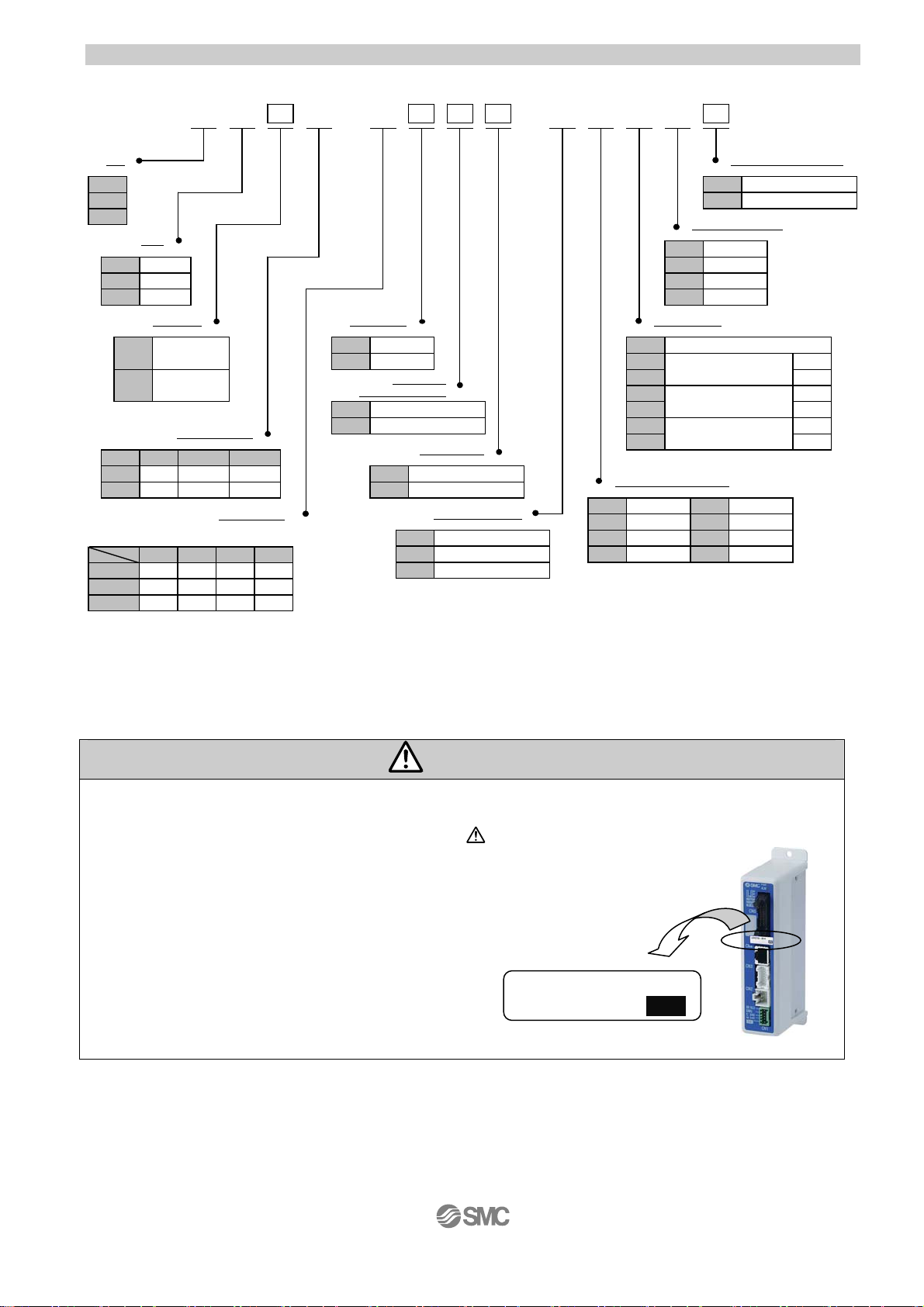
2. 2 How to Order
(1)
LE
-5016 R J
-R 1 6NSH 1
Size
8
16
25
Type
R
R type
L
L type
D
D type
Motor type
Step motor
Nill
(Servo DC24V)
Servo motor
*
A
(DC24V)
*LESH25DA cannot correspond.
Screw read (mm)
記号
LESH8
LESH16
J
8
10
K
4
5
Stroke (mm)
*Applicable types
75 100●150
50
LESH8
LESH16
LESH25
○
:
○
●
○
●
R/L type alone cannot correspond.
LESH25
●
●
Controller mounting style
Screw mounting style
Nill
DIN rail mounting style
D
I/O cable length (m)
Without cable
Nill
1
33
5
Motor option
Without lock
Nill
With lock
B
Body option
(Refer to left table)
Nill
S
16
8
*
Basic type
Dust proof specification
Mounting style
Without side holder
Nill
With side holder (4pcs)
H
Actuator cable type
Nill
R
S
*Only "Step motor" can be selected. (Only "Robotic type cable" can be selected.)
Without cable
With robotic type cabe
*
Standard cable
Nill 8
1
3
55
*Produced upon receipt of order.
Controller type
Nill
6N
(Step data input type)
6P
*
1N
*
1P
*
AN
*
AP
*Only "Step motor" can be selected.
Actuator cable length (m)
Without cable
1.5
3
1.5
5
Without controller
LECP6/LECA6
LECP1
(Programless type)
LECPA
(Pulse input type)
A
B
C
8
10
15
20
NPN
PNP
NPN
PNP
NPN
PNP
*
*
*
*
Caution
The actuator body and controller are sold as a package.
If when only the actuator is purchased separately, confirm that the combination of the controller, which
you have and the actuator is compatible. / See 5.3 Caution(1) on p.38
<Be sure to check the following before use.>
(1) Check that actuator label for model number.
This matches the controller.
(2) Check Parallel I /O configuration matches (NPN or PNP).
LESH8RJ-50
NPN
(2)
- 13 -
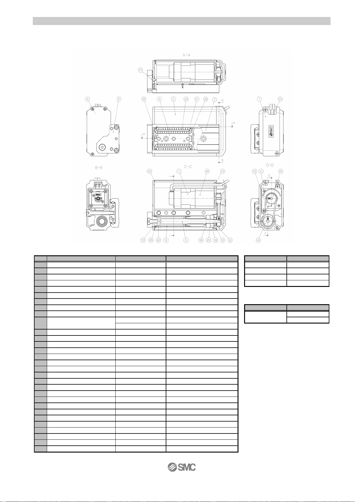
2.3 Construction
y
r
・LESH*R / LESH*L
Component parts
No. Description Material Remarks
1
Motor - - LESH8□ LE-D-1-1
Body Aluminum alloy Hard anodized LESH16
2
Teble Stainless steel Heat treated
3
4
Guide block Stainless steel Heat treated
Lead screw Stainless steel Special treatment
5
End plate Aluminum alloy Hard anodized
6
7
Pulle
8
9
10
11
12
13
14
15
16
17
18
19
20
21
22
23
24
25
26
27
28
29
30 Lock - -
cove
End cover Plastic - Parts Order number
Rod Stainless steel
Bearing holder
Motor plate Aluminum alloy -
Lock nut
Socket Carbon steel Electroless nickel plated
Lead screw pulley Aluminum alloy Motor pulley Aluminum alloy Spacer Stainless steel
Stopper Carbon steel Electroless nickel plated
Bearing
Belt - Grommet Plastic -
Simring Steel
Bushing - Dust proof only
Pulley gasket NBR Dust proof only
End gasket NBR Dust proof only
Scraper NBR Dust proof only
cover Plastic
Return guide Plastic
Scraper
Steel ball
Plastic -
Carbon steel Electroless nickel plated GR-S-020(20g)
Copper alloy
Special steel Chromate
--
Stainless steel and NBR
High carbon chrome bearing steel
B
B
- GR-S-010(10g)
Electrol ess nickel plated(LES H25R/L* only)
LESH25R/L* only
-
-
-
Linear guide
-
- 14 -
R type as shown
L type opposite as shown
Maintenance parts/belt
Size Part number
□
LESH25□ LE-D-1-3
LESH25□ALE-D-1-4
Maintenance parts/grease
Table
LE-D-1-2
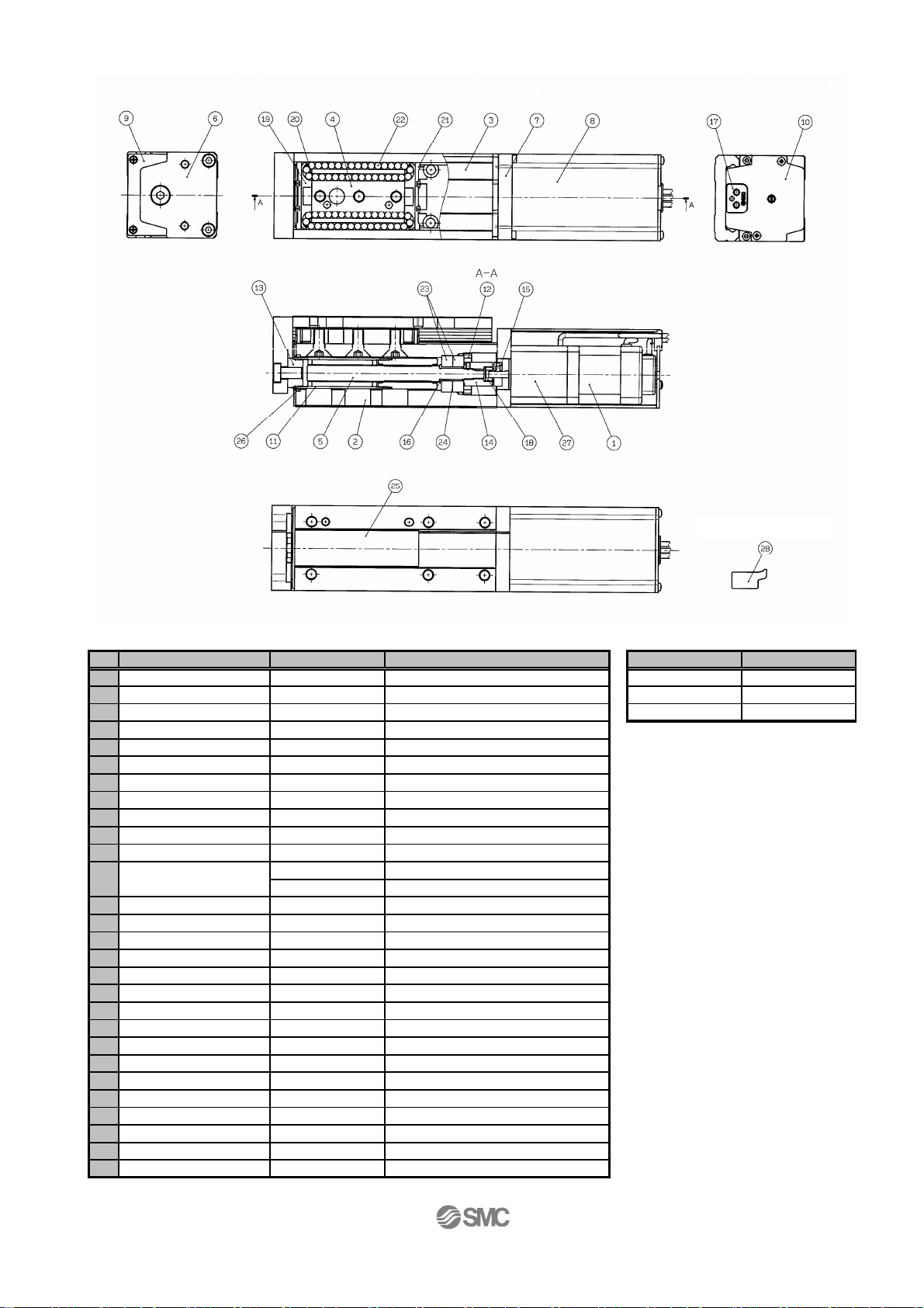
・LESH*D
Component parts
No. Description Material Remarks
1 Motor - 2 Body Aluminum alloy Hard anodized
3 Table Stainless steel Heat treatment + Electroless nickel
4 Guide block Stainless steel Heat treatment
5 Lead screw Stainless steel Heat treatment + Special plated
6 End plate Aluminum alloy Hard anodized
7 Motor flange Aluminum alloy Hard anodized
8 Motor cover Aluminum alloy Hard anodized
9 End cover Aluminum alloy Hard anodized
10 Motor end cover Aluminum alloy Hard anodized
11 Rod Stainless steel -
Bearing holder
12
13 Socket Carbon steel Electroless nickel plated
14 Hub(Screw side
15 Hub(Motor side
16 Spacer Stainless steel LESH25D* only
17 Grommet NBR 18 Spider NBR 19 Cover Plastic 20 Return guide Plastic 21 Scraper Stainless steel + Linear guide part
22 Steel ball Special steel 23 Bearing - 24 Shim ring Carbon steel 25 Masking tape - 26 Scraper NBR Dust proof only / rod part
27 Lock - 28 Side Holder Aluminum alloy Hard anodized
)
)
Carbon steel Electroless nickel plated
Copper alloy
Aluminum alloy Aluminum alloy -
Electroless nickel plated(LES H25R/ L* only)
- 15 -
Bundled shipment
Option parts/Side holder
Model Part number
LESH8D LE-D-3-1
LESH16D LE-D-3-2
LESH25D LE-D-3-3
3. Product Outline
)
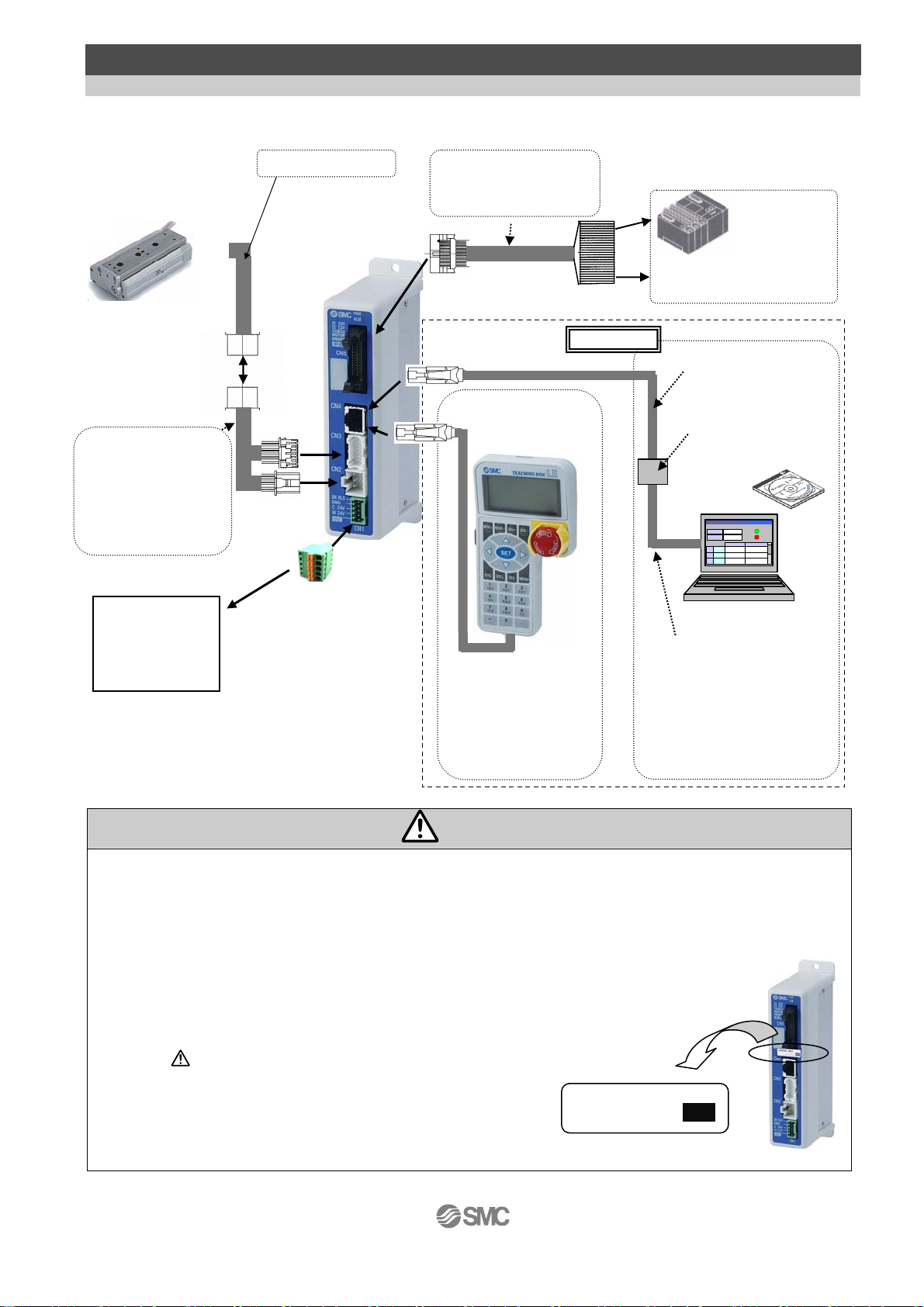
3.1 System construction
●Electric slide table
Note 1)
●Actuator cable
Part No:
-LE-C*-*-*
(Robotic type cable)
-LE-C*-*S-*
(Standard cable)
Note 2)
Controller
power supply
24VDC
●Power supply plug
<Applicable cable size>
Note 1): These items are included when it is selected
Note 2):
by ordering code.
When conformity to UL is required, the
electric actuator and controller should
be used with a UL1310 Class 2 power
supply.
Motor cable
Note 1)
●Controller
To CN3
To CN2
To CN1
AWG20 (0.5mm
Note 1
●I /O cable
Part No:LEC-CN5-
PLC
Note 2)
To CN5
Power supply
24VDC
Option
To CN4
●Communication
cable
●
Conversion
unit
or
モニタ
モニタ
現在位置
現在位置
現在速度
現在速度
設定
設定
1
1
2
2
3
3
動作中
動作中
mm
mm
120.3
120.3
アラーム
アラーム
mm/s
mm/s
200
200
位置 速度
位置 速度
100 500
テスト
100 500
テスト
1000
テスト
1000
テスト
200
200
200
テスト
200
テスト
50
50
PC
●USB cable
(A-miniB type)
2
)
●Teaching box
(with a cable of
3m long)
Part No:LEC-T1-3EG
●Controller setting kit
(
Controller setting software,
Communication cable,
Conversion unit and
USB cable are included.)
Part No:LEC-W2
Warning
Refer to the operation manual of the LEC (controller) for detailed wiring.
/ See “4 Wiring of cables” on p.35.
Communication cable is to be connected to PC by USB cable through conversion unit.
And do not connect teaching box to PC.
Do not connect the teaching box directly to the PC as there maybe
fire risk and damage to the PC or teaching box.
The actuator body and controller are sold as a package.
If when only the actuator is purchased separately, confirm that the combination
of the controller, which you have and the actuator is compatible.
/See 5.3 Caution(1) on p.38
<Be sure to check the following before use.>
(1) Check that actuator label for model number.
This matches the controller.
(2) Check Parallel I/O configuration matches (NPN or PNP).
- 16 -
(1)
LESH8RJ-50
NPN
(2)
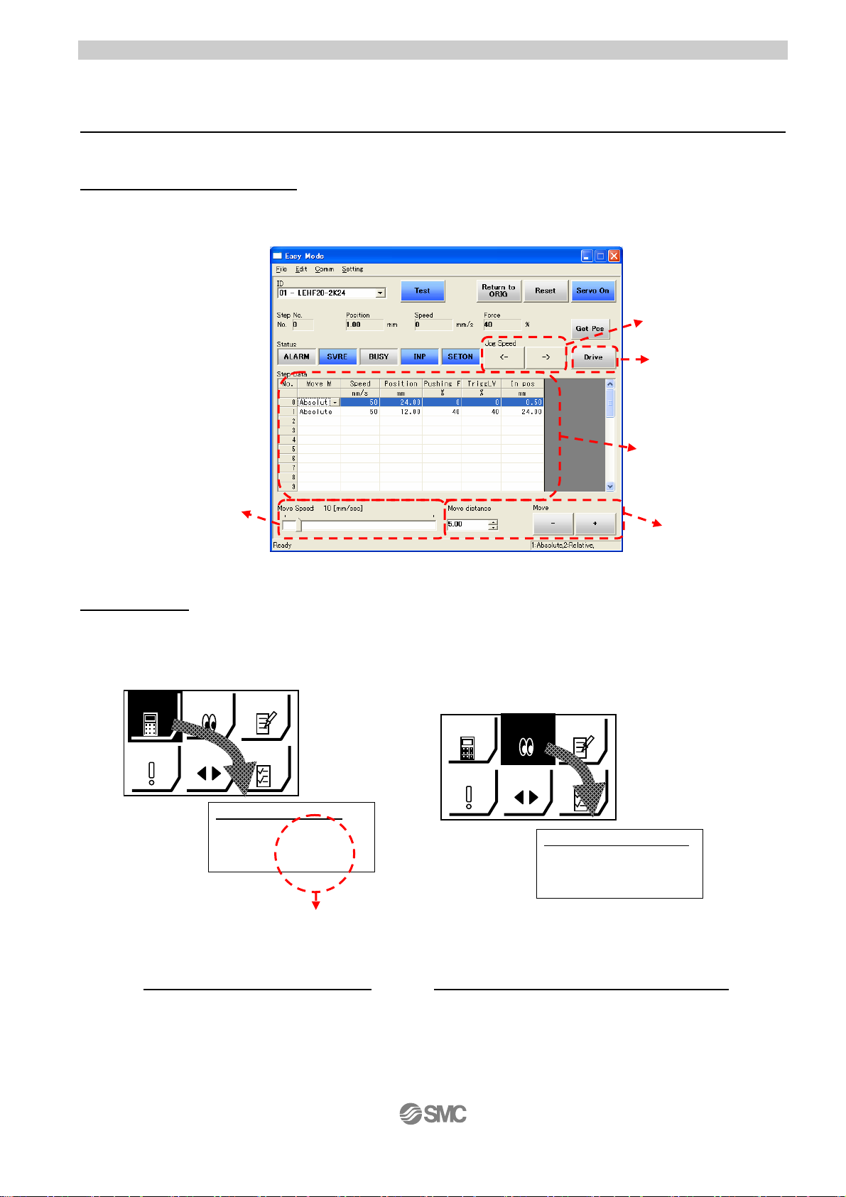
3.2 Setting Function
ジョグ
デ
ジョグ
デ
Refer to the operation manual of the controller (LEC series) for the detail of the setting function.
Easy Mode for simple setting
>Select “Easy mode” for instant operation
Controller setting software
Setting and operation, such as the step data setting, test drive and JOG / fixed-distance moving, can
be performed on the same page.
JOG moving
Start testing
Positioning
data setting
Speed setting of JOG /
fixed distance
Teaching box
Setting and operation by the simple screen without scrolling.
Select function by the iconized menu at the first page.
Step data setting and monitoring at the second page.
SETTING
テスト
TEST
設定
1st screen
2nd screen
Data Axis 1
Step No. 0
Posn 123.45mm
speed 400mm/s
It can be registered by “SET”
after entering the values.
ータ
DATA
アラーム
ALARM
ータ
DATA
アラーム
ALARM
モニタ
MONITOR
JOG
1st screen
モニタ
MONITOR
JOG
テスト
TEST
設定
SETTING
Monitor Axis 1
Step No. 1
Posn 12.34mm
speed 50mm/s
Operation status can be
checked
Fixed distance
moving
2nd screen
Example of setting the step data
Example of checking the operation status
- 17 -
 Loading...