

SMC Networks LER Series, LER*30K Series, LER*10J Series, LER*10K Series, LER*50J Series Operation Manual
...
PRODUCT NAME
Electric Rotary Table
MODEL / Series / Product Number
LER Series
This manual describes the actuators operation in combination with the LEC*6 series controllers.
Refer to the manual relevant to the controller being used for full operating instructions.
Doc. no. LER0-OM00303
<Controller>
LEC Series

- 1 –
Contents
Safety Instructions .................................................................................. 3
1. Procedure before operation/simple setting to use straight away ... 4
1.1 Preparation ................................................................................... 5
1.2 Controller setting software version ............................................ 6
1.3 Teaching box ................................................................................ 8
2. Electric Rotary Table /LER Series .................................................... 10
2.1 LER Series( Basic ・ External stopper ) ............................. 10
2.1.1 Specification ............................................................................................................................ 10
2.1.2 How to Order............................................................................................................................ 11
2.1.3 Construction ............................................................................................................................ 12
2.2 LER Series( Continuous rotation / 360° type ) ................... 14
2.2.1 Specification ............................................................................................................................ 14
2.2.2 How to Order............................................................................................................................ 15
2.2.3 Construction ............................................................................................................................ 16
3. Product Outline ................................................................................. 17
3.1 System construction ................................................................. 17
3.2 Setting Function ......................................................................... 18
3.3 Step data setting method .......................................................... 21
Positioning operation ...................................................................................................................... 21
Pushing operation ............................................................................................................................ 23
Operating procedure and input / output signals for each operation......................................... 29
Continuous rotation / 360° type setting ......................................................................................... 30
3.4 Parameter setting method ......................................................... 31
Initial setting for the basic parameters .......................................................................................... 31
Initial setting for the ORIG parameters .......................................................................................... 32
4. Wiring of cables / Common precautions ......................................... 33
5. Electric actuators / Common precautions ...................................... 34
5.1 Design and selection ................................................................. 34
5.2 Mounting ..................................................................................... 35
5.3 Handling ..................................................................................... 36
5.4 Operating environment ............................................................. 37
5.5 Maintenance ............................................................................... 38
5.6 Precautions for actuator with lock ........................................... 38
6. Electric Rotary Table /Specific Product Precautions ..................... 39
6.1 Design and selection ................................................................. 39
6.2 Mounting ..................................................................................... 39
6.3 Handling ..................................................................................... 40
6.4 Maintenance ............................................................................... 41

- 2 –
7. Troubleshooting ................................................................................ 42
- 3 -
LER Series/Electric Rotary Table
Safety Instructions
These safety instructions are intended to prevent hazardous situations and/or equipment damage.
These instructions indicate the level of potential hazard with the labels of “Caution,” “Warning” or “Danger.”
They are all important notes for safety and must be followed in addition to International Standards (ISO/IEC),
Japan Industrial Standards (JIS)*1) and other safety regulations*2).
*1) ISO 4414: Pneumatic fluid power -- General rules relating to systems
ISO 4413: Hydraulic fluid power -- General rules relating to systems
IEC 60204-1: Safety of machinery -- Electrical equipment of machines (Part 1: General requirements)
ISO 10218-1992: Manipulating industrial robots -- Safety
JIS B 8370: General rules for pneumatic equipment.
JIS B 8361: General rules for hydraulic equipment.
JIS B 9960-1: Safety of machinery – Electrical equipment for machines. (Part 1: General requirements)
JIS B 8433-1993: Manipulating industrial robots - Safety. etc.
*2) Labor Safety and Sanitation Law, etc.
Caution
Caution indicates a hazard with a low level of risk which, if not avoided, could result in minor or
moderate injury.
Warning
Warning indicates a hazard with a medium level of risk which, if not avoided, could result in
death or serious injury.
Danger
Danger indicates a hazard with a high level of risk which, if not avoided, will result in death or
serious injury.
Warning
1. The compatibility of the product is the responsibility of the person who designs the equipment or
decides its specifications.
Since the product specified here is used under various operating conditions, its compatibility with specific
equipment must be decided by the person who designs the equipment or decides its specifications based on
necessary analysis and test results.
The expected performance and safety assurance of the equipment will be the responsibility of the person who
has determined its compatibility with the product.
This person should also continuously review all specifications of the product referring to its latest catalog
information, with a view to giving due consideration to any possibility of equipment failure when configuring the
equipment.
2. Only personnel with appropriate training should operate machinery and equipment.
The product specified here may become unsafe if handled incorrectly.
The assembly, operation and maintenance of machines or equipment including our products must be
performed by an operator who is appropriately trained and experienced.
3. Do not service or attempt to remove product and machinery/equipment until safety is confirmed.
The inspection and maintenance of machinery/equipment should only be performed after measures to prevent
falling or runaway of the driven objects have been confirmed.
When the product is to be removed, confirm that the safety measures as mentioned above are implemented
and the power from any appropriate source is cut, and read and understand the specific product precautions
of all relevant products carefully.
Before machinery/equipment is restarted, take measures to prevent unexpected operation and malfunction.
4. Contact SMC beforehand and take special consideration of safety measures if the product is to
be used in any of the following conditions.
1) Conditions and environments outside of the given specifications, or use outdoors or in a place exposed to
direct sunlight.
2) Installation on equipment in conjunction with atomic energy, railways, air navigation, space, shipping,
vehicles, military, medical treatment, combustion and recreation, or equipment in contact with food and
beverages, emergency stop circuits, clutch and brake circuits in press applications, safety equipment or other
applications unsuitable for the standard specifications described in the product catalog.
3) An application which could have negative effects on people, property, or animals requiring special safety
analysis.
4) Use in an interlock circuit, which requires the provision of double interlock for possible failure by using a
mechanical protective function, and periodical checks to confirm proper operation.
- 4 -
LER Series/Electric Rotary Table
Safety Instructions
Caution
The product is provided for use in manufacturing industries.
The product herein described is basically provided for peaceful use in manufacturing industries.
If considering using the product in other industries, consult SMC beforehand and exchange specifications
or a contract if necessary.
If anything is unclear, contact your nearest sales branch.
Limited warranty and Disclaimer/Compliance Requirements
The product used is subject to the following “Limited warranty and Disclaimer” and “Compliance
Requirements”.
Read and accept them before using the product.
Limited warranty and Disclaimer
The warranty period of the product is 1 year in service or 1.5 years after the product is delivered.*3)
Also, the product may have specified durability, running distance or replacement parts. Please
consult your nearest sales branch.
For any failure or damage reported within the warranty period which is clearly our responsibility, a
replacement product or necessary parts will be provided.
This limited warranty applies only to our product independently, and not to any other damage
incurred due to the failure of the product.
Prior to using SMC products, please read and understand the warranty terms and disclaimers noted
in the specified catalog for the particular products.
*3) Vacuum pads are excluded from this 1 year warranty.
A vacuum pad is a consumable part, so it is warranted for a year after it is delivered.
Also, even within the warranty period, the wear of a product due to the use of the vacuum pad or failure due
to the deterioration of rubber material are not covered by the limited warranty.
Compliance Requirements
When the product is exported, strictly follow the laws required by the Ministry of Economy, Trade and
Industry (Foreign Exchange and Foreign Trade Control Law).
Caution
SMC products are not intended for use as instruments for legal metrology.
Measurement instruments that SMC manufactures or sells have not been qualified by type approval tests
relevant to the metrology (measurement) laws of each country.
Therefore, SMC products cannot be used for business or certification ordained by the metrology
(measurement) laws of each country.
- 5 -
8mm
(3) Power supply plug
Communication
cable
PC
(7) Controller
setting kit
位置 速度
100 500
200
1000
50
200
1
2
3
テスト
テスト
テスト
現在位置
120.3
現在速度
200
mm
mm/s
動作中
アラーム
モニタ
設定
位置 速度
100 500
200
1000
50
200
1
2
3
テスト
テスト
テスト
現在位置
120.3
現在速度
200
mm
mm/s
動作中
アラーム
モニタ
設定
1. Procedure before operation/simple setting to use straight away
The controller is already set with the data of the actuator.
With the simple setting “easy mode”, it can be operated and running parameters can be changed easily.
1.1 Preparation
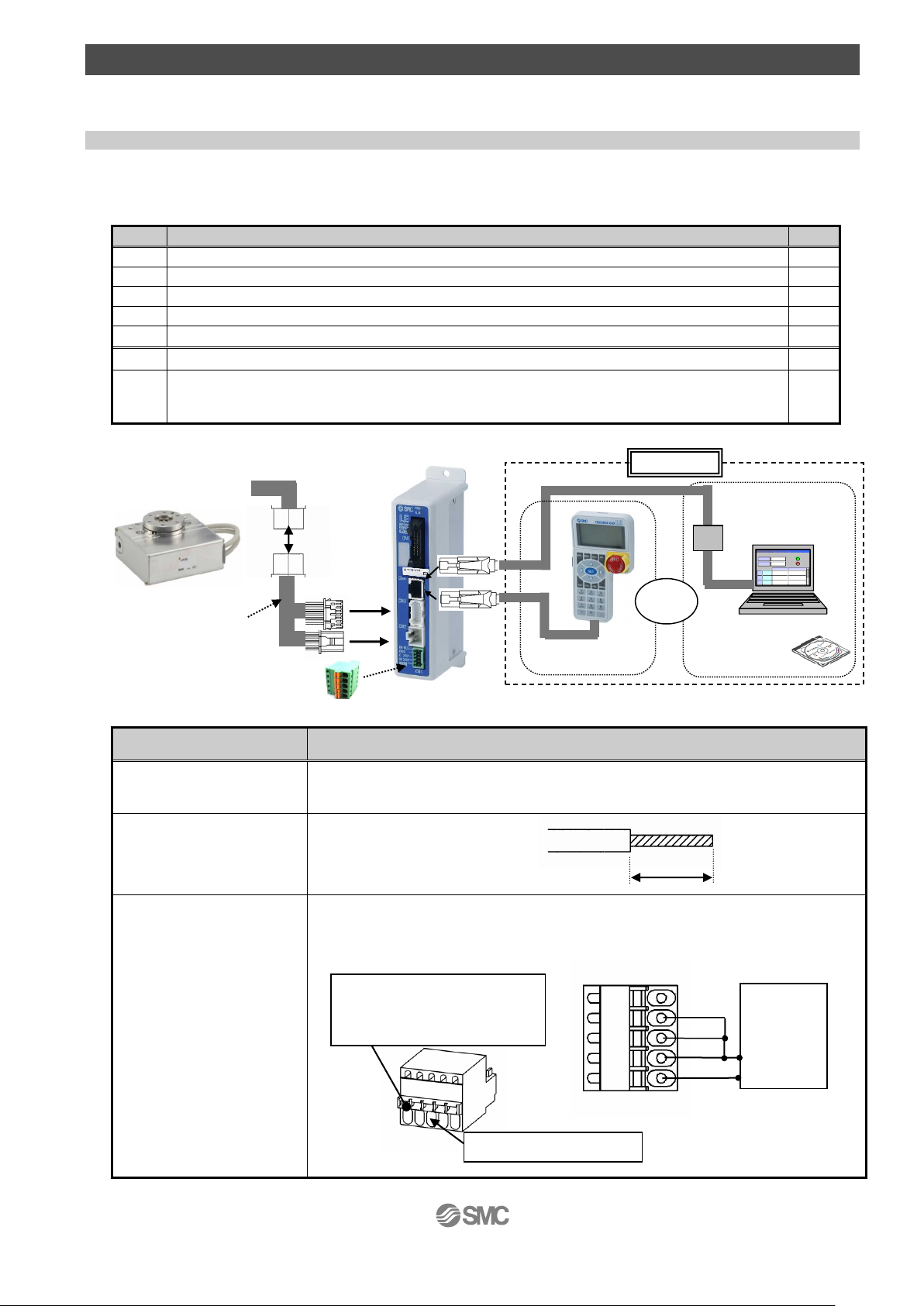
(1) Items to be prepared
Please check on the label, and the quantity of accessories, to confirm that it is the product that was
ordered.
Table 1. Componets
Table 2. Items to be prepared by the customer
No.
Part name
Qty
(1)
Electric Rotary Table
1
(2)
Controller
1
(3)
Power supply plug
1
(4)
Actuator cable
1
(5)
I/O cable (Not use in this section)
1
(6)
Teaching box
1
(7)
Controller setting kit
[The controller setting software, The communication cable, USB cable and conversion unit are included.]
Setting software / version 1.1or higher
1
Part name
Conditions
Power supply 24VDC
Except “inrush-current
restraining type”
Refer to power consumption of each actuator
Wire AWG20 (0.5mm2)
Power supply plug
Wiring
Connect the plus side of DC 24V to the C24V, M24V and EMG terminals of the power
supply plug, and the minus side to the 0V terminal. When conformity to UL is required,
the electric actuator and controller should be used with a UL1310 Class 2 power supply.
Stripped wire length
To CN3
(4) Actuator cable
(6) Teaching box
or
To USB port
Option
To CN2
To CN4
(1) Electric Rotary Table
To CN1
Electrical wire entry
Push the open/ close lever
and insert the wire into the
electrical wire entry.
0V
M24V
EMG
C24V
24V
0V
DC 24V
power
supply
- 6 -
1.2 Controller setting software version
(1) Installation of software
With the controller setting software CD-ROM, install the communication unit software, following the
“Software Installation procedure” (PDF)
※ When the controller setting software/version is below 1.1, the display unit is distance (mm), but the
product recognizes it as an angle(°). To upgrade the software, please go to the operation manual
page of the SMC website. http://www.smcworld.com/
(2) Startup of software
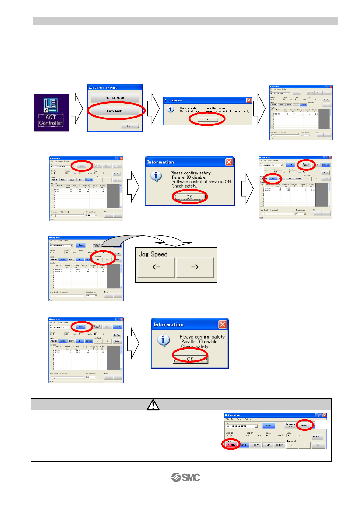
After turning on the controller power supply, start up the ACT Controller setting soft ware.
Select “Easy Mode” Select “OK”
(3) JOG Drive
a. Driving preparation : Servo On → Return to ORIG
Select “Monitor” Select “OK” (1)”SVRE” lighting is confirmed
b.JOG Drive (2) Select “Return to ORIG”
Clicking arrow button→Operation
“S” Direction ”O” Direction
c.Driving stop : Servo Off
Select “Test” Select “OK”
Caution
If an alarm is generated
(1) When ”ALARM” is generated, release it by selecting (2) Reset.
In the case of an alarm code that cannot be released with
“Reset”, turn the power supply OFF and ON again.
Note) For details of alarm codes, refer to the Controller Operation Manual.
(1)
(1)
(2)
(2)
- 7 -
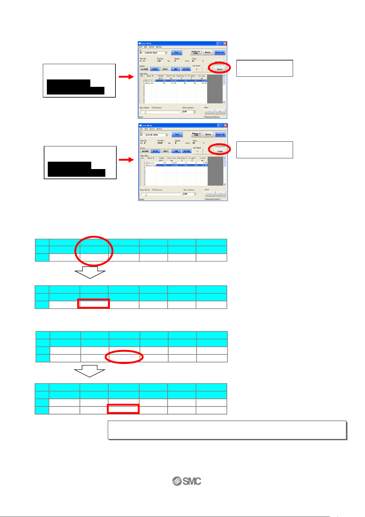
(4) TEST Drive / Step No.0 → No.1 → No.0・・・
a. Driving preparation : Servo On → Return to ORIG / Refer to “3.JOG Drive”.
b.TEST Drive
“Step No.0” Operation
→ Operation
“Step No.1” Operation
→ Operation
c.Driving stop : Servo Off / Refer to “3.JOG Drive”.
(5) Step data change
Ex) “Step No.0” / Positioning operation
Change of positioning speedP
Position: 24mm → 20mm Speed: 200°/s→50°/s
Input ”50”
Step Data
No. Move M Speed Position Pushing F TriggLV In pos
°/s ° % % °
0 ABS 50 0.00 0 0 0.50
Ex) “Step No.1” / Positioning operation
Change of pushing start position
Position: 180°→ 90°
Input ”90”
Step Data
No. Move M Speed Position Pushing F TriggLV In pos
°/s ° % % °
0 ABS 50 0.00 0 0 0.50
1 ABS 200 90.00 0 0 0.50
(6) Controller setting software screen explanation
Refer to the “Help / Easy mode” menu in the “ACT Controller” setting software.
Step Data
No. Move M Speed Position Pushing F TriggLV In pos
°/s ° % % °
0 ABS 50 0.00 0 0 0.50
1 ABS 200 180.00 0 0 0.50
Step Data
No. Move M Speed Position Pushing F TriggLV In pos
°/s ° % % °
0 ABS 200 0.00 0 0 0.50
Procedure 1:
Select “Step No.0”
You can select
anywhere in the row
Procedure 2:
Select “Drive”
Procedure 3:
Select “Step No.1”
You can select
anywhere in the row
Procedure 4:
Select “Drive”
For details of operation, and relationship between operation procedure and input/
output signals, refer to “3.3 Step Data setting method” p. 21 to 30.
- 8 -
1.3 Teaching box
(1) Name
(2) JOG Drive
Select “JOG” Method of ending “JOG Drive”
Press the (3)SET key
(3) TEST Drive / Step No.0 → No.1 → No.0・・・
Select “TEST”
Press the (3)SET key
Method of ending “TEST Drive”
It is the same as the Method
of ending “JOG Drive”
アラーム
ALARM
ジョグ
JOG
設定
SETTING
テスト
TEST
モニタ
MONITOR
データ
DATA
アラーム
ALARM
ジョグ
JOG
設定
SETTING
テスト
TEST
モニタ
MONITOR
データ
DATA
(1) Number key
(4) Up and down,
right and left key
(3)SET key
(2) JOG key
(5)MENU key
The
power
supply
is turned
on.
EXT Inp OFF:YES
Press the (3)SET key
↓
Servo ON,Ready?:YES
Press the (3)SET key
↓
RTN ORIG:Start
Press the (3)SET key
↓
JOG 1
RTN ORIG Done
“JOG±”:Move
Posn 123.45°
Operates by (2) JOG key
JOG+: “S” Direction
JOG-: ”O” Direction
Press the (5)MENU key
↓
Check 1
EXT Inp ON
OK
Press the (3)SET key
アラーム
ALARM
ジョグ
JOG
設定
SETTING
テスト
TEST
モニタ
MONITOR
データ
DATA
アラーム
ALARM
ジョグ
JOG
設定
SETTING
テスト
TEST
モニタ
MONITOR
データ
DATA
The
power
supply
is turned
on.
EXT Inp OFF:YES
Press the (3)SET key
↓
Servo ON,Ready?:YES
Press the (3)SET key
↓
RTN ORIG:Start
Press the (3)SET key
↓
Test 1
Step No. 0
Test Start
Posn 0.00°
<1: Drive test >
Press the
(4)Down key
Test 1
Step No. 0
Test Start
Posn 0.00°
Press the (3)SET key
↓
Step No.0
Test Complete
↓
<2: Select Step No.>
Press the
(4)Up key
Test 1
Step No. 1
Test Start
Posn 180.00°
Press the (1)Number key”1”
Press the (3)SET key
↓
Repeat <1: Drive test>
AX
IS.
AX
IS.
AX
IS.
AX
IS.
AX
IS.
- 9 -
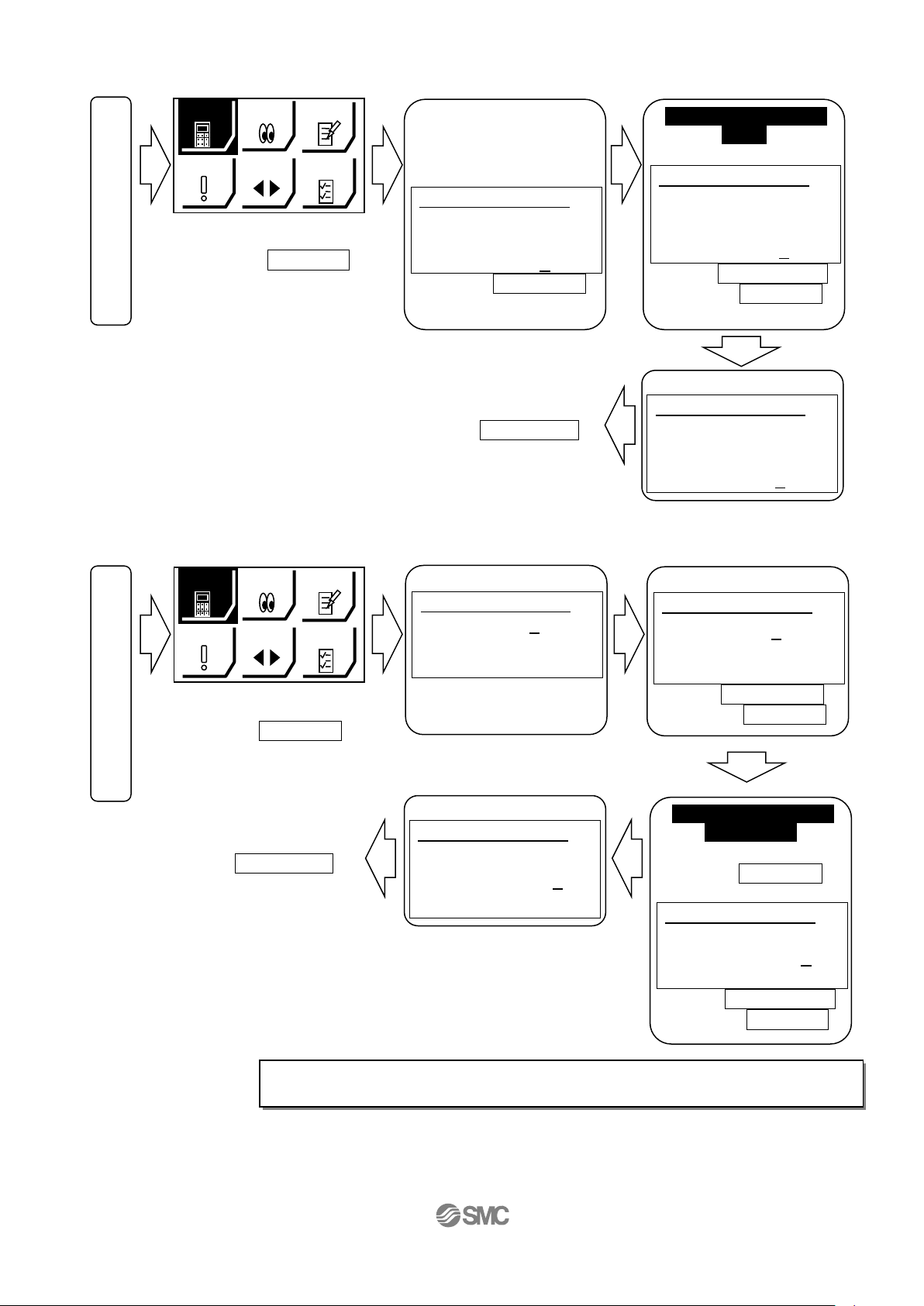
(4) Step data change
“Step No.0” / Positioning operation
Select “DATA”
Press the (3)SET key
Method of ending “DATA”
Press the (5)MENU key
“Step No.1” / Positioning operation
Select “DATA”
Press the (3)SET key
Method of ending “DATA”
Press the (5)MENU key
(5) Teaching box detailed explanation
Please refer to the teaching box manual.
アラーム
ALARM
ジョグ
JOG
設定
SETTING
テスト
TEST
モニタ
MONITOR
データ
DATA
The
power
supply
is turned
on.
アラーム
ALARM
ジョグ
JOG
設定
SETTING
テスト
TEST
モニタ
MONITOR
データ
DATA
The
power
supply
is turned
on.
Change of positioning
start position
Posn:180°
→ 90°
Press the
(4)Down key
Select “Posn”
Step 1
Step No. 1
Posn 180.00°
Speed 200°/s
Press the (1)Number key”90”
Press the (3)SET key
Change of positioning
speed
Speed 200°/s
→
50°/s
Step 1
Step No. 0
Posn 0.00°
Speed 200°/s
Press the (1)Number key”50”
Press the (3)SET key
Screen showing the
actuator speed.of
200°/s
Step 1
Step No. 0
Posn 0 .00°
Speed 200°/s
Press the (4)Down key
Select “Speed”
Change “Step No.1”
Step 1
Step No. 1
Posn 0 .00°
Speed 50°/s
Press the (1)Number key”1”
Press the (3)SET key
“Step No.0”
Step 1
Step No. 0
Posn 0 .00°
Speed 50°/s
Select “Step No.”
AX
IS.
AX
IS.
AX
IS.
AX
IS.
AX
IS.
“Complete”
Step 1
Step No. 0
Posn 0 .00°
Speed 50°/s
“Complete”
Step 1
Step No. 1
Posn 90.00°
Speed 200°/s
For details of operation, and relationship between operation procedure and input/
output signals, refer to 3.3 “Step Data” setting method p. 21 to 30.
AX
IS.
AX
IS.
- 10 -
2. Electric Rotary Table /LER Series
2.1 LER Series( Basic ・ External stopper )
2.1.1 Specification
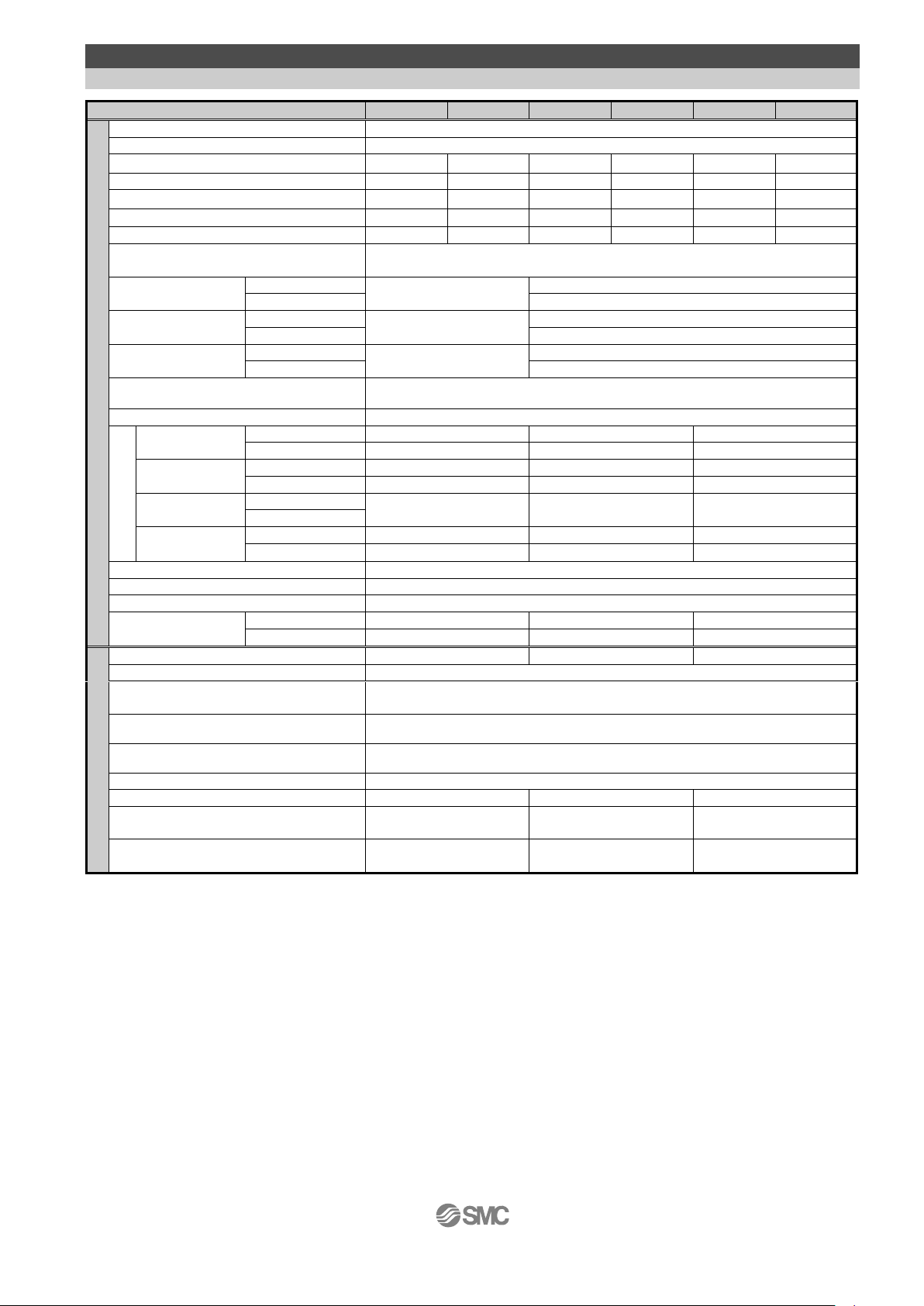
Model
LER*10K
LER*10J
LER*30K
LER*30J
LER*50K
LER*50J
Actuator
specification
/ Basic
Rotation Angle (°)
310
320
Gear rate(°)
8
12 8 12
7.5
12
Max. Rotation Torque(N・m)
0.32
0.22
1.2
0.8
10.0
6.6
Pushing Torque 40~50%(N・m)
Note 1) Note 3)
0.13~0.16
0.09~0.11
0.48~0.60
0.32~0.40
4.0~5.0
2.6~3.3
Max. Moment of
Inertia(kg・m2)
Note 2)
LECP6/1/MJ/JXC9
0.004
0.0018
0.035
0.015
0.13
0.05
LECPA
0.027
0.012
0.10
0.04
Rotation Speed(°/sec)
Note 2) Note 3)
20to280
30to420
20to280
30to420
20to280
30to420
Pushing Speed(°/sec)
20
30
20
30
20
30
Angular acceleration/
Angular deceleration(°/sec2)
Note 2)
3,000
Backlash(°)
Basic
± 0.3
± 0.2
High precision
± 0.1
Repeatability (°)
Basic
± 0.05
± 0.05
High precision
± 0.03
Lost motion (°)
Note 4)
Basic
0.3 or less
0.3 or less
High precision
0.2 or less
Impact resistance/vibration resistance
(m/sec2)
Note 5)
150/30
Actuation type
Worm gear and belt
Table allowable
load
Radial load
(N)
Basic
78
196
314
High precision
86
233
378
Thrust load
/Push(N)
Basic
78
363
451
High precision
107
398
517
Thrust load
/Pull(N)
Basic
74
197
296
High precision
Moment
(N・m)
Basic
2.4
5.3
9.7
High precision
2.9
6.4
12.0
Max. operating frequency(c.p.m)
60
Operating temperature range (oC)
5 to 40
Operating humidity range (%RH)
90 or less (No condensation)
Weight (kg)
Basic
0.49
1.1
2.2
High precision
0.52
1.2
2.4
External stopper
Rotation Angle (°)
(-2) with 1 Arm
180
(-3) with 2 Arms
90
Repeatability at the end (°)
±0.01
Range of external stopper(°)
±2
Weight
(kg)
(-2) with 1
Arm
Basic
0.55
1.2
2.5
High precision
0.61
1.4
2.7
(-3) with 2
Arms
Basic
0.57
1.2
2.6
High precision
0.63
1.4
2.8
Electric
specification
Motor size
□20
□28
□42
Motor
Step motor (Servo 24VDC)
Encoder
(Angular displacement sensor)
Incremental A/B phase (800 pulse/rotation)
Rated voltage(VDC)
24 ± 10%
Power consumption(W)
Note 6)
11
22
34
Standby power consumption when
operating(W)
Note 7)
7
12
13
Max.instantaneous
power consumption(W)
Note 8)
19
42
57
Note 1) Pushing Torque accuracy should be ±30%(F.S.) for LER10, ±25%(F.S.) for LER30, ±20%(F.S.) for LER50.
Note 2) The Angular acceleration, angular deceleration and angular speed may fluctuate due to variations in the moment of inertia.
Refer to the catalog.
Note 3) The speed and force may change depending on the cable length, load and mounting conditions.Furthemore, if the cable length
exceeds 5m then it will decrease by up to 10% for each 5m.(At 15m : Reduced by up to 20%)
Note 4) A reference value for correcting an error in reciprocal operation.
Note 5) Impact resistance: No malfunction occured when the rotary actuator was tested with a drop tester in both an axial direction and a
perpendicular direction to the lead screw. (The test was performed with the rotary actuator in the initial state)
Vibration resistance: No malfunction occured in a test ranging between 45 to 2000 Hz. Test was performed in both an axial direction
and a perpendicular direction to the lead screw.
(The test was performed with the rotary actuator in the initial state)
Note 6) The “Power consumption” (including the controller) is for when the actuator is operating.
Note 7) The “Standby power consumption when operating” (including the controller) is for when the actuator is stopped in the set
position during the operation, except for during the pushing operation.
Note 8) The “Momentary max.power consumption” (including the controller) is for when the actuator is operating.
This value can be used for the selection of the power supply.
- 11 -
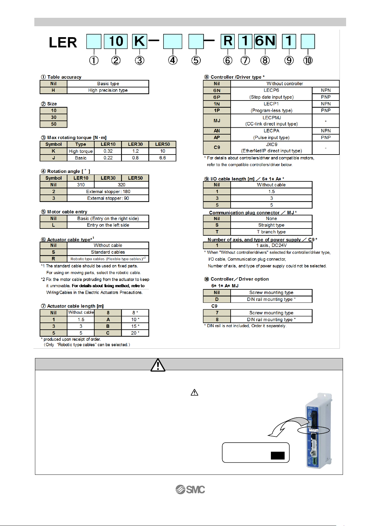
2.1.2 How to Order
Caution
The actuator body and controller are sold as a package.
If When only the actuator is purchased separately, confirm that the combination of the controller, which
you have and the actuator is compatible. / See 5.3 Caution (1) on p. 36
<Be sure to check the following before use.>
(1) Check that actuator label for model number.
This matches the controller.
(2) Check Parallel I/O configuration matches (NPN or PNP).
(1)
(2)
LER10K
NPN
- 12 -
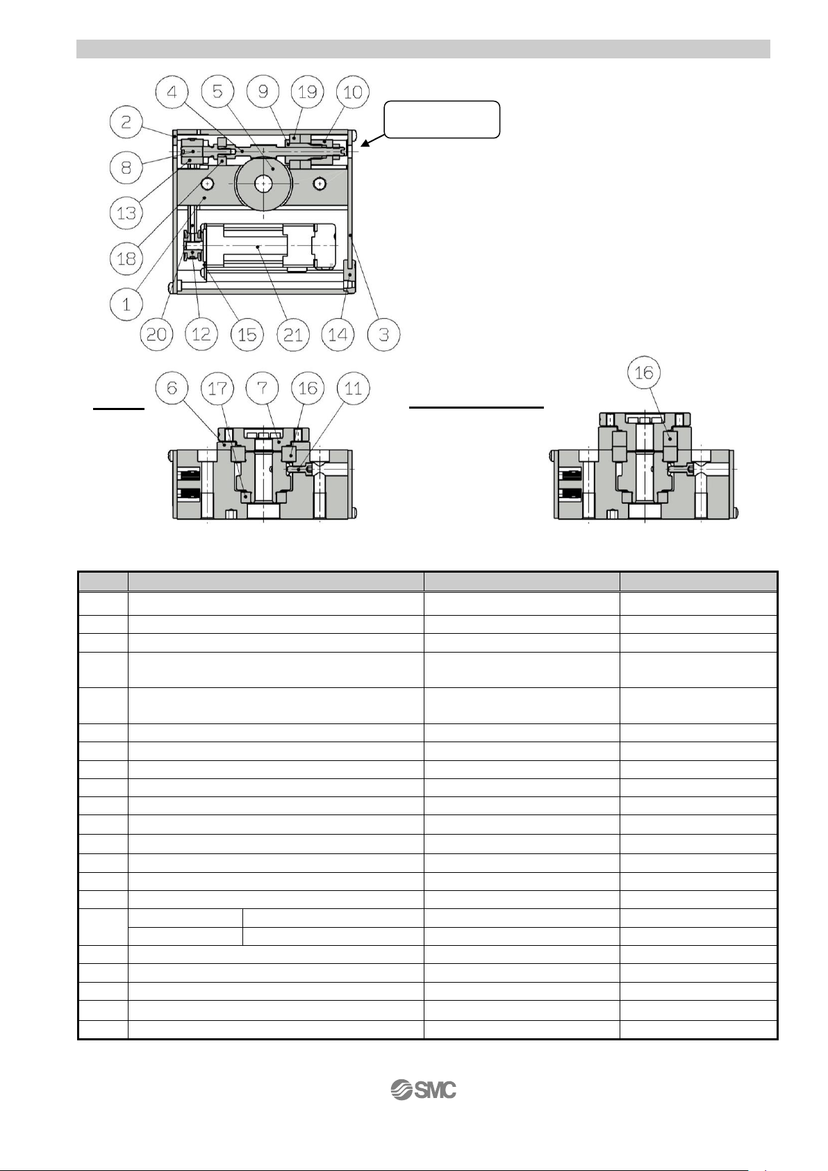
2.1.3 Construction
Parts list
No.
Part
Material
Remarks
1
Body
Aluminium alloy
Anodized
2
Side plate A
Aluminium alloy
Anodized
3
Side plate B
Aluminium alloy
Anodized
4
Worm screw
Stainless steel
Heat treated,
Specially treated
5
Worm wheel
Stainless steel
Heat treated,
Specially treated
6
Bearing cover
Aluminium alloy
Anodized
7
Table
Aluminium alloy
Anodized
8
Joint
Stainless steel
9
Bearing holder
Aluminium alloy
10
Bearing retainer
Aluminium alloy
11
Starting point bolt
Carbon steel
12
Pulley A
Aluminium alloy
13
Pulley B
Aluminium alloy
14
Grommet
NBR
15
Motor plate
Carbon steel
16
Basic
Deep groove ball bearing
-
High precision
Special ball bearing
-
17
Deep groove ball bearing
-
18
Deep groove ball bearing
-
19
Deep groove ball bearing
-
20
Belt
-
21
Step motor (Servo/24VDC)
-
Basic
High precision
Manual override
/Both sides
- 13 -
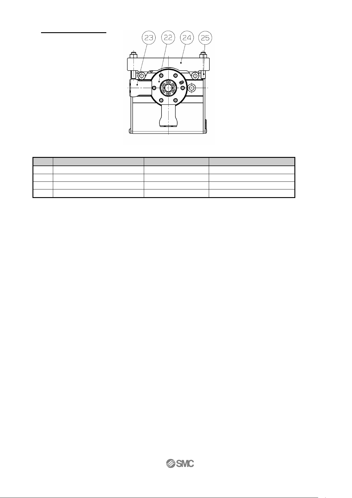
Parts list
No.
Part
Material
Remarks
22
Table
Aluminium alloy
Anodized
23
Arm
Carbon steel
Nickel plated
24
Holder
Aluminium alloy
Anodized
25
Adjustment bolt
Carbon steel
Chromating
External stopper
- 14 -
2.2 LER Series( Continuous rotation / 360° type )
2.2.1 Specification
Model
LER*10K
LER*10J
LER*30K
LER*30J
LER*50K
LER*50J
Actuator
specifi
cation
/ 360°type
Rotation Angle (°)
) Note 9)
360
Angle range (°)
Note 9)
±20000000
Max. Rotation Torque(N・m)
0.32
0.22
1.2
0.8
10.0
6.6
Pushing Torque 40~50%(N・m)
Note 1) Note 3)
0.13~0.16
0.09~0.11
0.48~0.60
0.32~0.40
4.0~5.0
2.6~3.3
Max. Moment of Inertia(kg・m2)
Note 2)
0.004
0.0018
0.035
0.015
0.13
0.05
Rotation Speed(°/sec)
Note 2) Note 3)
20to280
30to420
20to280
30to420
20to280
30to420
Pushing Speed(°/sec)
20
30
20
30
20
30
Angular acceleration/
Angular deceleration(°/sec2)
Note 2)
3,000
Backlash(°)
Basic
± 0.3
± 0.2
High precision
± 0.1
Repeatability (°)
Basic
± 0.05
± 0.05
High precision
± 0.03
Lost motion (°)
Note 4)
Basic
0.3 or less
0.3 or less
High precision
0.2 or less
Impact resistance/vibration resistance
(m/sec2)
Note 5)
150/30
Actuation type
Worm gear and belt
Table
allowable load
Radial load
(N)
Basic
78
196
314
High precision
86
233
378
Thrust load
/Push(N)
Basic
78
363
451
High precision
107
398
517
Thrust load
/Pull(N)
Basic
74
197
296
High precision
Moment
(N・m)
Basic
2.4
5.3
9.7
High precision
2.9
6.4
12.0
Max. operating frequency(c.p.m)
60
Operating temperature range (oC)
5 to 40
Operating humidity range (%RH)
90 or less (No condensation)
Weight (kg)
Basic
0.51
1.2
2.3
High precision
0.55
1.3
2.5
Electric
specification
Motor size
□20
□28
□42
Motor
Step motor (Servo 24VDC)
Encoder
(Angular displacement sensor)
Incremental A/B phase (800 pulse/rotation)
Proximity sensor (for Return to original
position)/ Input circuit
2 wire
Proximity sensor (for Return to original
position)/ Input number
1 outputs
Rated voltage(VDC)
24 ± 10%
Power consumption(W)
Note 6)
11
22
34
Standby power consumption when
operating(W)
Note 7)
7
12
13
Max.instantaneous
power consumption(W)
Note 8)
19
42
57
Note 1) Pushing Torque accuracy should be ±30%(F.S.) for LER10, ±25%(F.S.) for LER30, ±20%(F.S.) for LER50.
Note 2) The Angular acceleration, angular deceleration and angular speed may fluctuate due to variations in the moment of inertia.
Refer to the catalog.
Note 3) The speed and force may change depending on the cable length, load and mounting conditions.Furthermore, if the
cable length exceeds 5m then it will decrease by up to 10% for each 5m.(At 15m : Reduced by up to 20%)
Note 4) A reference value for correcting an error in reciprocal operation.
Note 5) Impact resistance: No malfunction occured when the rotary actuator was tested with a drop tester in both an axial
direction and a perpendicular direction to the lead screw.
(The test was performed with the rotary actuator in the initial state)
Vibration resistance: No malfunction occured in a test ranging between 45 to 2000 Hz. Test was performed in both an
axial direction and a perpendicular direction to the lead screw.
(The test was performed with the rotary actuator in the initial state)
Note 6) The “Power consumption” (including the controller) is for when the actuator is operating.
Note 7) The “Standby power consumption when operating” (including the controller) is for when the actuator is stopped
in the set position during the operation, except for during the pushing operation.
Note 8) The “Momentary max.power consumption” (including the controller) is for when the actuator is operating.
This value can be used for the selection of the power supply.
Note 9) The Monitor angle is reset to 0o every 360o. Select INC (Relative) for setting the angle (position).
If setting the angle above 360o with ABS (Absolute), the actuator will not operate correctly.

- 15 -
2.2.2 How to Order
Caution
The actuator body and controller are sold as a package.
If When only the actuator is purchased separately, confirm that the combination of the controller, which
you have and the actuator is compatible. / See 5.3 Caution (1) on p. 36
<Be sure to check the following before use.>
(3) Check that actuator label for model number.
This matches the controller.
(4) Check Parallel I/O configuration matches (NPN or PNP).
(1)
(2)
LER10K-1
NPN

- 16 -
2.2.3 Construction
No.
Part
Material
Remarks
1
Body
Aluminium alloy
Anodized
2
Side plate A
Aluminium alloy
Anodized
3
Side plate B
Aluminium alloy
Anodized
4
Worm screw
Stainless steel
Heat treated,
Specially treated
5
Worm wheel
Stainless steel
Heat treated,
Specially treated
6
Bearing cover
Aluminium alloy
Anodized
7
Table
Aluminium alloy
Anodized
8
Joint
Stainless steel
9
Bearing holder
Aluminium alloy
10
Bearing retainer
Aluminium alloy
11
Pulley A
Aluminium alloy
12
Pulley B
Aluminium alloy
13
Grommet
NBR
14
Motor plate
Carbon steel
15
Basic
Deep groove ball bearing
-
High precision
Special ball bearing
-
16
Deep groove ball bearing
-
17
Deep groove ball bearing
-
18
Deep groove ball bearing
-
19
Belt
-
20
Step motor (Servo/24VDC)
-
21
Proximity dog
Stainless steel
22
Sensor holder
Carbon steel
Chromating
23
Sensor holder spacer
Aluminium alloy
Anodized
(high precision type only)
24
Square nut
Aluminium alloy
25
Proximity sensor assembly
-
Basic
High precision
Parts list
Manual override
/Both sides

- 17 -
or
Communication
cable
PC
Conversion
unit
PLC
Power supply
DC24V
USB cable
(A-miniB type)
●Controller
位置 速度
100 500
200
1000
50
200
1
2
3
テスト
テスト
テスト
現在位置
120.3
現在速度
200
mm
mm/s
動作中
アラーム
モニタ
設定
位置 速度
100 500
200
1000
50
200
1
2
3
テスト
テスト
テスト
現在位置
120.3
現在速度
200
mm
mm/s
動作中
アラーム
モニタ
設定
●Controller setting kit
(Controller setting software
Communication cable,
Conversion unit and
USB cable are included.)
Part No:LEC-W2
Controller setting
software
Motor cable
●Actuator cable
Part No:
・LE-CP- *-*
(Robotic type cable)
・LE-CP- *S-*
(Standard cable)
3. Product Outline
3.1 System construction
※ When the controller setting software/version is below 1.1, the display unit is distance (mm), but the
product recognizes it as an angle (°). To upgrade the software, please go to the operation manual
page of the SMC website. http://www.smcworld.com/
Warning
Refer to the operation manual of the LEC (controller) for detailed wiring.
/See 4 Wiring of cables on p.29.
Communication cable is to be connected to PC by USB cable through conversion unit.
And do not connect teaching box to PC.
Use only specified cables otherwise there maybe fire risk and damage.
The actuator body and controller are sold as a package.
If When only the actuator is purchased seperately, confirm that the combination
of the controller, which you have and the actuator is compatable.
/ See 5.3 Caution (1) on p. 36
<Be sure to check the following before use.>
(1) Check that actuator label for model number.
This matches the controller.
(2) Check Parallel I/O configuration matches (NPN or PNP).
●I/O cable
Part No:LEC-CN5-
●Teaching box
(with 3m cable)
Part No:LEC-T1-3EG
Power supply plug
<Applicable cable size>
AWG20 (0.5mm2)
To CN5
●Electric Rotary Table
Option
To CN4
To CN1
To CN2
To CN3
Power supply
DC24V
To CN4
(1)
(2)
LER10K
NPN
Note 1)
Note 1)
Note 1): These items are included when it is selected
by ordering code.
Note 2): When conformity to UL is required, the
electric actuator and controller should
be used with a UL1310 Class 2 power
supply.
Note 2)
Note 1)
Note 2)

- 18 -
3.2 Setting Function
Refer to the operation manual of the cotroller (LEC series) for details of the setting function.
Easy Mode for simple setting
>Select “Easy mode” for instant operation
Controller setting software
Setting and operation, such as the step data setting, test drive and JOG / fixed-distance moving, can
be performed on the same page.
Teaching box
Setting and operation by the simple screen without scrolling.
Select function by the iconized menu at the first page.
Step data setting and monitoring at the second page.
Data Axis 1
Step No. 0
Posn 123.45mm
Force 30%
It can be registered by “SET”
after entering the values.
Operation status can be
checked
1st screen
2nd screen
2nd screen
Example of setting the step data
Example of checking the operation status
1st screen
Monitor Axis 1
Step No. 1
Posn 12.34mm
Force 50%
Positioning data setting
Fixed distance
moving
Speed setting of JOG /
fixed distance
JOG moving
Start testing
アラーム
ALARM
ジョグ
JOG
設定
SETTING
テスト
TEST
モニタ
MONITOR
データ
DATA
アラーム
ALARM
ジョグ
JOG
設定
SETTING
テスト
TEST
モニタ
MONITOR
データ
DATA

- 19 -
Normal mode for the detailed setting
>Select “Normal mode” if the detailed setting are necessary.
Step data can be set in detail.
Parameters can be set.
Signals and terminal condition can be monitored.
JOG and fixed distance movement, return to origin position, test operation and testing of compulsory
output can be done.
Controller setting soft ware
Every function, step data, parameter, monitor and teaching are indicated in a different window.
Teaching box
The data in the controller can be saved / forwarded in this teaching box.
Continuous test operation can be made after specifying five step data.

- 20 -
Controlled items
PC: Controllersetting sftware
TB: Teaching box
O: Available function
X: Not available function
Function
Content
Easy
mode
Normal
mode
PC
TB
PC/TB
Step data
(Except)
Movement method
Can be selected of absolute / relative position move
○ × ○
Speed
Can be set in units of 1°/s.
○ ○ ○
Position
Can be set in units of 0.01°.
○ ○ ○
Acceleration
Deceleration
Can be set in units of 1°/s2.
○ ○ ○
Pushing force
Can be set in units of 1%. /
In case of positioning operation: Set to 0%.
○ ○ ○
Trigger LV
Trigger LV of target pushing force when pushing operation:
Can be set in units of 1%.
○ × ○
Pushing speed
Can be set in units of 1°/s.
○ × ○
Moving force
100%
○ × ○
Area output
Can be set in units of 0.01°.
○ × ○
In position
During positioning operation: Width to the target position. It
should be set to 0.5° ro more.
During pushing operation: How much it moves during
pushing.
○ × ○
Parameter
(Except)
Stroke(+)
+ side limit of position.
(
Can be set in units of 0.01°)
× × ○
Stroke(-)
- side limit of position.
(
Can be set in units of 0.01°).
× × ○
ORIG direction
Direction of the return to the original position can be set
× × ○
ORIG speed
Speed when returning to the original position can be set.
× × ○
ORIG ACC
Acceleration when returning to origin can be set.
× × ○
Test
JOG
It can make continuous operation at the set speed while the
switch is being pressed
○ ○ ○
MOVE
It can make test operation at the set distance and speed from
the current position when the switch is pressed.
○ × ○
Rerurn to ORIG
Test of return to origin can be done.
○ ○ ○
Test drive
The operation of the specified step data can be tested.
○
○
○
(Continuous
operation)
Force output
ON/OFF of the output terminal can be tested.
× × ○
Monitor
DRV mon
Current position, current speed, current force and the
specified step data No. can be monitored.
○ ○ ○
In/Out mon
Current ON/OFF status of the input and output terminal can
be monitored.
× × ○
ALM
Status
The alarm currently being gen erated can be confirmed, and
be reset.
○ ○ ○
ALM Log record
The alam generated in the past can be confirmed.
× × ○
File
Save - Load
The step data and parameter of the objective controller can
be saved, forwarded and deleted.
× × ○
Other
Language
Language can be changed to Japanese / English.
○
*3 ○ *2
○
*2 *3
*1 Every parameter is set to the recommended condition before shipment from the factory. Only change the setting of the items which
require adjustment.
*2 Teaching box: In the Normal mode the teaching box can be set to work in English or Japanese.
*3 Controller setting software: Can be installed by selecting English version or Japanese version.

- 21 -
3.3 Step data setting method
Refer to the operation manual of the controller (LEC series) for details.
This operation manual specifies the electric rotary actuator, if an actuator other than the electric rotary
actuator is used, refer to the operation manual of each type of actuator and controller (LEC series)
regarding the description of step data.
Caution
The actuator body and controller are sold as a package.
If When only the actuator is purchased separately, confirm that the combination of the controller, which
you have and the actuator is compatible. / See 5.3 Caution (1) on p. 36
<Be sure to check the following before use.>
(1) Check that actuator label for model number.
This matches the controller.
(2) Check Parallel I/O configuration matches (NPN or PNP).
Positioning operation
In the positioning operation, the electric rotary actuator moves to and stops at the target position.
The following image shows the setting items and operation.
<Confirmation of reaching the target position during the positioning operation>
When the table of the rotary actuator reaches the range of the target position, the “target position
reaching signal” 【INP】 (in position) is outputted.
When the table of the rotary actuator enters the range of 【In position】, the INP output signal turns
on.
Caution
When the table is to be stopped by an external object, utilize the “pushing operation”.
If the product is used in the positioning operation, there may be galling or other problems when it
comes into contact with the external object.
Note) When it is not possible to operate the table, move it with manual override screws.
/ See 6.2 Caution (5) on p. 40
and 6.3 Caution (4) on p. 40
(1)
(2)
LER10K
NPN
Speed
Acceleration
Deceleration
Speed
ON
INP output
Position
ON
OFF
In pos

- 22 -
<Items and set values in positioning operation>
Step No. 0: Positioning operation
a b c d e f g h i j k
No. Move M Speed Position Accel Decel PushingF TriggerLV PushingSp MovingF Area1 Area2 In pos
°/s ° °/s^2 °/s^2 % % °/s % ° ° °
0 ABS 200 0.00 3000 3000 0 0 0 100 20.00 40.00 0.50
1 ABS 200 180.00 3000 3000 50 50 30 100 179.00 181.00 5.00
【◎】 Need to be set ・ 【○】Need to be adjusted as required
【X】 Not used. Items don't need to be changed in positioning operation.
a <◎ Movement MOD> When the absolute position is required, set Absolute
When the relative position is required, set Relative
⇒ Absolute: Distance from the origin position. / General setting method
Relative: Feed from the current position. / This is used when simplified data.
b <◎ Speed> Transfer speed to the target position.
c <◎ Position> Target position.
d <○ Acceleration>
The parameter which defines how rapidly the actuator reaches the speed set in
b
The higher the set value, the faster it it reaches the speed set in
b
.
e <○ Deceleration> The parameter which defines how rapidly the actuator comes to stop.
The higher the set value, the quicker it stops.
f <◎ Pushing force> Set 0.
(If values other than 0 set, the operation will be changed to the pushing operation.)
g <X Trigger LV> h <X Pushing speed>
i <○ Moving force> Max. force at the positioning operation.
The force is automatically adjusted corresponding to the load.
/See 6.3 Caution (2) on p. 40
j <○ Area1,Area2> This is the condition that turns on the AREA output signal.
The setting condition should be Area 1<Area 2.
It is possible to set at Relative operation too.
The position will be Absolute (position from the origin).
Example) In case of Step no.0
【AREA】 output signal is outputted between Area 1:20 and Area 2:40.
k <○ In position> This is the condition that turns on the INP (in position) output signal.
⇒ When the electric rotary actuator reaches the range of the target position, the
INP output signal is output.
When the electric actuator enters the range of [in position], the INP output signal
turns on.
When it is necessary to output the target position reaching signal earlier, make
the value larger.
Note) Default:Set the value more than 【0.50】.
Example) In case of Step no.0
Position:0 + In position:0.5 = 【INP】 is outputted from the value of 0.5.

- 23 -
Pushing operation
The table move to the target position and hold a work piece with the set pushing force.
The figure shows setting items and operation.The setting items and values are described below.
< Confirmation of reaching the target value during the pushing operation>
The “target position reaching signal” INP (in position) is generated when the target pushing force
(Trigger LV) is achieved.
Also, if the actual pushing force exceeds the Trigger LV, the INP signal is turned on.
Caution
When the table is to be stopped by an external object, utilize the “pushing operation”.
If the product is used in the positioning operation, there may be galling or other problems when it
comes into contact with the external object.
Note) When it is not possible to operate the table, move it with manual override screws.
/ See 6.2 Caution (5) on p. 40
and 6.3 Caution (4) on p. 40
Speed
Speed
Acceleration
Deceleration
Position
Pushing speed
In pos
Force
Pushing force
Trigger LV
INP output

- 24 -
<Items and setting values of pushing operation>
Step no. 1: Pushing operation
a b c d e f g h i j k
No. Move M Speed Position Accel Decel PushingF TriggerLV PushingSp MovingF Area1 Area2 In pos
°/s ° °/s^2 °/s^2 % % °/s % ° ° °
0 ABS 200 0.00 3000 3000 0 0 0 100 20.00 40.00 0.50
1 ABS 200 180.00 3000 3000 50 50 30 100 179.00 181.00 5.00
【◎】 Need to be set ・ 【○】Need to be adjusted as required
a <◎ Movement MOD> When the absolute position is required, set Absolute
When the relative position is required, set Relative
⇒ Absolute : Distance from the origin position.
Relative : Feed from the current position
b <◎ Speed> Transferring speed to the target position.
c <◎ Position> Target position.
Note) When the table is to be stopped by an external object, set the product to a
position of at least 1 degrees away from the work piece. (This position is
referred to as the pushing start position). / See 6.3 Caution (5) on p. 41
d <○ Acceleration>
The parameter which defines how rapidly the actuator reaches the speed set in
b
The higher the set value, the faster it it reaches the speed set in
b
.
e <○ Deceleration> The parameter which defines how rapidly the actuator comes to stop.
The higher the set value, the quicker it stops.
f <◎ Pushing force> Pushing force ratio is defined. Note) 40% to 50%
g <◎ Trigger LV> The condition at which INP output signal is turned on.
Set it at the value equivalent to the pushing force
/ See 6.3 Caution (3) on p. 40
⇒ The INP output signal is given when the target force (Trigger LV) is achieved.
The INP output signal is turned on when the generated force exceeds the value.
h <◎ Pushing speed> The pushing speed
⇒ Set the speed in the following range. If the speed is too high, the actuator or
workpiece can be damaged by the impact.
Note) LER*K series: 20 °/sec , LER*J series: 30 °/sec
i <○ Moving force> The upper force limit for the pushing operation starting position.
The force is automatically adjusted corresponding to the load.
/See 6.3 Caution (2) on p. 40
j <○ Area1,Area2> This is the condition that turns on the AREA output signal.
The setting condition should be Area 1<Area 2.
It is possible to set at Relative operation.
The position will be Absolute (position from the origin).
k <◎ In position> The transfer distance (relative value) when pushing
If the transferred distance exceeds the setting, it stops even if it is not pushing.
If the transfer distance is exceeded, the INP output signal will not be turned on.
(incomplete pushing)
Example) In case of Step no.1
Position: 180 + positioning width: 5 =185 (
The position where the incomplete pushing is detected.
)

- 25 -
Example of step data entry (1)
< Positioning operation - 【INP】output signal, 【AREA】output signal >
a b c d e f g h i j k
No. Move M Speed Position Accel Decel PushingF TriggerLV PushingSp MovingF Area1 Area2 In pos
°/s ° °/s^2 °/s^2 % % °/s % ° ° °
0 ABS 200 0.00 3000 3000 0 0 0 100 20.00 40.00 0.50
・Step data no.0 : Positioning operation (It moves from Position:180[°] to Position:0[°])
Condition 1) The 【AREA】output signal is not used.
【IN P 】
O utput signal
200
0
S peed[°/s]
ON
OFF
b
P osition[°]
c
180 160 140 120 100 80 60 40 20 0
S troke [°]
In pos[°]
k
-0.5
0.5
(【IN P 】
O utput condition)
180°
90°
0°
270°
Condition 2) The 【AREA】output signal is used.
*The 【AREA】output signal is a signal output when the rod traverses through a certain range (The step
data: Area 2 from Area 1).
This feature is useful when an output to check the rod position at intermediate stroke is required.
200
0
S peed[°/s]
ON
OFFONOFF
b
A rea2[°]
j
A rea1[°]
j
P osition[°]
c
180 160 140 120 100 80 60 40 20 0
S troke [°]
-0.5
0.5
90°
180°
0°
270°
40°
20°
【IN P 】
O utput signal
【A R E A 】
O utput signal
In pos[°]
k
(【IN P 】
O utput condition)
The 【INP】output signal is turned
on from
0[°] + 0.5[°] = 0.5[°]
・ The 【 AREA】 output signal is
turned on from Area 1:20[°]
between Area 2:40[°].
・ The 【 INP 】 output signal is
turned on from
0[°] + 0.5[°] = 0.5[°]

- 26 -
Example of step data entry (2)
< Pushing operation - 【INP】output signal, 【AREA】output signal >
a b c d e f g h i j k
No. Move M Speed Position Accel Decel PushingF TriggerLV PushingSp MovingF Area1 Area2 In pos
°/s ° °/s^2 °/s^2 % % °/s % ° ° °
0 ABS 200 40.00 3000 3000 50 40 30 100 0.00 60.00 50.00
・Step data no.0 : Positioning operation. (It moves to End limit after it moves from 180° to 40°.)
Condition 1) The 【AREA】output signal is not used.
180 160 140 120 100 80 60 40 20 0 -10
S troke [°]
30
0
S peed[°/s]
ON
OFFb200500
P ushingF [% ]
f
40
g
TriggerLV [% ]
P osition[°]
c
In pos[°]
k
P ushingS p[°/s]
h
90°
180°
0°
270°
-10°
40°
【IN P 】
O utput signal
(【IN P 】
O utput condition)
Condition 2) The 【AREA】output signal is used.
* The 【AREA】output signal is a signal output when the rod traverses through a certain range (The
step data: Area 2 from Area 1).
This feature is useful when an output to check the rod position at intermediate stroke is required.
30
0ONOFF
200
50040ONOFF
180 160 140 120 100 80 60 40 20 0 -10
S troke [°]
90°
180°
0°
270°
-10°
40°
P ushingF [% ]
f
【IN P 】
O utput signal
【A R EA 】
O utput signal
S peed[°/s]
b
P osition[°]
c
g
Trigg erLV [% ]
In pos[°]
k
P ushingS p[°/s]
h
(【IN P 】
O utput cond ition)
A rea1[°]
j
A rea2[°]
j
・ The 【 INP 】 output signal is
turned on when trigger LV :
40[%] is exceeded.
/See 6.3
caution(3) on p.36
・The 【AREA】 output signal is
turned on from Area 1:0[°]
between Area 2:60[°].
・ The 【 INP 】 output signal is
turned on when trigger LV :
40[%] is exceeded.

- 27 -
Example of step data entry (3)
< Pushing operation - In position >
a b c d e f g h i j k
No. Move M Speed Position Accel Decel PushingF TriggerLV PushingSp MovingF Area1 Area2 In pos
°/s ° °/s^2 °/s^2 % % °/s % ° ° °
0 ABS 200 60.00 3000 3000 50 40 30 100 20.00 60.00 40.00
・Step data no.0 : Pushing operation
("Pushing operation" is done during 40° after it moves from 100° to 60°.)
Condition 1) Length to work < In position
(Le ngth to w ork)
40
P osition[°]
c
100 80 60 40 20 0
S troke [°]
20
0°
100°
270°
90°
60°
180°
40°
W
In pos[°]
k
Condition 2) Length to work > In position
60
40
100 80 60 40 20 0
S troke [°]
0°
90°
60°
100°
180°
20°
270°
W
(Le ngth to w ork)
P osition[°]
c
In pos[°]
k
・ k In pos ≧ Length to work
・Actual force ≧ g TriggerLV
The 【INP】 output signal is
turned on
【INP】Output condition
・ k In pos < Length to work
・Actual force < g TriggerLV
The 【 INP】 output signal is
not turned on
The 【BUSY】 output signal is
turmed on
【INP】Output condition

- 28 -
Example of step data entry (4)
< Pushing operation – Driving starting position >
The pushing action is different and dependent upon the starting position and derection.
Confirm the position where the pushing operation starts.
a b c d e f g h i j k
No. Move M Speed Position Accel Decel PushingF TriggerLV PushingSp MovingF Area1 Area2 In pos
°/s ° °/s^2 °/s^2 % % °/s % ° ° °
0 ABS 200 100.00 3000 3000 0 0 0 100 0.00 0.00 0.50
1 ABS 200 0.00 3000 3000 0 0 0 100 0.00 0.00 0.50
2 ABS 200 40.00 3000 3000 50 40 30 100 20.00 40.00 20.00
Condition 1) In case the pushing operation is Step no.0 to Step no.2.
100 80 60 40 20 0
S troke [°]
0°
90°
100°
270°
180°
20°
40°
P osition[°]
c
In pos[°]
k
Condition 2) In case the pushing operation is Step no.1 to Step no.2.
100 80 60 40 20 0
S troke [°]
270°
0°
90°
60°
40°
180°
P osition[°]
c
In pos[°]
k
Caution
When the operation is discontinued by EMG-Stop or drive-stop
Drive-stop and the pushing operation is commanded just after restart, the moving direction depends
on the operation-starting position.
Attainment point: 20[°]
Attainment point: 60[°]

- 29 -
Operating procedure and input / output signals for each operation.
The input / output signal and the operation description for operating this electric actuator are as
follows.
1) Signals along with the operation procedures
In case the operation order is
1. Supply power to the motor 2. Return to origin 3.Step no. 1 4.Step no. 2 5.Cut power to the motor
Procedure
Input signal
Output signal to the input
signal
Operation description
1
SVON (Servo on) [●]
SVRE (Servo ready) [●]
Power is supplied to the
motor, and detection of
the magnetic pole position
starts. => Completion.
2
SETUP [●]
SETON [●]
INP (IN position) [●]
Returning to the origin
starts.
=>Completion.
3
IN0 [●]
IN1 [ ]
IN2 [ ]
IN3 [ ]
IN4 [ ]
IN5 [ ]
↓
DRIVE [●]⇒[ ]Note 3) 5)
OUT0 [●]
OUT1 [ ]
OUT2 [ ] Note 3)4)
OUT3 [ ]
OUT4 [ ]
OUT5 [ ]
↓
After reaching of target
position, INP [ ● ]
After stopping motion,
BUSY [ ]
Step no. 1 is selected,
and the operation starts.
⇒ Complete.
4
IN0 [ ]
IN1 [●]
IN2 [ ]
IN3 [ ]
IN4 [ ]
IN5 [ ]
↓
DRIVE [●]⇒[ ]Note 3) 5)
OUT0 [ ]
OUT1 [●]
OUT2 [ ] Note 3)4)
OUT3 [ ]
OUT4 [ ]
OUT5 [ ]
↓
After reaching of target
position, INP [ ● ]
After stopping motion,
BUSY [ ]
Select the step no. 2, and
the operation starts.
⇒ Complete.
5
SVON [ ]
SVRE [ ]
SETON [●] Note 2)
INP [●]
Power to the motor is cut.
Note 1) [●] means ON, [ ] means OFF.
Note 2) The origin has been recognized when the operation is repeated, so it can operate without the
procedure item 2.
Note 3) The “OUT*” signals are reset during the rising edge of the Drive signal. The “OUT*” signal
which follows the “IN*”signal are outputted at the falling edge of the "drive" signal.
Note 4) When the alarm is generated, the alarm group is displayed.
Please confirm the controller (LEC series) manual for a detailed content of the alarm.
Note 5) Leave an interval of 15ms (the recommendation is 30ms) or more between input signals and
maintain the state of the signal for 15ms (the recommendation is 30ms) or more, because
PLC processing delays and controller scanning delays can occur.

- 30 -
2)
Signals when stopped: In the event when “EMG” is used
The operating sequence is 1. “Stop” 2. Release the “Stop”
Procedure
Input signal
Output signal for the input
signal
Operation description
1
EMG: Not energizing
(TB / Stop switch: Locking
*ESTOP[ ]
SVRE [ ]
SETON [●]
Power to the motor is cut by the
“Stop “ command regardless of
whether it is operating or
stopping.
2
EMG: Energizing
(TB / Stop switch: Releasing
*ESTOP[●]
SVRE [●]
SETON [●] Note 2)
The stop is released.
Note 1) [●] means ON, [ ] means OFF. * means negative logic
Note 2) SETON signal does not change after releasing the “STOP”.
Note 3) If the stop is input from the EMG or RESET terminal or the stop-switch on the connected
Teaching Box during pushing operation,the actuator stop.
(“Busy”signal turns OFF) And if the actuator stop within the range of ”Position”± ”In pos”
defined in step data,output signal “INP” turns ON.
Continuous rotation / 360° type setting
1) Precautions for setting Continuous rotation / 360°type
(1) The Monitor angle will be reset to 0o every 360o.
(2) Select Relative for setting the angle (position).
If the setting angle is over 360o with ABS (Absolute), the actuator will not operate correctly.
(3) Please set the range of output signal “Area” to 0°-359.99°.
2) The actuator stopped in the middle of the stroke due to emergency stop or alarm.
If Relative is selected in the next step, movement to the correct position will not be available.
Restart operation after moving back to 0o position using the procedure below.
3) Setting range of continuous rotation
If the set range of continuous rotation exceeds +/-9999.99o, use the controller kit (LEC-W2).
Teaching box (LEC-T1) has a limit for the display angle.
(1) Controller setting kit / LEC-W2
Relative method ±20000000.00°(Approx. 55555 rotations)
(2) Teaching box / LEC-T1
Relative method ±9999.99°(Approx. 27 rotations)
4) Setting method of continuous rotating.
Following is setting of three continuous rotation without stopping.
Movement MOD [Relative] / [Position] 1080°
Moreover, when output signal “Area” is set, the signal will output three times in three rotations
because of the signal setting range 0°-359.99°.

- 31 -
3.4 Parameter setting method
Initial setting for the basic parameters
Refer to the controller’s (LEC series) operation manual for detail.
As the “basic parameter” is unique data of each actuator, if an actuator other than the rotary actuator is
used, refer to the operation manual of each actuator and the controller’s (LEC series) operation
manual for the basic parameter.
Note1) Become effective after restarting the controller.
<Return to origin>
Before the positioning and pushing operation, “return to origin” is necessary to establish the origin. The current
position value of the electric
rotary table
increases if the “S” to “O”
direction
(move in the CW direction).
(The table moving direction to be increased cannot be changed.)
1) Flow of retun to origin
Input origin signal ⇒ Move toward origin ⇒ Stop moving ⇒ Move to the opposite direction ⇒ Origin
Description (Extract)
Initial input value
Input range
Controller ID 1 1 to 64 Note 1)
IO pattern
1: 64
-
ACC/ DCC pattern
1:Trapezoid - motion
-
S-motion rate
0
-
Stroke (+)
1000.00
/ Basic ,External stopper(-2,3)
10000000.00 /360°type(-1)
-
Stroke (-)
-1000.00
/ Basic ,External stopper(-2,3)
-10000000.00 /360°type(-1)
-
Max speed
Max. speed of each
product
Step data input limit:
Max. speed of each product
Max ACC / DCC
3,000
Step data input limit: 3,000 at the maximum
Def In position
0.50
-
ORIG offset
0.00 / Basic,360°type(-1)
5.00/ External
stopper(-2,3)
-
Max force
50
Step data input limit: 40 to 50
Para protect
1:Common+StepDate
Changeable parameter
1: Common + StepData, 2: Common
Enable SW
2: Disable
Select 1:Enable or 2:Disable when using a
teaching box
Unit name
Part no. of each
product
Only the English characters and numbers are
changeable.
W-AREA1
0.00
-
W- AREA2
0.00
-
ORIG Correct
0.00
-
Sensor type
1
-
Option set1
0
-
Undefined parameter 11
0
-
Undefined parameter 12
0
-
Initial set value for the
electric rotary actuator
/ Basic ,External stopper(-2,3)
“O” to “S”
direction (CCW
direction)
Starting point bolt
End edge
(pushing)
Moving distance
5°
(Not changeable)
“S” to “O”
direction (CW
direction)
Proximity
sensor
center (sensor)
No movement
(Not changeable)
Monitor 0°
/ Basic
Monitor 5°
/ External stopper(-2,3)
Monitor 0°
/360°type(-1)
Initial set value for the
electric rotary actuator
/ 360° type (-1)

- 32 -
Initial setting for the ORIG parameters
Refer to the controller’s (LEC series) operation manual for detail.
As the “ORIG parameter” is unique data of each actuator, if an actuator other than the electric rotary
actuator is used, refer to the operation manual of each actuator and the controller’s (LEC series)
operation manual for the for the “ORIG parameters” .
Note1) Become effective after restarting the controller.
Note2) Return to origin cannot return while operating. / See 5.1 Caution (4) on p. 34
Note3) Setting Return to origin to the position of the proximity sensor is available only for 360° type.
3.Limit switch origin1[Sensor1] recognizes the sensor detection range as the origin.
While detecting the sensor, the rotary table rotates in the reverse direction in the sensor detection
range.
Description
(Extract)
Initial input value
Input range
ORIG direction
2:CCW
/ Basic ,External stopper(-2,3)
1:CW
/360° type (-1)
1:CW (“O” direction)
2:CCW (“S” direction)
Note 1)
ORIG mode
1:Stop
/ Basic ,External stopper(-2,3)
3:Sensor1
/360° type (-1)
1: Pushing origin operation[Stop] Note 3)
2:Limit switch origin[Sensor]
3: Limit switch origin1[Sensor1]
ORIG limit
100
0 / 40 to 100
Note 2)
ORIG time
100
-
ORIG speed
20 / LER*K
30 / LER*J
-
ORIG ACC/DEC
500
-
Creep speed
20 / LER*K
30 / LER*J
-
ORIG sensor
0:Disable
/ Basic ,External stopper(-2,3)
1: Contact a
/360° type (-1)
0:Disable
1: Contact a
2: Contact b
ORIG SW Dir
0
-
Undefined
parameter 21
0
-

- 33 -
4. Wiring of cables / Common precautions
Warning
1. Adjusting, mounting or wiring change should never be done before shutting off the power
supply to the product.
Electrical shock, malfunction and damaged can result.
2. Never disassemble the cable. Use only specified cables.
3. Never connect or disconnect the cable or connector with power on.
Caution
1. Wire the connector securely. Do not apply any voltage to the terminals other than those
specified in the product manual.
2. Wire the connector securely.
Check for correct connector wiring and polarity.
3. Take appropriate measures against noise.
Noise in a signal line may cause malfunction. As a countermeasure, separate high voltage and low
voltage cables, and shorten wiring lengths, etc.
4. Do not route wires and cables together with power or high voltage cables.
The product can malfunction due to interference of noise and surge voltage from power and high
voltage cables to the signal line. Route the wires of the product separately from power or high voltage
cables.
5. Take care that actuator movement does not catch cables.
6. Operate with cables secured. Avoid bending cables at sharp angles where they enter the product.
7. Avoid twisting, folding, rotating or applying an external force to the cable.
Risk of electric shock, wire break, contact failure and loss of control for the product can happen.
8. Fix the cable protruding from the product in place before using.
The motor and lock cables are not robotic type cables and can be damaged when moved. Therefore fix
the cables and the connectors (part “A” in figure below) when set up
9. Select “Robotic type cables” in case of inflecting actuator-cable repeatedly. And do not put
cables into a flexible moving tube with a radius smaller than the specified value. (Min. 50mm).
Risk of electric shock, wire break, contact failure and loss of control for the product can happen if
“Standard cables” are used in case of inflecting the cables repeatedly
10. Confirm proper wiring of the product.
Poor insulation (interference with other circuits, poor insulation between terminals and etc.) can apply
excessive voltage or current to the product causing damage.
11. The Speed / pushing force may vary, depending on the cable length, load and mounting
conditions etc..
If the cable length exceeds 5m, the speed / pushing force will be reduced by a maximum of 10% per
5m. (If cable length is 15m: Maximum 20% reduction.)
[Transportation]
Caution
1. Do not carry or swing the product by the motor or cable

- 34 -
5. Electric actuators / Common precautions
5.1 Design and selection
Warning
1. Be sure to read the Operation Manual (this manual and the one for the controller: LEC series).
Handling or usage/operation other than that specified in the Operation Manual may lead to breakage
and operation failure of the product.
Any damage attributed to the use beyond the specifications is not guaranteed.
2. There is a possibility of dangerous sudden action by the product if sliding parts of machinery
are twisted due to external forces etc.
In such cases, human injury may occur, such as by catching hands or feet in the machinery, or damage
to the machinery itself may occur. Design the machinery should be designed to avoid such dangers.
3. A protective cover is recommended to minimize the risk of personal injury.
If a driven object and moving parts of the product are in close proximity, personal injury may occur.
Design the system to avoid contact with the human body.
4. Securely tighten all stationary parts and connected parts so that they will not become loose.
When the product operates with high frequency or is installed where there is a lot of vibration, ensure
that all parts remain secure.
5. Consider a possible loss of power source.
Take measures to prevent injury and equipment damage even in the case of a power source failure.
6. Consider behavior of emergency stop of whole system.
Design the system so that human injury and/or damage to machinery and equipment will not be caused,
when it is stopped by a safety device for abnormal conditions such as a power outage or a manual
emergency stop of whole system.
7. Consider the action when operation is restarted after an emergency stop or abnormal stop of
whole system.
Design the system so that human injury or equipment damage will not occur upon restart of operation
of whole system.
8. Never disassemble or modify (including additional machining) the product.
An injury ro failure can result.
It will cause the loss of the product performance.
9. Do not use the stop signal, "EMG" of the controller and stop switch on the teaching box as the
emergency stop of system.
The stop signal, "EMG" of controller and the stop switch on the teaching box are for decelerating and
stopping the actuator.
Design the system with an emergency stop circuit which is applied relevant safety standard separately.
10. When using it for vertical application, it is necessary to build in a safety device.
The rod may fall due to the weight of work. The safety device should not interfere with normal operation
of the machine.
Caution
1. Operate within the limits of the maximum usable stoke.
The product will be damaged if it is used with the stroke which is over the maximum stroke. Refer to the
specifications of the product.
2. When the product repeatedly cycles with partial strokes, operate it at a full stroke at least once
a day or every 1000 strokes.
Otherwise, lubrication can run out.
3. Do not use the product in applications where excessive external force or impact force is applied
to it.
The product can be damaged. Each component that includes motor is made with accurate tolerance.
So even slightly deformed or miss-alignment of component may lead operation failure of the product.

- 35 -
4. Rerutning to origin cannot be done during the operation.
It cannot be done during positioning operation, pushing operation and pushing.
5. Refer to a common auto switch /matter (Best Pneumatics No 2) when an auto switch is built in
and used.
6. When conformity to UL is required, the electric actuator and controller should be used with a
UL1310 Class 2 power supply.
5.2 Mounting
Warning
1. Install and operate the product only after reading the Operation Manual carefully and under
standing its contents. Keep the manual in a safe place future reference.
2. Observe the tightening torque for screws.
Tighten the screws to the recommended torque for mounting the product.
3. Do not make any alterations to this product.
Alterations made to this product may lead to a loss of durability and damage to the product, which can
lead to human injury and damage to other equipment and machinery.
4. When using external guide, the guide axis should be parallel to the actuator axis.
There will be damage/excessive wear on the lead screw if the external guide is not parallel.
5. When an external guide is used, connect the moving parts of the product and the load in such a
way that there is no interference at any point within the stroke.
Do not scratch or dent the sliding parts of the product tube or piston rod etc., by striking or grasping
them with other objects. Components are manufactured to precise tolerances, so that even a slight
deformation may cause faulty operation.
6. Prevent the seizure of rotating parts.
Prevent the seizure of rotating parts (pins, etc.) by applying grease.
7. Do not use the product until you verify that the equipment can operate properly.
After mounting or repair, connect the power supply to the product and perform appropriate functional
inspections to check it is mounted properly.
8. At the overhang mounted impeller fixation
There is a possibility that the power at the bending moment damages the actuator when moving it at
high speed.
The support metal fittings that suppress the vibration of the main body of the actuator are installed.
Lower and use speed for the state that the actuator doesn't vibrate.
9. When attaching the product body or work piece, do not apply strong impact or large moment.
If an external force over the allowable moment is applied, it may cause looseness in the guide unit, an
increase in sliding resistance or other problems.
10. Maintenance space
Allow sufficient space for maintenance and inspection.

- 36 -
5.3 Handling
Warning
1. Do not touch the motor while in operation.
The surface temperature of the motor can increase to approx. 80oC due to operating conditions.
Energizing alone may also cause this temperature increase. As it may cause burns, do not touch the
motor when in operation.
2. If abnormal heating, smoking or fire, etc., occurs in the product, immediately shut off the power
supply.
3. Immediately stop operation if abnormal operation noise or vibration occurs.
If abnormal operation noise or vibration occurs, the product may have been mounted incorrectly.
Unless operation of the product is stopped for inspection, the product can be seriously damaged.
4. Never touch the rotating part of the motor or moving part of the actuator while in operation.
5. When installing, adjusting, inspecting or performing maintenance on the product, controller and related
equipment, be sure to shut off the power supply to them. Then, lock it so that no one other than the person
working can turn the power on, or implement measures such as a safety plug.
6.
In the case of the actuator that has a servo motor (24VDC), the “motor phase detection step" is
done by inputting the servo on signal just after the controller power is turned on.
The “motor phase detection step” moves the table/rod for the distance of the one screw-lead as the
maximum. (The motor rotates in the reverse direction if the table hits an obstacle such as the end stop
damper.) Take the “motor phase detection step” into consideration for the installation and operation of
this actuator.
Caution
1. Keep the controller and product combined as delivered for use.
The product is set in parameters for shipment. If it is combined with a different parameter, failure can result.
2. Check the product for the following points before operation.
a) Damage to electric driving line and signal line.
b) Looseness of the connector to each power line and signal line.
c) Looseness of the actuator /cylinder and controller /driver mounting
d) Abnormal operation
e) Emergency stop of the total system
3. When more than one person is performing work, decide on the procedures, signals, measures
and resolution for abnormal conditions before beginning the work. Also, designate a person to
supervise work other than those performing work.
4. Actual speed of the product will be changed by the workload.
Before selecting a product, check the catalog for the instructions regarding selection and
specifications.
5. Do not apply a load, impact or resistance in addition to a transferred load during return to
origin.
In the case of the return to origin by pushing force, additional force will cause displacement of the origin
position since it is based on detected motor torque.
6. Do not remove the nameplate.
7. Operation test should be done by low speed. Start operation by predefined speed after
confirming there is no trouble.
[Earth]
Warning
1. Please give the earth to the actuator.
2. Please make it to the earth of exclusive use. The earth construction is D seed.
(Below earth resistance 100Ω)
3. Please shorten the distance until the actuator and earth.

- 37 -
[Unpackaging]
Caution
1. Check the received product is as ordered.
If the different product is installed from the one ordered, injury or damage can result.
5.4 Operating environment
Warning
1. Avoid use in the following environments.
a. Locations where a large amount of dusts and cutting chips are airborne.
b. Locations where the ambient temperature is outside the range of the temperature specification (refer
to specifications).
c. Locations where the ambient humidity is outside the range of the humidity specification (refer to
specifications).
d. Locations where corrosive gas, flammable gas, sea water, water and steam are present.
e. Locations where strong magnetic or electric fields are generated.
f. Locations where direct vibration or impact is applied to the product.
g. Areas that are dusty, or are exposed to splashes of water and oil drops.
h. Areas exposed to direct sunlight (ultraviolet ray).
2. Do not use in an environment where the product is directly exposed to liquid, such as cutting oils.
If cutting oils, coolant or oil mist contaminates the product, failure or increased sliding resistance can result.
3. Install a protective cover when the product is used in an environment directly exposed to
foreign matters such as dust, cutting chips and spatter.
Play or increased sliding resistance can result.
4. Shade the sunlight in the place where the product is applied with direct sunshine.
5. Shield the valve from radiated heat generated by nearby heat sources.
When there is a heat source surrounding the product, the radiated heat from the heat source can increase
the temperature of the product beyond the operating temperature range. Protect it with a cover, etc.
6. Grease oil can be decreased due to external environment and operating conditions, and it
deteriorates lubrication performance to shorten the life of the product.
[Storage]
Warning
1. Do not store the product in a place in direct contact with rain or water drops or is exposed to
harmful gas or liquid.
2. Store in an area that is shaded from direct sunlight and has a temperature and humidity within
the specified range (-10°C to 60°C and 90%RH or less No condenstation or freezing).
3. Do not apply vibration and impact to the product during storage.

- 38 -
5.5 Maintenance
Warning
1. Do not disassemble or repair the product.
Fire or electric shock can result.
Contact SMC, in case of disassembly for the maintenance.
2. Before modifying or checking the wiring, the voltage should be checked with a tester 5 minutes
after the power supply is turned off.
Electrical shock can result.
Caution
1. Maintenance should be performed according to the procedure indicated in the Operating
Manual.
Incorrect handling can cause an injury, damage or malfunction of equipment and machinery.
2. Removal of product
When equipment is serviced, first confirm that measures are in place to prevent dropping of work
pieces and run-away of equipment, etc, and then cut the power supply to the system. When machinery
is restarted, check that operation is normal with actuators in the proper positions.
[Lubrication]
Caution
1. The product has been lubricated for life at manufacturer, and does not require lubrication in
service.
When lubrication is applied, special grease must be used.
5.6 Precautions for actuator with lock
Warning
1. Do not use the lock as a safety lock or a control that requires a locking force.
The lock used for the product with a lock is designed to prevent dropping of work piece.
2. For vertical mounting, use the product with a lock.
If the product is not equipped with a lock, the product will move and drop the work piece when the
power is removed.
3. "Measures against drops” means preventing a work piece from dropping due to its weight
when the product operation is stopped and the power supply is turned off.
4. Do not apply an impact load or strong vibration while the lock is activated.
If an external impact load or strong vibration is applied to the product, the lock will lose it’s
holding force and damage to the sliding part of the lock or reduced lifetime can result. The same
situations will happen when the lock slips due to a force hight than its holding force, as this will
accelerate the wear to the lock.
5. Do not apply liquid or oil and grease to the lock or its surrounding.
When liquid or oil and grease are adhered to the sliding part of the lock, its holding force will
reduce significantly. Or, lock sliding part performance and condition changes may be cause of
lock release malfunction.
6. Take measures against drops and check that safety is assured before mounting,
adjustment and inspection of the product.
If the lock is released with the product mounted vertically, a work piece can drop due to its weight.
7. When the actuator is operated manually (when SVRE output signal is off), supply 24DCV to
the [BK RLS] terminal of the power supply connector.
If the product is operated without releasing the lock, wearing of the lock sliding surface will be
accelerated, causing reduction in the holding force and the life of the locking mechanism.
8. Do not supply 24VDC power supply constantly to the [BK RLS(Lock release)] terminal.
Stop supplying 24VDC power supply to the [BK RLS(Lock release) terminal during normal
operation. If power is supplied to the [BK RLS] terminal continuously, the lock will be released,
and workpieces may be dropped at stop (EMG).
/Refer to the operation manual of LEC (controller) for details of wiring.

- 39 -
6. Electric Rotary Table /Specific Product Precautions
6.1 Design and selection
1. If the operating conditions involve load fluctuations, ascending/descending movements, or
changes in the frictional resistance, ensure that safety measures are in place to prevent injury
to the operator or damage to the equipment
Failure to provide such measures could accelerate the operating speed, which may be hazardous to
humans, machinery, and other equipment.
2. Power failure may result in a decrease in the pushing force; ensure that safety measures are in
place to prevent injury to the operator or damage to the equipment.
When the product is used for clamping, the clamping force could be decreased due to power failure,
potentially creating a hazardous situation in which the work piece is released.
Caution
1. If the operating speed is set too fast and the moment of inertia is too large, the product could be
damaged.
Set appropriate product operating conditions in accordance with the model selection procedure.
2. If more precise repeatability of the rotation angle is required, use the product with an external
stopper, with repeatability of ±0.01° (180° and 90° with adj. of ±2°) or by directly stop the
workpiece using an external object utilizing the pushing operation.
6.2 Mounting
1. Do not drop or hit the rotary actuator to avoid scratching and denting the mounting surfaces.
Even slight deformation can cause the deterioration of accuracy and operation failure.
2. When mounting the rotary actuator use screws with adequate length and tighten them with
adequate torque within the specified torque range.
Tightening the screws with a higher torque than recommended may cause malfunction, whilst the
tightening with a lower torque can cause the displacement of the mounting position or in extreme
conditions the actuator could become detached from its mounting position.
Mounting the workpiece to the rotary table
Mount the workpiece to the table using the screw length and tightening torque specified in the table
below. Using long screws which interfere with the body may cause operation failure.
Rotary actuator mounting (thro holes)
Part no.
Bolt
Screw
length
[mm]
Max.
tightening
torque [Nm]
LER*10
M4×0.7 6 1.4
LER*30
M5×0.8 8 3.0
LER*50
M6×1
10
5.0
Part no.
Bolt
Max.
tightening
torque [Nm]
LER*10
M5×0.8
3.0
LER*30
M6×1
5.0
LER*50
M8×1.25
12.0
! Warning
! Caution

- 40 -
Rotary actuator mounting (tapped holes)
3. The mounting face has holes and slots for positioning. If required use them for accurate
positioning of the rotary actuator.
4. If it is necessary to operate the product when it is not energized, use the manual override
screws.
When the product is operated with the manual override screws, check the position of the manual
override of the table, and leave necessary space. Do not apply excessive torque to the manual override
screws that could lead to damage and malfunction of the product.
5. The proximity sensor for the return to origin for 360o type can be rotated +/-30o.
If the position of the proximity sensor for return to origin is changed, the tightening torque
must be 0.6 +/-0.1[Nm]
6.3 Handling
1. If an external guide is mounted, connect it so that impact and load will not be applied to it.
Use a freely moving connector (such as a coupling).
2. The positioning force should be set to 100% of the the initial value.
If the positioning force is set below the initial value, there may be variation in the cycle time, or an alarm
may be generated.
3. INP output signal
1) Positioning operation
When the product comes within the set range by step data [In position], output signal will be turned
on. Initial value: Set to [0.50] or higher.
2) Pushing operation
When the pushing force exceeds the [TriggerLV] value the INP ( In position) output signal is turned
on. Please set the [Pushing force] and the [TriggerLV] within the specified range.
a. To ensure that the actuator pushes the workpiece by the inputted [pushing force], it is
recommended that the [TriggerLV] is set to the same value as the [pushing force].
b. When the [TriggerLV] and [pushing force] are set to be less than the lower limit of the specified
range, there is the possibility that the INP output signal will be switched on from the pushing
operation start position.
< Pushing force and trigger LV range >
Model
Set value of pushing force[%]
Set value of TriggerLV[%]
LER*
40~50
40~50
Part no.
Bolt
Max.
tightening
torque [Nm]
Max. thread
depth L[mm]
LER*10
M6×1
5.0
12
LER*30
M8×1.25
12.0
16
LER*50
M10×1.5
25.0
20
Part no.
L[mm] (Default value)
Cable entry:
Basic type / Entry from the left
Between the sensor holder
end and Proximity sensor end
LER*10-1
31 / 31
LER*30-1
42 / 42
LER*50-1
51.5 / 51.5
! Caution
L
Proximity
sensor
assembly
Sensor
holder

- 41 -
Grounding point
Conductor plate
(Prepared by customer)
4. When the load is tobe stopped by the product with an external stopper or an external object
directly, utilize the “pushing operation”. Do not stop the table with an external object by
positioning operation and in the range of the positioning operation.
If the product is used in the positioning operation, there may be galling or other problems when it
comes into contact with the external object.
5. When the table is stopped by pushing operation (stopping or clamping), set the product to a
position of at least 1 o away from a work piece (This position is referred to as a pushing start
position).
If the pushing operation (stopping or clamping) is set to the same position as the externally stopping
position, the following alarms may be generated and operation may become unstable.
a. “Posn failed” alarm
The product cannot reach a pushing start position due to the deviation of work pieces in
width.
b. “Pushing ALM” alarm
The product is pushed back from a pushing start position after starting to push.
c. “Err overflow” alarm
The displacement at the pushing start position exceeds the specified range.
6. If the table is stopped by an external object, there is no backlash effect in pushing operation.
The return to origin position is set by pushing operation.
7. In the external stopper specification, an angle adjustment screw (adjuster bolt) is mounted as
the standard specification.
The rotation angle adjustment range is +/-2o from the angle rotation end.
If the adjustment range is exceeded, the rotation angle may change due to insufficient strength of the
external stopper.
The angle adjustment of the adjuster bolt is 1 o /rotation (reference).
8. In case that gravity is added to the work-piece along the rotation direction when product is
mounted vertically, the work-piece may fall down when "SVON" signal is OFF or EMG is not
energizing.
9. When mounting the product, keep a 40 mm or longer diameter for bends in the motor cable.
10. Grounding method of the actuator.
1. The cross-sectional area of this wire shall be a minimum of 2 mm2.
2. Avoid common grounding with other devices.
6.4 Maintenance
1. The high precision bearing is assembled by pushing into position. It is not possible to
disassemble it.
! Warning

- 42 -
7. Troubleshooting
Alarms below are abstract of representative examples.
For other alarms, see operation manual of controller.
No.
Phenomenon
Cause
Countermeasure
1
The display unit is distance (mm)
due to the controller setting
software.
When the controller setting
software/version is below 1.1, the
display unit is distance (mm), but
the product recognizes it as an
angle(°)
If it is necessary to change it to
the angle display, please upgrade
the controller setting software.
To upgrade the software, please
go to the operation manual page
of SMC website.
http://www.smcworld.com/
2
Fail to operate
/ Initial stage
When power is supplied, alarm
for “Phase Det ALM
/code: 1-193” is generated.
↓
<Procedure of restart>
“Turn the power supply off.”
↓
“Turn the power supply on”
1) The cable is not connected
or has been disconnected.
Confirm that the cable is
connected correctly.
/See 4. Wiring of cable on p. 33
2) The load/resistance being
applied to the actuator
constantly exceeds the
actuators specification.
Keep the load/resistance within
the specified range.
/See Specifications on p.10 ,p14
3) The combination of the
controller and the rotary
actuator is not correct.
The controller and rotary
actuator combination at the
time of shipment should not
be changed.
/See 5.3 Caution(1) on p.36
4) Excessive external force is
being applied, (including
vibration) or impact load.
Operate within the specified
range.
/See 2.1 Specifications on p.9
Release the warm using the
manual override.
/See 6.2 Caution(5) on p.40
Alarm for “Step data ALM1
/code:1-048” is generated
↓
<Procedure of restart>
Input the “reset signal.”
Setting condition for step
data is not correct.
< Correct set condition >
(1)Area 1 < Area 2
(2) Trigger LV≦Pushing force
(3) Pushing speed≦Speed
(4) Pushing force≧Min. pushing
force (40 %)
Review the content of step data.
/ Refer to the LEC controller
operation manual.
Alarm for “Servo off ALM
/code: 1-098” is generated
↓
<Procedure of restart>
Input the “reset signal.”
Perform positioning, pushing
operation, return to origin
and jog operation during the
“SVON”:OFF.
Provide the operation instruction
after confirming that the input
signal [SVON] is ON and then the
output signal [SVRE] is ON.
Alarm for “Drive ALM
/code: 1-099” is generated.
↓
<Procedure of restart>
Input the “reset signal.”
Perform positioning, pushing
operation before the”retun to
origin”.
Provide the operation instruction
after confirming that the input
signal [SETUP] is ON and then the
output signal [SETON] is ON.
“ORIG direction” cannot be change.
After the “ORIG direction”is
changed, the controller power
supply has not been turned OFF.
Become effective after restarting
the controller.
/See “Initial setting for the ORIG
parameters” on p.32

- 43 -
No.
Phenomenon
Cause
Countermeasure
3
Operation not completed
/ Operation continue
Alarm for “Posn failed
/code: 1-149” is generated.
↓
<Procedure of restart>
Input the “reset signal.”
“SVRE”: Automatically ON
1) The lead screw had galling due
to excessive external force
(including vibration) or impact.
Operate within the specified range
/See Specifications on p10,p14
Release the warm using the
manual override.
/See 6.2 Caution (5) on p.40
2) The Power supply does not
have sufficient capacity.
Check the power consumption for
each actuator and controller:
If necessary replace the existing
power supply with a power supply
with sufficient capacity.
/See Specifications on p10,p14
3) Load/resistance more than
specified range is being
applied to the actuator.
Use within specification range.
/See Specifications on p10,p14
4) The pushing operation is
performed at the “Positioning
operation” position.
Check the step data. "-2-3", Or if
you have to stop the load directly
in the external, set to pushing
operation, please use.
/See 6.3 Caution (5) on p.41
5) For the pushing operation:
The position and the target start
pushing position are not set
correctly.
Check the step data.
/See 6.3 Caution (5) on p.41
6) The cable is not connected
or has been disconnected.
Confirm that the cable is
connected correctly.
/See 4. Wiring of cable on p.33
7) It was not the intended origin
position because the rotary
actuator pinched the work-piece
during the“return to origin”.
Remove the work-piece and
restart the return to the intended
origin position.
8) Wrong input [0] is input as the
positioning force.
Check the step data.
<Moving force>
/See “Step data setting” on p.22,24
9) The step data position has not
been changed correctly after
the return to origin direction is
changed.
Check the step data.
<Position>
/See “Step data setting” on p.22,24
10) Because the operation of the
step data is set to
[INC/relative], the table comes
into contact with an external
object and does not move due
to continuous operation.
(Rotathion end etc.)
Check the step data.
<Position>
/See “Step data setting” on p.22,24
Check if correct operation
instruction is provided.

- 44 -
No.
Phenomenon
Cause
Countermeasure
3
Alarm for “Pushing ALM
/code: 1-096” is generated.
↓
<Procedure of restart>
Input the “reset signal.”
“SVRE”: Automatically ON
1) For the pushing operation, the
position, target start-pushing
position, is not set correctly.
Check the step data.
/See 6.3 Caution (5) on p.41
2) It was not intended origin
position because rotary
actuator pinched work-piece
during returning retun to origin.
Remove the work-piece and
command again the returning to
origin that is intended.
Operation is not completed
/ Operation continue
Alarm for “Over motor Vol
/code: 1-145” is generated.
↓
<Procedure of restart>
Input the “reset signal.”
“SVRE”: Automatically ON
1) If the power supply is an
“inrush-current restraining
type”, the alarm may be
generated due to voltage drop.
Replace the power supply with a
non “inrush-current restraining
type” power supply.
/ Refer to the LEC controller
operation manual.
2) The Power supply does not have
sufficient capacity.
Check the power consumption for
each actuator and controller:
If necessary replace the existing
power supply with a power
supply with sufficient capacity.
/See Specifications on p10,p14
Alarm for “ Err overflow
/code: 1-196” is generated.
↓
<Procedure of restart>
“Turn the power supply off.”
↓
“Turn the power supply on”
1) The lead screw had galling due
to excessive external force
(including vibration) or impact.
Operate within the specified range
/See 2.1 Specifications on p.9
Release the warm using the
manual override.
/See 6.2 Caution (5) on p.40
2) The Power supply does not have
sufficient capacity.
Check the power consumption for
each actuator and controller:
If necessary replace the existing
power supply with a power
supply with sufficient capacity.
/See Specifications on p10,p14
3) Load/resistance more than
specified range is being applied
to the actuator.
Use within specification range.
/See Specifications on p10,p14
4) The pushing operation is
performed at the “Positioning
operation” position.
Check the step data."-2-3", Or if
you have to stop the load directly
in the external, set to pushing
operation, please use.
/See 6.3 Caution (5) on p.41
5) For the pushing operation:
The position and the target start
pushing position are not set
correctly.
Check the step data.
/See 6.3 Caution (5) on p.41
6) The cable is not connected
or has been disconnected.
Confirm that the cable is
connected correctly.
/See 4. Wiring of cable on p.33
7) It was not the intended origin
position because the rotary
actuator pinched the work-piece
during the“return to origin”.
Remove the work-piece and
restart the return to the intended
origin position.

- 45 -
No.
Phenomenon
Cause
Countermeasure
3
Alarm for “ Err overflow
/code: 1-196” is generated.
↓
<Procedure of restart>
“Turn the power supply off.”
↓
“Turn the power supply on”
8) Wrong input [0] is input as the
positioning force.
Check the step data.
<Moving force>
/See “Step data setting” on p.22,24
9) The step data position has not
been changed correctly after
the return to origin direction is
changed.
Check the step data.
<Position>
/See “Step data setting” on p.22,24
10) Because the operation of the
step data is set to
[INC/relative], the table comes
into contact with an external
object and does not move due
to continuous operation.
(Rotathion end etc.)
Check the step data.
<Position>
/See “Step data setting” on p.22,24
Check if correct operation
instruction is provided.
Operation not completed
/ During operation
(Not always, but may happen
occasionally)
Alarm for “Step data ALM2
/code: 1-051” is generated.
↓
<Procedure of restart>
Input the “reset” signal.
1) Command invalid
(unregistered) step data.
Check if the step data is valid
(registered).
2) Different input signal to the
expected step number is
inputted to the controller,
because of a too short an
interval between the input
signal of the “IN*” and the
“Drive” or inputting the signals
at the same time.
Add an interval of 15ms (the
recommendation is 30ms) or more
between the input signals.
/ See “Operating procedure input
and output signals for each
operation type” on P.29
3) Different input signal to the
expected step number is
inputted to the controller,
because the input signal time
was too short.
Add an interval of 15ms (the
recommendation is 30ms) or more
between the input signals.
/ See “Operating procedure input
and output signals for each
operation type” on P.29
4) Different input signal to the
expected step number is
inputted to the controller,
caused by PLC or other device.
Check that the step number is
inputted correctly for the required
motion.
- Operation completed by
unexpected motion.
- No alarm
/ During operation
(Not always, but may happen
occasionally)
1) Different input signal to the
expected step number is
inputted to the controller,
because of a too short an
interval between the input
signal of the “IN*” and the
“Drive” or inputting the signals
at the same time.
Add an interval of 15ms (the
recommendation is 30ms) or more
between the input signals.
/ See “Operating procedure input
and output signals for each
operation type” on P.29
Note) Recommend to check the
“OUT” output signal for more
secure operation.
2) Different input signal to the
expected step number is
inputted to the controller,
because the input signal time
was too short.
Add an interval of 15ms (the
recommendation is 30ms) or more
between the input signals.
/ See “Operating procedure input
and output signals for each
operation type” on P.29
Note) Recommend to check the
“OUT” output signal for more
secure operation.
3) Different input signal to the
expected step number is
inputted to the controller,
caused by PLC or other device.
Check that the step number is
inputted correctly for the required
motion.
/ See “Operating procedure input
and output signals for each
operation type” on P.29
Note) Recommend to check the
“OUT” output signal for more
secure operation.

- 46 -
No.
Phenomenon
Cause
Countermeasure
4
“INP” output signal is unstable.
Positioning completion signal [INP]
is not outputted.
1) The value of [In position] in
step data is too small.
Check the step data.
<In Pos>
(Minimum value:0.5)
/See “Step data setting” on p.22
“INP” output signal is [OFF].
“INP” output signal is [OFF] even
after the pushing operation is
completed.
1)The value of "In pos" is input
forward of work.
Input the value of "In pos" larger
than length to work.
/See “Example of step data entry
(3)” on p.27
5
Positioning repeatability is out of
specified range.
1) It shifts to the next operation by
receiving the "INP" output
signal.
Go to the next operation after
receiving the “BUSY” output
signal is outputted.
6
The operation time is delayed to
the step date setting.
1) The inertia moment-angle
acceleration and deceleration
and effective torque - angular
speed exceed the specified
range.
Check this with the model
selection stated in the catalog.
7
Damage
1) Abnormal external force
Interference of mechanism,
eccentric load or excess load
leads to cause deformation or
damage of the actuator. Eliminate
these factors.
8
The rod of the actuator with vertical
mounting vibrates repeated up and
down.
1) The inertia moment-angle
acceleration and deceleration
and effective torque - angular
speed exceed the specified
range.
Check this with the model
selection stated in the catalog.

- 47 -
Revision history
No.LER-OM00201
Feb / 2011 1st printing
No.LER-OM00202
Mar / 2011 Revision
No.LER-OM00203
Apr / 2012 Revision
・Addition / Notes about UL recognition.
No.LER-OM00204
Feb / 2013 Revision
・Addition / LER*-1 Series. (360°Type)
No.LER-OM00205
Apr / 2013 Revision
No.LER-OM00206
Nov / 2013 Revision
・How to Order
・Change of specification
No.LER-OM00207
Jan / 2014 Revision
・Part material change(Proximity dog)
No.LER-OM00208
Jan / 2015 Revision
・Change of specification
No.LER-OM00209
May / 2015 Revision
No.LER-OM00210
Sep / 2015 Revision
No.LER-OM00211
Mar / 2016 Revision
No.LER0-OM00303
May / 2019 Revision
4-14-1, Sotokanda, Chiyoda-ku, Tokyo 101-0021 JAPAN
Tel: + 81 3 5207 8249 Fax: +81 3 5298 5362
URL https://www.smcworld.com
Note: Specifications are subject to change without prior notice and any obligation on the part of the manufacturer.
© 2011 SMC Corporation All Rights Reserved
 Loading...