

SMC Networks LEFS 16,LEFS 25,LEFS 32,LEFB 16,LEFB 25,LEFB 32 Installation And Maintenance Manual
LEF-TFN01
Installation and Maintenance Manual
Electric Actuator / Slider Type
Series LEF
Applicable model number:
LEFS*A-*
LEFS*B-*
LEFB*T-*
1 Safety Instructions
This manual contains essential information for the protection of users and
others from possible injury and/or equipment damage.
• Read this manual before using the product to ensure correct handling
and also read the manuals of related apparatus before use.
• Keep this manual in a safe place for future referenc e.
• These instructions indicate the level of potential hazard by label of
“Caution”, “Warning” or “Danger”, followed by important safety
information which must be carefully followed.
• To ensure safety of personnel and equipment the safety instructions in
this manual and the product catalogue must be observed, along with
other relevant safety practices.
Caution
Indicates a hazard with a low level of risk.
Which if not avoided, could result in minor or
moderate injury.
Warning
Indicates a hazard with a medium level of risk.
Which if not avoided, could result in death or
serious injury.
Danger
Indicates a hazard with a high level of risk.
Which if not avoided, will result in death or
serious injury.
• Electromagnetic compatibility: This product is class A equipment that is
intended for use in an industrial environment. There may be potential
difficulties in ensuring electromagnetic compatibility in other
environments due to conducted as well as radiated disturbances.
Warning
• Do not disassemble, modify (including change of printed circuit
board) or repair the product.
An injury or product failure may result.
• Do not operate the product beyond the specification rang e.
Fire, malfunction or equipment damage may result.
Use the product only after confirming the specifications.
• Do not use the product in the presence of flammable, explosive or
corrosive gas.
Fire, explosion or corrosion may result.
This product does not have an explosion proof construction.
• When using the product as part of an interlocking s ystem:
Provide a double interlocking system, for example a mechanical system.
Check the product regularly to ensure correct operation.
• Before performing maintenance, be sure of the follow ing:
Turn off the power supply.
Caution
• Always perform a system check after maintenance.
Do not use the product if any error occurs.
Safety cannot be assured if caused by un-intentional malfunction.
• Provide gr ounding to ensure correct operation and to improve
noise resistance of the product.
This product should be individually grounded using a short cable.
• Follow the instructions given below when handling the product.
Failing to do so may result in product damage.
• Maintenance space should always be provided around t he product.
• Do not remove labels from the product.
• Do not drop, hit or apply excessive shock to the product.
• Unless stated otherwise, follow all specified tightening torques .
• Do not bend, apply tensile force, or apply force by placing heavy
loads on the cables.
1 Safety Instructions (continued)
• Connect wires and cables correctly and do not connect while the
power is turned on.
• Do not route input/output wires and cables together with power or
high-voltage cables.
• Check the insulation of wires and cables.
• Take appropriate measures against noise, such as noise filters,
when the product is incorporated into other equipment or devices.
• Take sufficient shielding measures when the product is to be used
in the following conditions:
• Where noise due to static electricity is generated.
• Where electro-magnetic field strength is high.
• Where radioactivity is present.
• Where power lines are located.
• Do not use the product in a place w here electrical surges are
generated.
• Use suitable surge protection when a surge generating load such
as a solenoid valve is to be directly driven.
• Prevent any foreign matter from entering this product.
• Do not expose the product to vibration or impact.
• Use the product within the specified ambient temperature ra nge.
• Do not expose the product to any heat radiation.
• Use a precision screwdriver with flat blade to adjust the DIP switch.
• Close the cover over the switches before pow er is turned on.
• Do not clean the product with chemicals such as benzene or
thinners.
2 General Instructions
2.1 Wiring
Warning
• Adjusting, mounting or wiring change should not be done before
disconnecting the power supply to the product.
Electrical shock, malfunction and damage can result.
• Do not disassemble the cables.
• Use only specified cables.
• Do not connect or disconnect the wires, cables and connectors
when the power is turned on.
Caution
• Wire the connector correctly and securely.
Check the connector for polarity and do not apply any voltage to the
terminals other than those specified in the Operation Manual.
• Take appropriate measures against noise.
Noise in a signal line may cause malfunction. As a countermeasure
separate the high voltage and low voltage cables, and shorten the wiring
lengths, etc.
• Do not route input/output wires and cables together with power or
high voltage cables.
The product can malfunction due to interference of noise and surge
voltage from power and high voltage cables to the signal line. Route the
wires of the product separately from power or high voltage cables.
• Take care that actuator movement does not catch cables.
• Operate with all wires and cables secured.
• Avoid bending cables at sharp angles where the y enter the product.
• Avoid twisting, folding, rotating or applying an external force t o the
cable.
Risk of electric shock, wire breakage, contact failure and loss of control
of the product can happen.
• Fix the motor cables protruding from the actuator in place before
use.
The motor and lock cables are not robotic type cables and can be
damaged when moved.
• The actuator cables connecting the actuator and t he controller are
robotic type cables. But should not be placed in a flexible moving
tube with a radius smaller than the specified value. (Min. 50 mm)
2 General Instructions (continued)
• Confirm correct insulation of the product.
Poor insulation of wires, cables, connectors, terminals etc. can cause
interference with other circuits. Also there is the possibility that excessive
voltage or current may be applied to the product causing damage.
2.2 Transportation
Caution
• Do not carry or swing the product by the cables.
2.3 Mounting
Warning
• Observe the tightening torque for screw s.
Unless stated otherwise, tighten the screws to the recommended torque
for mounting the product.
• Do not make any alterations to this product.
Alterations made to this product may lead to a loss of durability and
damage to the product, which can lead to human injury and damage to
other equipment and machinery.
• When an external guide is used, conne ct the moving parts of the
product and th e load in such a way that there is no interference at
any point within the stroke.
Do not scratch or dent the sliding parts of the table or mounting face etc.,
by striking or holding them with other objects. The components are
manufactured to precise tolerances, so that even a slight deformation
may cause faulty operation or seizure.
• Do not use the product until you verify that the equipment can be
operated correctly.
After mounting or repair, connect the power supply to the product and
perform appropriate functional inspections to check it is mounted
correctly.
• When attaching to the work piece, do not apply strong impact or
large moment.
If an external force over the allowable moment is applied, it may cause
looseness in the guide unit, an increase in sliding resistance or other
problems.
• Maintenance space
Allow sufficient space for maintenance and inspection.
2.4 Handling
Warning
• Do not touch the motor while in operation.
The surface temperature of the motor can increase to approx. 90°C to
100°C due to operating conditions.
Energizing alone may also cause this temperature increase.
As it may cause burns, do not touch the motor when in operation.
• If abnormal heating, smoking or fire, etc. occurs in the product,
immediately turn off the power supply.
• Immediately stop operation if abnormal operation noise or vibration
occurs.
If abnormal operation noise or vibration occurs, the product may have
been mounted incorrectly. Unless operation of the product is stopped for
inspection, the product can be seriously damaged.
• Never touch the rotating part of the motor or the mo ving part of the
actuator while in operation.
There is a serious risk of injury.
• When installing, adjusting, inspecting or performing maintenance
on the product, controller and related equipment, be sure to turn off
the power supply to each of them. Then, lock it so that no one other
than the person working can turn the power on, or i mplement
measures such as a safety plug.
• In the case of the actuator that has a servo motor (24 VDC), the
“motor phase detection step" is done by inputting the servo on
signal just after the controller power is turned on.
The “motor phase detection step” operates the table/rod to the
maximum distance of the lead screw. (The motor rotates in the
reverse direction if the table hits an obstacle such as the end stop
damper.) Take the “motor phase detection step” into consideration
for the installation and operation of this actuator
2 General Instructions (continued)
Caution
• Keep the controller and product combined as deli vered for use.
The product is set in parameters for shipment.
If it is combined with a different product parameter, failure can result.
• Check the product for the following points before operation.
• Damage to electric driving line and signal lines.
• Looseness of the connector to each power line and signal line.
• Looseness of the actuator/cylinder and controller/driver mounting.
• Abnormal operation.
• Stop function
• When more than one person is performing work, decide on the
procedures, signals, measures and resol ution for abnormal
conditions before beginning the work.
• Also designate a person to s upervise the work, other than those
performing the work.
• An operation test should be performed at low speed, start the test
at a predefined speed, after confirming there are no problems.
• Actual speed of the product will be changed by the w orkload.
Before selecting a product, check the catalogue for the instructions
regarding selection and specifications.
• Do not appl y a load, impact or resist ance in addition to a
transferred load during return to origin.
In the case of the return to origin by pushing force, additional force will
cause displacement of the origin position since it is based on detected
motor torque.
• Do not remove the nameplate.
2.5 Actuator with lock
Warning
• Do not use the lock as a safety lock or a control that requires a
locking force.
The lock used for the product with a lock is designed to prevent dropping
of work piece.
• For vertical mounting, use the product with a lock.
If the product is not equipped with a lock, the product will move and drop
the work piece when the power is removed.
• "Measures against drops” means preventing a work piece from
dropping due to its weight when the product operation is stopped
and the power supply is turned off.
• Do not apply an i mpact load or strong vibration while the lock is
activated.
If an external impact load or strong vibration is applied to the product, the
lock will lose its holding force and damage to the sliding part of the lock
or reduced lifetime can result. The same situation will happen when the
lock slips due to a force higher than its holding force, as this will
accelerate the wear to the lock.
• Do not apply liquid, oil or grease to the lock or its surroundin gs.
When liquid, oil or grease is applied to the sliding part of the lock, its
holding force will be reduced significantly.
• Take “measures against drops” and check that safety is assured
before mounting, adjustment and inspection of the product.
If the lock is released with the product mounted vertically, a work piece
can drop due to its weight.
2.6 Please refer to the auto switch references in “Best Pneumatics “
when an auto switch is to be used.
2.7 Unpacking
Caution
• Check the received product is as ordered.
If a different product is installed from the one ordered, injury or damage
could result.
LEF-TFN01
3 Specifications
LEFS series - Ball screw drive
Note 1) The strokes shown in ( ) are produced upon receipt of order.
Note 2) The speed is dependent on the workload. Check the “Speed-workload
graphs” for the selected model in the catalogue or the operation manual.
Note 3) Impact resistance:
No malfunction occurred when the actuator was tested with a drop tester in
both an axial direction and perpendicular direction to the lead screw.
(The test was performed with the actuator in the initial state.)
Vibration resistance:
No malfunction occurred in a test ranging between 45 to 2000 Hz, when the
actuator was tested in both an axial direction and a perpendicular direction to
the lead screw. (The test was performed with the actuator in the initial state.)
Note 4) The "Power consumption" (including the controller) is for when the actuator is
operating.
Note 5) The “Standby power consumption when operating” (including the controller) is
for when the actuator is stopped in the set position during operation.
Note 6) The "Momentary max. power consumption" (including the controller) is for
when the actuator is operating.
This value can be used for the selection of the power supply.
Note 7) Only applies to actuators supplied with a lock.
Note 8) For the actuator with lock, please add the power consumption for the lock.
LEFB series - Belt drive
3 Specification (continued)
Note 1) The strokes shown in ( ) are produced upon receipt of order.
Note 2) The speed is dependent on the workload.
Check the “Speed-workload graph” for the selected model in the catalogue
or operation manual.
Note 3) Impact resistance:
No malfunction occurred in a test ranging between 45 to 2000 Hz, when the
actuator was tested in both an axial direction and a perpendicular direction to
the lead screw. (The test was performed with the actuator in the initial state.)
Vibration resistance:
No malfunction occurred in a test ranging between 45 to 2000 Hz. Test was
performed in both an axial direction and a perpendicular direction to the drive
belt. (The test was performed with the actuator in the initial state.)
Note 4) The "Power consumption" (including the controller) is for when the actuator is
operating.
Note 5) The “Standby power consumption when operating” (including the controller) is
for when the actuator is stopped in the set position during operation.
Note 6) The "Momentary max. power consumption" (including the controller) is for
when the actuator is operating.
This value can be used for the selection of the power supply.
Note 7) Only applies to actuators supplied with a lock.
Note 8) For the actuator with lock, please add the power consumption for the lock.
4 Installation
4.1 Design and selection
Warning
• Do not apply a load in excess of the actuator specific ation.
A product should be selected based on the maximum work load and
allowable moment.
If the product is used outside of the operating specification, the eccentric
load applied to the guide will become excessive and have adverse
effects such as creating play in the guide, reduced accuracy and
reduced product life.
• Do not exceed the speed limit of the actuator s pecification.
Select a suitable actuator by the relationship of allowable work load
and speed.
Noise or reduction of accuracy may occur if the actuator is operated in
excess of its specification and could lead to reduced accuracy and
reduced product life.
• Do not use the product in applications where excessive external
force or impact force is applied to it.
This can lead to premature failure of the product.
Caution
• Do not operate by fixing the table and moving the actuat or body.
An excessive load will be applied to the table, which could lead to
damage to the actuator and reduced accuracy and reduced product life.
• Belt drive actuator cannot be used for vertically mounted
applications.
•••• In the case of the belt driven actuator, vibration may occur during
operation at speeds within the actuator specification, this could be
caused by the operating conditions. Change the speed setting to a
speed that does not cause vibration.
4 Installation (continued)
4.2 Mounting
Caution
• Keep the flatness of mounting surface to within 0.1 mm or l ess.
Insufficient flatness of the work piece or the surface onto which the
actuator body is to be mounted can cause play in the guide and
increased sliding resistance.
• When mounting the workpiece or other device to the actuator
tighten the fixing screws with adequate torque within the specified
torque range.
Tightening the screws with a higher torque than the maximum may
cause malfunction, whilst tightening with a lower torque can cause the
displacement of the mounting position or in extreme conditions
detaching of the work piece.
Use screws with adequate length, but with length less than the
maximum thread depth.
The use of screws that are to long can touch the body and cause
malfunction.
• When m ounting the actuator, use screws with adequate length and
tighten them with adequate torque and use all of the mounting
holes to maintain the catalogue performance.
Tightening the screws with a higher torque than recommended may
cause malfunction, whilst the tightening with lower torque can cause the
displacement of mounting position or in extreme conditions the actuator
could become detached from its mounting position.
• When mounting the actuator, le ave a gap of 40 mm or more to allow
for bending of the actuator cable.
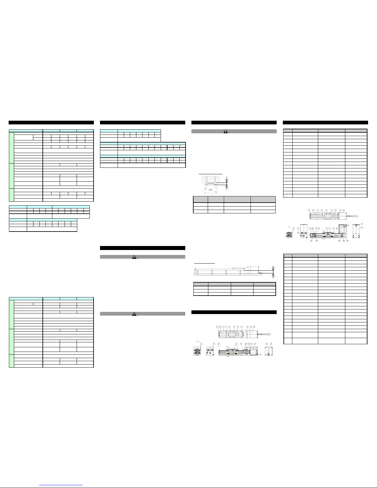
5 Names and Functions of Individual Parts
LEFS series – Ball screw drive
(See LEFS parts list in next column)
5 Names and Functions of Individual Parts (continued)
Parts list for LEFS
No. Part
Material
Remarks
1 Body Aluminium alloy Anodized
2 Rail guide -
3 Ball screw Ass’y -
4 Connector shaft Stainless steel
5 Table Aluminium alloy Anodized
6 Blanking plate Aluminium alloy Anodized
7 Seal band holder Synthetic resin
8 Housing A Aluminium die-cast Chromating
9 Housing B Alum inium alloy Anodized
10 Bearing holder Aluminium alloy
11 Motor mount Aluminium alloy Anodized
12 Coupling -
13 Motor cover Aluminium alloy Anodized
14 End cover Aluminium alloy Anodized
15 Motor -
16 Rubber bushing NBR
17 Band holder Stainless steel
18 Dust seal band Stainless steel
19 Bearing -
20 Bearing -
LEFB series – Belt drive
Parts list for LEFB
Work piece mounting
Actuator mounting
Model Bolt size
φA(mm) ℓ(mm)
LEF*16 M3 3.4 20
LEF*25 M4 4.3 24
LEF*32 M5 5.5 30
Model Bolt size
Maximum tightening
torque (N•m)
ℓ (Maximum thread
depth (mm])
LEF*16 M4 x 0.7 2.1 6
LEF*25 M5 x 0.8 5.7 8
LEF*32 M6 x 1 7.4 9
No. Part
Material
Remarks
1 Bod y Aluminium alloy Anodized
2 Rail guide -
3 Bel t -
4 Bel t holder A Carbon steel Chromating
5 Bel t holder B Aluminium alloy Anodized
6 Table Aluminium alloy Anodized
7 Bl anking plate Aluminium alloy Anodized
8 Seal band holder Synthetic resin
9 Housi ng A Aluminum die-cast Chromating
10 Pulley holder Aluminium alloy
11 Pulley shaft Stainless steel
12 End pulley Aluminium alloy Anodized
13 Motor pulley Aluminium alloy Anodized
14 Motor mount Aluminium alloy Anodized
15 Motor cover Aluminium alloy Anodized
16 End cover Aluminium alloy Anodized
17 Band holder Stainless steel
18 Motor -
19 Rubber bushing NBR
20 Stopper Aluminium alloy
21 Dust seal band Stainless steel
22 Bearing -
23 Bearing -
24
Tension
adjustment bolt
Chromium
molybdenum steel
Nickel plating
25
Pulley
holding bolt
Chromium
molybdenum steel
Nickel plating
Weight
Model
Stroke (mm)
Note1)
100 200 300 (400) 100 200 300 (400) 500 (600)
Weight (kg) 0.90 1.05 1.20 1. 35 1.84 2.12 2.40 2.68 2.96 3.24
Additional weight
for lock (kg)
Model
Stroke (mm)
Note1)
100 200 300 (400) 500 (600) (700) (800)
Weight (kg) 3.35 3.75 4.15 4. 55 4.95 5.35 5.75 6.15
Additional weight
for lock (kg)
LEFS16 LEFS25
0.12 0.19
LEFS32
0.35
Horizontal 9 10 20 20 40 45
Vertical 2 4 7.5 15 10 20
10 - 500 5 - 250 12 - 500 6 - 250 16 - 500 8 - 250
10 5 12 6 16 8
20 39 78 157 108 216
See the "Weight" table below for the applicable strokes.
123
0.15 (Screw mounting type), 0.17 (DIN rail mounting type)
51 57
LEFS 16 LEFS 25 LEFS 32
18 16 44
± 0.02
Ball screw
Linear guide
50 / 20
5 to 40 (No condensation or freezing)
35 to 85 (No condensation or freezing)
Electric specif ication
□28 □42 □56.4
Step motor (Servo 24VDC)
Incremental A/B phase (800 pulse/rotation)
24 ±10%
22 38 50
Lock
specification
No excitation operating type
3.6 5 5
24 ±10%
Holding force (N)
Power consumption (W)
Note8)
Rated voltage (VDC)
Stroke (mm)
Speed (mm/s)
Note2)
Work load (kg)
Note2)
Drive method
Guide type
Operating temperature range (℃)
Operating humidity range (%)
Motor size
Type of Motor
Model
Positioning repeatability (mm)
Lead (mm)
Impact resistance/vibration
resistance (m/s
2) Note3)
Actuator specificati on
Encoder
Rated voltage (VDC)
Power consumption (W)
Note4)
Standby power consumption when
operating (W)
Note5)
Momentary max. power
consumption (W)
Note6)
Controller weight (kg)
Type
Note7)
Work load (kg)
Note2)
Horizontal
See the "Weight" table below for the applicable strokes.
Incremental A/B phase (800 pulse/rotation)
24 ±10%
44
No excitation operating type
51 60
24 32 52
0.15 (Screw mounting type), 0.17 (DIN rail mounting type)
24 ±10%
4
3.6
19
5
36
48 - 1500
± 0.1
Lock
specification
Linear guide
Electric specific ation
□28
5
127
18 16
□42
□
56.4
48 48 48
5 to 40 (No condensation or freezing)
14
Step motor (Servo 24VDC)
1
48 - 1100548 - 1400
35 to 85 (No condensation or freezing)
BeltDrive method
Guide type
50 / 20
LEFB 32
Stroke (mm)
Model LEFB 16 LEFB 25
Actuator specification
Positioning repeatability (mm)
Lead equivalent (mm)
Impact resistance/vibration
resistance (m/s2)
Note3)
Speed (mm/s)
Note2)
Operating temperature range (℃)
Operating humidity range (%)
Motor size
Type of Motor
Encoder
Rated voltage (VDC)
Power consumption (W)
Note4)
Standby power consumption when
operating (W)
Note5)
Power consumption (W)
Note8)
Rated voltage (VDC)
Momentary max. power
consumption (W)
Note6)
Controller weight (kg)
Type
Note7)
Holding force (N)
Weight
Model
Stroke (mm)
Note1)
(300) 500 (600) (700) 800 (900) 1000
Weight (kg) 1.19 1.45 1.58 1.71 1.84 1.97 2.10
Additional weight
for lock (kg)
Model
Stroke (mm)
Note1)
(300) 500 (600) (700) 800 (900) 1000 (1200) (1500) (1800) (2000)
Weight (kg) 2.39 2.85 3.08 3.31 3.54 3.77 4.00 4.46 5.15 5.84 6.30
Additional weight
for lock (kg)
Model
Stroke (mm)
Note1)
(300) 500 (600) (700) 800 (900) 1000 (1200) (1500) (1800) (2000)
Weight (kg) 4.12 4.8 5.14 5.48 5.82 6.16 6.5 7. 18 8. 2 9.22 9.9
Additional weight
for lock (kg)
0.35
LEFB32
LEFB25
0.12
0.19
LEFB16
 Loading...