

Electric Actuator/Slider Type Ball Screw Drive Step Motor (See
RoHS
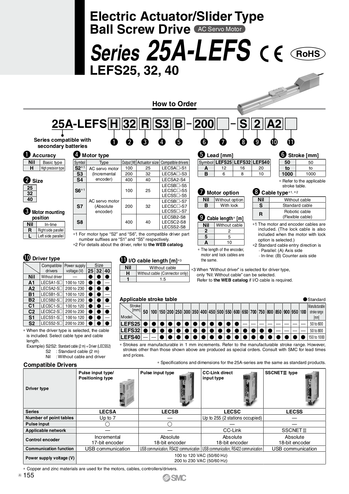
Series 25A-LEFS ( € GRUS LEFS16, 25, 32, 40
| How to Order | |||||||
|---|---|---|---|---|---|---|---|
|
25A-LEFSH2
Series compatible with secondary batteries |
200
6 |
9 1 | |||||
| Nil Basic type 16 | Applica | ble size | Compatible | ||||
|
H High precision type 25
32 |
Symbol | Туре | LEFS16 | LEFS25 | LEFS32 | LEFS40 |
controllers/
driver |
| 40 Motor mounting position Nil In-line B Biotht side parallel | Nil |
Step motor
(Servo/24 VDC) |
• | • | • | • |
LECP6
LECP1 LECPA LECPMJ |
| L Left side parallel | Α |
Servo motor
(24 VDC) |
_ | _ | LECA6 | ||
| Symbol LEFS16 LEFS25 LEFS32 LEFS40 A 10 12 16 20 B 5 6 8 10 |
CE-co
[CE-co 1 EMC LEC The I other certif |
aution
mpliant products] compliance was tes series. EMC depends on the r electrical equipment fied for SMC comp- ating conditions. As a |
sted by comb
configuration nt and wiring onents incor result it is ne |
ining the elect
of the custor . Therefore c porated into cessary for th |
tric actuator
ner's control p onformity to t the custome e customer fo |
LEF series ar
banel and the i the EMC director's equipmer o verify confort |
id the controller
relationship with ctive cannot be it under actual mity to the EMC |
| Stroke [mm] 50 50 to to 1000 1000 stroke table |
direc
②For t filter Refe |
tive for the machinery
he servo motor (24 v set (LEC-NFA). r to the WEB catale |
y and equipme
VDC) specific Og for the no |
ent as a whole
ation, EMC c ise filter set. |
e customer to
ompliance wa Refer to the |
as tested by ir
LECA Opera |
nstalling a noise |
noliant products
hen conformity to UI is rec UL1310 Class 2 power supply
olicable stroke table
| - | |||||||||||||||||||||
|---|---|---|---|---|---|---|---|---|---|---|---|---|---|---|---|---|---|---|---|---|---|
| Stroke | 50 | 100 | 150 | 200 | 250 | 300 | 350 | 100 | 450 | 500 | 550 | 600 | 650 | 700 | 750 | 800 | 850 | 900 | 950 | 1000 | Manufacturable |
| Model | 50 | 100 | 130 | 200 | 230 | 300 | 330 | 400 | 430 | 300 | 550 | 000 | 030 | 100 | 130 | 000 | 030 | 300 | 300 | 1000 | stroke range [mm] |
| LEFS16 | — | — | — | — | — | — | — | — | — | — | 50 to 500 | ||||||||||
| LEFS25 | ۲ | — | — | — | — | — | — | — | — | 50 to 600 | |||||||||||
| LEFS32 | — | — | — | — | 50 to 800 | ||||||||||||||||
| LEFS40 | _ | — | 150 to 1000 |
Strokes are manufacturable in 1 mm increments. Refer to the ma nufacturable stroke range. se shown above are produced as special orders. Consult with SMC for lead times and prices

SMC
Electric Actuator/Slider Type Ball Screw Drive Series 25A-LEFS
lal
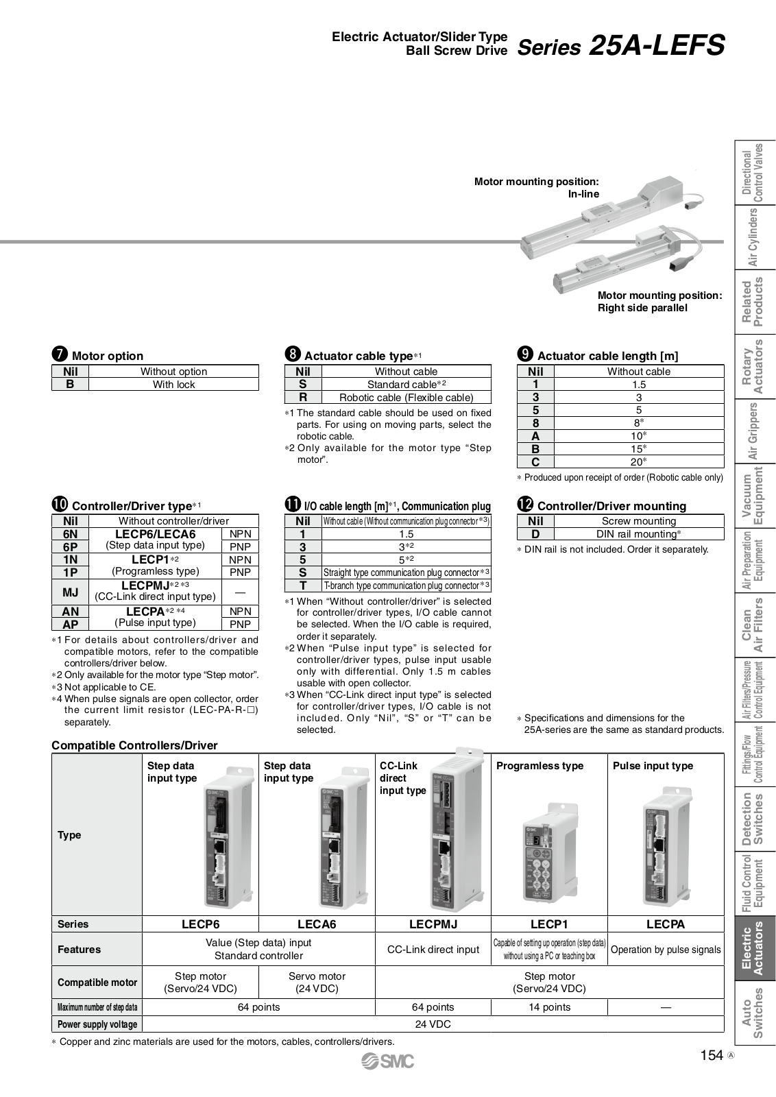
| Мо | tor mounting |
position:
In-line |
2.0 | 100110 | |||||
|---|---|---|---|---|---|---|---|---|---|
| M |
otor mounting position:
ight side parallel |
||||||||
| Motor optio | n | luator cat | le type*1 | tuator cat | ole lenath [m] | 1 | |||
| Nil | Without option | Nil | Without cable | Nil | Without cable | 44 | |||
| В | With lock | S | S | tandard cable*2 | 1 | 1.5 | C | ||
| R | Robotic | cable (Flexible cable) | 3 | 3 | |||||
|
*1 The s
parts. |
tandard cab
For using c |
le should be used on fixed
on moving parts, select the |
8 | 8* | |||||
| roboti | c cable. | ······································ | Ă | 10* | |||||
| *2 Only | available f | or the motor type "Step | B | 15* | |||||
| motor | • | * Produc | ed upon recei |
≥u
ot of order (Robotic cable onlv) |
( | ||||
| , | |||||||||
| Controller/D | Driver type*1 | W 1/0 a | able length | [m]*1, Communication plug | Co | ntroller/D | river mounting | 11.00 | |
| 10ut controller/drive |
Nil
1 |
Without cable (Wit | thout communication plug connector *3) | Nil | Screw mounting | ||||
| P (Step c | data input type) | PNP | 3 | 3*2 | * DIN ra | il is not inclu | ded. Order it separately | -41.00 | |
| N L | ECP1*2 | NPN | 5 | 5 5*2 | |||||
| 1P (Programless type) PNP | S Straight type communication plug connector *3 | 6 | |||||||
| IJ (CC-Link |
CPIVIJ*2 *3
direct input type) |
| _ | | *1 When "Without controller/driver" is selected | 4 | |||||
| ECPA*2 *4 | NPN | for co | for controller/driver types, I/O cable cannot | 1 | |||||
| AP (Puls | se input type) | PNP | be se | lected. When | n the I/O cable is required, | ||||
| For details abo | out controllers/dri | iver and | *2 Wher |
i separately
1 "Pulse in |
put type" is selected for | 0 | |||
| controllers/driver | r below. | Πρατισιο | contro | oller/driver | types, pulse input usable | l | 4 | ||
| Only available for | the motor type "Ste | p motor". | usable | e with open v | collector. | 1 | |||
| When pulse sign | als are open collect | tor, order | . *3 When | "CC-Link di | rect input type" is selected | 1 and | |||
| the current lim | it resistor (LEC-F | PA-R-□) | for co | ntroller/driv |
er types, I/O cable is not
"Nil" "S" or "T" can be |
ications and | dimensions for the | ||
| separately | inclu | * Snecit | ioutions und | 1 mil 17 V | |||||
| copulatory. | select | ed. |
* Specifi
25A-se |
eries are the | same as standard products. | AL. TH | |||
| mpatible Cor | ntrollers/Driver | select | ied. |
* Specifi
25A-se |
eries are the | same as standard products. | an/Elam | ||
| ompatible Cor |
ntrollers/Driver
Step data |
Step data | ted. | CC-Link |
* Specifi
25A-se |
eries are the | same as standard products. Pulse input type | Eliteration (Elise | |
| ompatible Cor |
ntrollers/Driver
Step data input type |
Step data | ted. |
CC-Link
direct input type |
* Specifi
25A-se Programles |
eries are the | same as standard products. Pulse input type | Etatione/Plan. | |
| empatible Cor |
ntrollers/Driver
Step data input type |
Step data |
CC-Link
direct input type |
* Specifi
25A-se |
eries are the | same as standard products. Pulse input type | Tational Theory | ||
| mpatible Cor |
ntrollers/Driver
Step data input type |
Step data |
CC-Link
direct input type |
* Specifi
25A-se |
eries are the | same as standard products. Pulse input type | |||
| ompatible Cor |
ntrollers/Driver
Step data input type |
Step data |
CC-Link
direct input type |
* Specifi
25A-se |
eries are the | same as standard products. | |||
| ompatible Cou |
ntrollers/Driver
Step data input type |
Step data
input type |
ied. |
CC-Link
direct input type |
* Specifi
25A-se |
eries are the | same as standard products. Pulse input type | ||
| ompatible Coi |
ntrollers/Driver
Step data input type |
Step data
input type |
red. |
CC-Link
direct input type |
* Specifi
25A-se |
eries are the | same as standard products. Pulse input type | ||
| ype |
ntrollers/Driver
Step data input type |
Step data
input type |
red. |
CC-Link
direct input type |
* Specifi
25A-se |
eries are the | same as standard products. Pulse input type | ||
| ompatible Coi |
Step data
input type |
Step data
input type |
red. |
CC-Link
direct input type |
* Specifi
25A-se |
eries are the | same as standard products. Pulse input type | ||
|
ompatible Cor
ype eries |
Step data
input type |
Step data
input type |
red. |
CC-Link
direct input type LECPMJ |
* Specifi
25A-se |
eries are the
as type |
same as standard products. Pulse input type | ||
|
ompatible Coi
ype eries eatures |
ntrollers/Driver Step data input type E |
ue (Step
itandard |
Step data
input type LEC. data) input controller |
red. |
CC-Link
direct input type LECPMJ CC-Link direct input |
* Specifi
25A-se Programles |
eries are the
as type P1 poperation (step data) c or teaching box |
same as standard products. Pulse input type | India Control Control Philipping |
|
pmpatible Cor
providence pries eatures pompatible motor |
Step data
input type |
ue (Step
itandard )r )C() |
Step data
input type LEC. data) input controller |
A6 |
CC-Link
direct input type LECPMJ CC-Link direct input |
* Specifi
25A-se Programles |
eries are the
as type Pl peration (step data) c or teaching box notor 4 VDC) |
same as standard products. Pulse input type | |
|
mpatible Coi
mpatible Coi rpe eries eatures ompatible motor |
Step data
input type Step data input type E LECP6 Values Step moto (Servo/24 VI |
ue (Step
itandard )r DC) 64 n |
Step data
input type LEC. data) input controller Servo r (24 VI oints |
A6 |
CC-Link
direct input type LECPMJ CC-Link direct input |
* Specifi
25A-se Programles EEC Capable of setting up of without using a PC Step n (Servo/2 14 pc |
eries are the
s type s type P P P P P P P P P P P P P |
same as standard products. Pulse input type United Statements LECPA Operation by pulse signals | |
|
pmpatible Coi
pries pries patures pmpatible motor imum number of step data wer supply voltage |
ntrollers/Driver Step data input type E |
ue (Step
standard r DC) 64 pr |
Step data
input type LEC. data) input controller Servo r (24 VI oints |
A6 |
CC-Link
direct input type LECPMJ CC-Link direct input |
* Specifi
25A-se Programles EEC Capable of setting up of without using a PC Step rn (Servo/2 14 pc |
eries are the
as type P1 operation (step data) c or teaching box notor 4 VDC) pints |
same as standard products. Pulse input type I | Arthe Fluid Candrel Control Hunter Hunter |

Incremental 17-bit encoder Absolute 18-bit encoder Absolute 18-bit encoder unication function supply voltage (V) USB communication USB communication, RS422 communication, RS422 communication, 100 to 120 VAC (50/60 Hz) 200 to 230 VAC (50/60 Hz)
SMC
* Copper and zinc materials are used for the motors, cables, controllers/drivers

⊘ SMC


Electric Actuator/Rod Type
n Motor (Servo/24 VDC) Servo Motor (24)
Series 25A-LEY ( E GRUS LEY16, 25, 32, 40 RoHS
How to Order 25A-LEY 16 100 C 1 6N 1 B secondary batteries Туре [CE-compliant products] DEMC compliance was tested by LECP6 Servo/24 VDC LECPA combining the electric actuator LEY series and the controller LEC Α LECA6 The FMC depends on the configu G Stroke [ ration of the customer's control panel and the relationship with other electrical equipment and wir-LEY25 ing. Therefore conformity to the EMC directive cannot be certified for SMC components incorporated fer to the ap into the customer's equipment under actual operating conditions ad and three As a result it is necessary for the customer to verify conformity to Male rod end the EMC directive for the machinery /1 rod end nut is incl When "With lock/motor cover" is selected for the top mounting and equipment as a whole and right/left side parallel types, the motor body will stick out o (2) For the servo motor (24 VDC) the end of the body for size 16 with strokes 30 or less. Check specification, EMC compliance for interference with workpieces before selecting a model. was tested by installing a noise ng Bracket Part No. for Series 25A filter set (LEC-NFA). Refer to the WEB catalog for the noise filter 25-I EV-I 0 set Refer to the LECA Operation Manual for installation. [UL-compliant products] 20-LET-L When conformity to UL is required RAYDENT® RAYDENT® the electric actuator and controller 70 16. EK driver should be used with a UL1310 Class 2 power supply. When ordering foot brackets, order 2 pieces per actuator *2 Parts belonging to each bracket are as follows Foot, Flange: Body mounting bolt, Double clevis: Clevis pin, Type C retaining ring for axis, Body mounting bolt Solid state auto switches should be ordered ser For details about auto switches, refer to page 164 D-M9N(V)-900 D-M9P(V)-900 D-M9B(V)-900 D-M9NW(V)-900, D-M9PW(V)-900, D-M9BW(V)-900 The actuator and controller/driver are sold as a package.
Confirm that the combination of the controller/driver and the actuator is correct
<Check the following before use.>
① Check the actuator label for model number (after "25A-"). This matches the c
2 Check Parallel I/O configuration matches (NPN or PNP)
* Refer to the operation manual for using the products. Please download it via our website. http://www.smcworld.com
SMC
Electric Actuator/Rod Type Series 25A-LEY

| V | ||||
|---|---|---|---|---|
| Symbol | Tuno | Motor mounting position | ||
| туре | Top/Parallel | In-line | ||
| Nil | Ends tapped (Standard)*2 | |||
| U | Body bottom tapped | |||
| L | Foot | — | ||
| F | Rod flange*2 | |||
| G | Head flange*2 | •4 | _ | |
| D | Double clevis*3 | _ | ||
| - | ||||
*1 Mounting bracket is shipped together. (but not assembled).
*2 For horizontal cantilever mounting with the rod flange, head flange and ends tapped. use the actuator within the following stroke range
- · I EY25: 200 or less
- E FY32/40: 100 or less
*3 For mounting with the double clevis, use the actuator within the following stroke range.
- · I FY16: 100 or less
- · LET 16. 100 of less
- *4 Head flange is not available for the + Head IIa I FY32/40
| ₿ co | ntroller/Driver mounting |
|---|---|
| Nil | Screw mounting |
| D | DIN rail mounting*1 |
*1 DIN rail is not included. Order it se
| • | |
|---|---|
| Nil | Without cable |
| S | Standard cable*2 |
| S | Standard cable *2 | ||||
|---|---|---|---|---|---|
| R | Robotic cable (Flexible cable) | ||||
*1 The standard cable should be used on fixed parts. For using on moving parts, select the robotic cable.
*2 Only available for the motor type "Step motor".
| i D | Controllor/Driver | tvpo*1 |
|---|
| ntroller/Driver type** | ||||||
|---|---|---|---|---|---|---|
| Nil | Without controller/driver | |||||
| 6N | LECP6/LECA6 | NPN | ||||
| 6P | (Step data input type) | PNP | ||||
| 1N | LECP1*2 | NPN | ||||
| 1P | (Programless type) | PNP | ||||
| MJ |
LECPMJ*2*3
(CC-Link direct input type) |
_ | ||||
| AN | LECPA*2 *4 | NPN | ||||
| AP | (Pulse input type) | PNP | ||||
*1 For details about controllers/driver and compatible motors refer to the compatible controllers/driver below
- *2 Only available for the motor type "Step motor"
-
*3 Not applicable to CE
- *4 When pulse signals are open collector. order the current limit resistor (LEC-PA-Bseparately
* Specifications and dimensions for the 25A-series are the same as standard products
| Compatible Con | trollers/Driver | ||||
|---|---|---|---|---|---|
| Туре |
Step data
input type |
Step data
input type |
CC-Link
direct input type |
Programless type | Pulse input type |
| Series | LECP6 | LECA6 | LECPMJ | LECP1 | LECPA |
| Features |
Value (Step
Standard |
data) input
controller |
CC-Link direct input |
Capable of setting up operation
(step data) without using a PC or teaching box |
Operation by
pulse signals |
| Compatible motor |
or Step motor Servo motor
(Servo/24 VDC) (24 VDC) |
Step motor
(Servo/24 VDC) |
|||
| Maximum number of step data | 64 p | oints | 64 points | 14 points | _ |
| Power supply voltage | 24 VDC | ||||
SMC
* Copper and zinc materials are used for the motors, cables, contro
D Actuator cable length [m]
| Nil | Without cable |
|---|---|
| 1 | 1.5 |
| 3 | 3 |
| 5 | 5 |
| 8 | 8* |
| Α | 10* |
| В | 15* |
| С | 20* |
* Produced upon receipt of order (Robotic cable only)
| I/O cable length [m]*1, Communication plug | ||||||
|---|---|---|---|---|---|---|
| Nil | Without cable (Without communication plug connector*3) | |||||
| 1 | 1.5 | |||||
| 3 | 3*2 | |||||
| 5 | 5 *2 | |||||
| S | Straight type communication plug connector*3 | |||||
| Т | T-branch type communication plug connector*3 | |||||
| *1 Whe | n "Without controller/driver" is selected | |||||
- be selected. Refer to the catalog CAT, F102 if I/O cable is required.
- *2 When "Pulse input type" is selected for controller/driver types, pulse input usable only with differential. Only 1.5 m cables usable with open collector
- *3 When "CC-I ink direct input type" is selected for controller/driver types. I/O cable is not included. Only "Nil", "S" or "T" can be
Electric Actuator/Rod Type
AC Servo Motor
Series 25A-LEY ( E ROHS) LEY25, 32 Size 25, 32
How to Order

| Nil | Basic type | ||||
|---|---|---|---|---|---|
| Н | High precision type | ||||

| 5 Lead [mm] | ||||||||
|---|---|---|---|---|---|---|---|---|
| Symbol | LEY25 | LEY32* | ||||||
| Α | 12 | 16 (20) | ||||||
| В | 6 | 8 (10) | ||||||
| С | 3 | 4 (5) | ||||||
* The values shown in ( ) are the lead for size 32 ton mounting right/left side parallel types (Equivalent lead which includes the nulley ratio [1 25:1]
| 30 | 30 |
|---|---|
| to | to |
| 500 | 500 |
* Refer to the table below for details
Rod end thread
| Nil | Female rod end |
|---|---|
| м |
Male rod end
(1 rod end nut is included.) |
cket Part No. for Series 25A
| Nil | Without option | |
|---|---|---|
| В | With lock* | |
When "With lock" is selected for left side parallel types, the mot end of the body for size 25 with for interference with workpi

| Symbol | Turne | Motor mounting position | |||
|---|---|---|---|---|---|
| Symbol | туре | Top/Parallel | In-line | ||
| Nil | Ends tapped (Standard)*2 | ٠ | |||
| U | Body bottom tapped | ۲ | |||
| L | Foot | _ | |||
| F | Rod flange*2 | •*4 | ٠ | ||
| G | Head flange*2 | •*5 | |||
| D | Double clevis*3 | _ | |||
*1 Mounting bracket is shipped together. (but not assembled).
- *2 For horizontal cantilever mounting with the rod flange, head flange and ends tapped, use the actuator within the following stroke range. · LEY25: 200 or less · LEY32: 100 or less
- *3 For mounting with the double clevis, use the actuator within the following stroke range. · LEY25: 200 or less · LEY32: 200 or less
- *4 Rod flange is not available for the LEY25 with stroke 30 and motor option "With lock"
- *5 Head flance is not available for the LEY32
When ordering foot brackets, order 2 pieces per ac *2 Parts belonging to each bracket are as follows.
Foot, Flange: Body mounting bolt, Double clevis: Clevis pin, Type C retaining ring for axis. Body mounting bolt
BAYDENT®
| Standa | Stanuaru | |||||||||||
|---|---|---|---|---|---|---|---|---|---|---|---|---|
| Stroke | 20 | 50 | 100 | 150 | 200 | 250 | 200 | 250 | 100 | 150 | 500 | Manufacturable |
| Model | 30 | 50 | 100 | 150 | 200 | 250 | 300 | 350 | 400 | 450 | 500 | stroke range [mm] |
| LEY25 | — | — | 15 to 400 | |||||||||
| LEY32 | 20 to 500 | |||||||||||
* Consult with SMC for non-standard strokes as they are produced as special orders
A 150
| 500 | stroke range [mm] | So |
|---|---|---|
| — | 15 to 400 | |
| 20 to 500 | D-N |
SMC
or details about auto switches, refer to page 164
plicable auto switches
M9N(V)-900, D-M9P(V)-900, D-M9B(V)-900 D-M9NW(V)-900, D-M9PW(V)-900, D-M9BW(V)-900
| the top mounting and right/ | Nil |
|---|---|
| or body will stick out of the | U |
| strokes 30 or less. Check |
| n | |
| Without option | 9 |
| Symbol | Туре | Output [W] | Actuator size | Compatible drivers*2 | ||||||
| S2 |
AC servo motor
(Incremental encoder) |
100 | 25 | LECSA⊡-S1 | ||||||
| S3 |
AC servo motor
(Incremental encoder) |
200 | 32 | LECSA□-S3 | ||||||
| S6 |
AC servo motor
(Absolute encoder) |
100 | 25 |
LECSB□-S5
LECSC□-S5 LECSS□-S5 |
||||||
| S7 |
AC servo motor
(Absolute encoder) |
200 | 32 |
LECSB□-S7
LECSC□-S7 LECSS□-S7 |
||||||
*1 For motor type "S2" and "S6", the compatible driver part number suffixes are "S1" and "S
*2 For details about the driver, refer to the WEB catalog
Electric Actuator/Rod Type Series 25A-LEY
Size 25, 32


op/Parallel
Motor mounting po
Cable type*
| Nil | Without cable |
|---|---|
| S | Standard cable |
| R | Robotic cable (Flexible cable) |
* The motor and encoder cables are included. (The lock cable is also included when the motor with lock option is selected.) * Standard cable entry direction is
Standard cable entry direction i Top/Parallel: (A) Axis side
In-line: (B) Counter axis side
I/O cable length [m]*
| Nil | Without cable | ||
|---|---|---|---|
| Н | Without cable (Connector only) | ||
| 1 | 1.5 | ||
| * When "Without driver" is selected for driver | |||
* When "Without driver" is selected for driver type, only "Nil: Without cable" can be selected. Refer to the WEB catalog if I/O cable is required.
Cable length* [m]
| Nil | Without cable |
|---|---|
| 2 | 2 |
| 5 | 5 |
| Α | 10 |
* The length of the encoder, motor and lock cables are the same.
| Compatible drivers | Power supply voltage (V) | |
|---|---|---|
| Nil | Without driver | — |
| A1 | LECSA1-S□ | 100 to 120 |
| A2 | LECSA2-S□ | 200 to 230 |
| B1 | LECSB1-S□ | 100 to 120 |
| B2 | LECSB2-S□ | 200 to 230 |
| C1 | LECSC1-S□ | 100 to 120 |
| C2 | LECSC2-S□ | 200 to 230 |
| S1 | LECSS1-S | 100 to 120 |
| S2 | LECSS2-S□ | 200 to 230 |
When the driver type is selected, the cable is included. Select cable type and cable length. Example)
S2S2: Standard cable (2 m) + Driver (LECSS2)
S2S2: Standard cable (2 m) + Drive S2 : Standard cable (2 m)
Nil : Without cable and driver
* Specifications and dimensions for the 25A-series are the same as standard products.
| Driver type |
Pulse input type/
Positioning type |
Pulse input type |
CC-Link direct
input type |
SSCNET II type |
|---|---|---|---|---|
| Series | LECSA | LECSB | LECSC | LECSS |
| Number of point tables | Up to 7 | — | Up to 255 (2 stations occupied) | — |
| Pulse input | 0 | 0 | _ | — |
| Applicable network | — | _ | CC-Link | SSCNETI |
| Control encoder |
Incremental
17-bit encoder |
Absolute
18-bit encoder |
Absolute
18-bit encoder |
Absolute
18-bit encoder |
| Communication function | USB communication | USB communication, RS422 communication | USB communication, RS422 communication | USB communication |
| Power supply voltage (V) |
100 to 120 VAC (50/60 Hz)
200 to 230 VAC (50/60 Hz) |
|||
* Copper and zinc materials are used for the motors, cables, controllers/drivers


 Loading...