

SMC Networks LECSC Series Operation Manual
LEC-OM06008
(Doc no. JXC※-OMT0056-A)
PRODUCT NAME
AC Servo Motor Driver
(CC-Link Type)
MODEL / Series / Product Number
LECSC Series
(Simplified edition)

文書管理 No. - 旧文書体系 No. 対応表
文書管理 No.
旧文書体系 No.
JXC※-OMT0056
LEC-OM06007
JXC※-OMT0056-A
LEC-OM06008
本書は、対応文書の原紙と一緒に保管する。

-1-
CONTENTS
CONTENTS .................................................................................................... 1
Introduction ................................................................................................... 7
1. Configuration ............................................................................................ 8
2. Pre-Operation Procedure .......................................................................... 9
2.1 Flow chart ................................................................................................................... 9
2.2 Driver display ........................................................................................................... 10
3. Wiring ......................................................................................................... 12
3.1 Power Supply Wiring ............................................................................................... 12
3.2 I/O signal connection .............................................................................................. 13
3.2.1 Connection example (Sink I/O interfaces) ............................................................................ 13
3.2.2 Source I/O interfaces .............................................................................................................. 14
3.3 Wiring of PLC and driver ......................................................................................... 15
4. Parameter list (Driver side) ....................................................................... 17
5. Parameter Configuration using Setup software (MR Configurator2TM) . 18
5.1Setup software (MR Configurator2TM) ..................................................................... 18
5.1.1 Installation Method .................................................................................................................. 18
5.2 Basic driver set-up for Initial Test Drive ................................................................ 18
5.2.1 Start up the Setup software (MR Configurator2TM) .............................................................. 19
5.2.2 “System Settings” ................................................................................................................... 20
5.2.3 Model Selection ....................................................................................................................... 20
5.2.4 Driver ON LINE Check ............................................................................................................ 21
5.2.5 Help Function .......................................................................................................................... 21
5.3 Parameter Settings (Driver side) ............................................................................ 22
5.3.1 Change of parameter block .................................................................................................... 23
5.3.2 Change of parameter block .................................................................................................... 23
5.3.3 Parameter Configuration Method (Ex. “Control mode” Selection) .................................... 24
5.3.4 Recommended Parameter Values by Actuator Model......................................................... 25
5.3.5 Absolute position detection system ..................................................................................... 30
5.3.6 Remote register-based position/speed specifying system selection ................................. 31
5.3.7 Electronic Gears ...................................................................................................................... 32
5.3.8 Verify of parameters ................................................................................................................ 33
5.3.9 Parameter initialization ........................................................................................................... 34
5.4 JOG Mode in the Setup Software ........................................................................... 35
5.4.1 JOG Mode................................................................................................................................. 36
5.5 Changing I/O Signal Allocation .............................................................................. 37
5.5.1 Automatic Input Signal ON Selection Parameter Configuration ........................................ 37
5.5.2 Initial I/O Signal Allocation ..................................................................................................... 40
5.5.3 Signal Allocation using Setup Software ............................................................................... 40
5.5.4 Allocation Examples ............................................................................................................... 41
5.5.5 I/O Signal Allocation Check.................................................................................................... 43
5.5.6 Parameter setting when using it by I/O signal (CN6 connector use) ................................ 44
5.6 Positioning Mode in Setup Software ...................................................................... 46
5.6.1 Positioning Mode .................................................................................................................... 47
5.6.2 Motor speed Configuration .................................................................................................... 48
5.6.3 Acceleration/deceleration Time Configuation ...................................................................... 49

-2-
5.6.4 Move distance Configuration and Operation ....................................................................... 50
5.7 Positioning (Point Table) Operation using the Setup Software ........................... 51
5.7.1 Point table List ......................................................................................................................... 51
5.7.2 Point table Data ....................................................................................................................... 52
5.7.3 Point table (Target position) Configuration .......................................................................... 53
5.7.4 Point table (Servo Motor Speed) Configuration ................................................................... 56
5.7.5 Point Table (Acceleration time constant/Deceleration time constant) Configuration ..... 57
5.7.6 Other Settings .......................................................................................................................... 57
5.7.7 Single-Step Feed ..................................................................................................................... 58
5.8 Saving/Loading Parameters ................................................................................... 59
5.8.1 Saving Parameters .................................................................................................................. 59
5.8.2 To Load saved Parameters ..................................................................................................... 60
5.9 Saving/Loading Project ........................................................................................... 61
5.9.1 Saving Project ......................................................................................................................... 61
5.9.2 To Load saved Project ............................................................................................................ 62
5.10 Saving/Loading Point table ................................................................................... 63
5.10.1 Saving Point table ................................................................................................................. 63
5.10.2 To Load saved Point table .................................................................................................... 64
5.11 Acquisition of motion waveform with graph monitor ......................................... 65
5.11.1 Under the setting Tab: Setting of the items to display the graph .................................... 66
5.11.2 Trigger wait ............................................................................................................................ 70
5.11.3 Operation Instruction ............................................................................................................ 71
5.11.4 Saving of waveform .............................................................................................................. 72
5.12 Display All Monitor List ........................................................................................ 73
6. CC-Link setting ......................................................................................... 75
6.1 Station number setting ............................................................................................ 76
6.2 Communication baud rate setting .......................................................................... 77
6.3 Occupied station count setting .............................................................................. 77
6.4 Parameter setting by PLC ....................................................................................... 78
6.5 Device ....................................................................................................................... 79
6.5.1 Detailed explanation of Input signals (Input devices) ......................................................... 82
6.5.2 Detailed explanation of Output signals (Output devices) ................................................... 87
6.5.3 Detailed explanation of Remote registers input .................................................................. 89
6.5.4 Detailed explanation of Remote registers output ................................................................ 91
6.6 Monitor1 (RWwn) ・ Monitor2 (RWwn+1) ............................................................... 92
6.6.1 Timing chart of monitor .......................................................................................................... 93
6.6.2 Pxrogramming example of the monitor ................................................................................ 94
6.7 Read instruction code No. (0000h to 0AFFh) ........................................................ 95
6.7.1 Timing chart of read instruction code ................................................................................ 100
6.7.2 Programming examples of read instruction code ............................................................. 100
6.8 Write instruction code No. (8010h to 91FFh) ....................................................... 101
6.8.1 Timing chart of write instruction code ................................................................................ 104
6.8.2 Programming examples of write instruction code ............................................................ 104
6.9 Respond codes (RWrn+2) ..................................................................................... 105
7. Home position return ................................................................................ 106
7.1 Setting of home position return ........................................................................... 106
7.1.1 Home position return ............................................................................................................ 107
7.1.2 Stopper type home position return. .................................................................................... 108
8. Positioning operation method of operation ............................................ 110

-3-
8.1 Point table method ................................................................................................ 112
8.1.1 Positioning operation indication of the point table method (Example) ........................... 112
8.2 Remote register method ....................................................................................... 116
8.2.1 Positioning operation indication of the remote register method (Example) ................... 116
9. Troubleshooting ........................................................................................ 121
9.1 Alarms and Warning List ....................................................................................... 121
9.2 Alarm Display ......................................................................................................... 122
-4-
LECSC Series / Driver
Safety Instructions
These safety instructions are intended to prevent hazardous situations and/or equipment damage.
These instructions indicate the level of potential hazard with the labels of “Caution,” “Warning” or “Danger.”
They are all important notes for safety and must be followed in addition to International Standards (ISO/IEC),
Japan Industrial Standards (JIS)*1) and other safety regulations*2).
*1) ISO 4414: Pneumatic fluid power -- General rules relating to systems
ISO 4413: Hydraulic fluid power -- General rules relating to systems
IEC 60204-1: Safety of machinery -- Electrical equipment of machines (Part 1: General requirements)
ISO 10218-1992: Manipulating industrial robots -- Safety
JIS B 8370: General rules for pneumatic equipment.
JIS B 8361: General rules for hydraulic equipment.
JIS B 9960-1: Safety of machinery – Electrical equipment for machines. (Part 1: General requirements)
JIS B 8433-1993: Manipulating industrial robots - Safety.etc.
*2) Labor Safety and Sanitation Law, etc.
Caution
Caution indicates a hazard with a low level of risk which, if not avoided, could result in minor or
moderate injury.
Warning
Warning indicates a hazard with a medium level of risk which, if not avoided, could result in death
or serious injury.
Danger
Danger indicates a hazard with a high level of risk which, if not avoided, will result in death or
serious injury.
Warning
1. The compatibility of the product is the responsibility of the person who designs the equipment or
decides its specifications.
Since the product specified here is used under various operating conditions, its compatibility with specific
equipment must be decided by the person who designs the equipment or decides its specifications based
on necessary analysis and test results.
The expected performance and safety assurance of the equipment will be the responsibility of the person
who has determined its compatibility with the product.
This person should also continuously review all specifications of the product referring to its latest catalog
information, with a view to giving due consideration to any possibility of equipment failure when
configuring the equipment.
2. Only personnel with appropriate training should operate machinery and equipment.
The product specified here may become unsafe if handled incorrectly.
The assembly, operation and maintenance of machines or equipment including our products must be
performed by an operator who is appropriately trained and experienced.
3. Do not service or attempt to remove product and machinery/equipment until safety is confirmed.
The inspection and maintenance of machinery/equipment should only be performed after measures to
prevent falling or runaway of the driven objects have been confirmed.
When the product is to be removed, confirm that the safety measures as mentioned above are
implemented and the power from any appropriate source is cut, and read and understand the specific
product precautions of all relevant products carefully.
Before machinery/equipment is restarted, take measures to prevent unexpected operation and
malfunction.
4. Contact SMC beforehand and take special consideration of safety measures if the product is to
be used in any of the following conditions.
1) Conditions and environments outside of the given specifications, or use outdoors or in a place exposed
to direct sunlight.
2) Installation on equipment in conjunction with atomic energy, railways, air navigation, space, shipping,
vehicles, military, medical treatment, combustion and recreation, or equipment in contact with food and
beverages, emergency stop circuits, clutch and lock circuits in press applications, safety equipment or
other applications unsuitable for the standard specifications described in the product catalog.
3) An application which could have negative effects on people, property, or animals requiring special

-5-
safety analysis.
4) Use in an interlock circuit, which requires the provision of double interlock for possible failure by using
a mechanical protective function, and periodical checks to confirm proper operation.
Note that the CAUTION level may lead to a serious consequence according to conditions. Please follow the
instructions of both levels because they are important to personnel safety.
-6-
LECSC Series / Driver
Safety Instructions
Caution
The product is provided for use in manufacturing industries.
The product herein described is basically provided for peaceful use in manufacturing industries.
If considering using the product in other industries, consult SMC beforehand and exchange specifications
or a contract if necessary.
If anything is unclear, contact your nearest sales branch.
Limited warranty and Disclaimer/Compliance Requirements
The product used is subject to the following “Limited warranty and Disclaimer” and “Compliance
Requirements”.
Read and accept them before using the product.
Limited warranty and Disclaimer
The warranty period of the product is 1 year in service or 1.5 years after the product is delivered,
whichever is first.
*3)
Also, the product may have specified durability, running distance or replacement parts. Please
consult your nearest sales branch.
For any failure or damage reported within the warranty period which is clearly our responsibility, a
replacement product or necessary parts will be provided.
This limited warranty applies only to our product independently, and not to any other damage
incurred due to the failure of the product.
Prior to using SMC products, please read and understand the warranty terms and disclaimers noted
in the specified catalog for the particular products.
*3) Vacuum pads are excluded from this 1 year warranty.
A vacuum pad is a consumable part, so it is warranted for a year after it is delivered.
Also, even within the warranty period, the wear of a product due to the use of the vacuum pad or failure due
to the deterioration of rubber material are not covered by the limited warranty.
Compliance Requirements
When the product is exported, strictly follow the laws required by the Ministry of Economy, Trade and
Industry (Foreign Exchange and Foreign Trade Control Law).

-7-
Introduction
It is recommended that the operator read the operation manual for LECSC prior to use.
For the handling and details of other equipment, please refer to the operation manual for used equipment.
Check that the main circuit power supply (AC100V/AC200V) and controller circuit power supply
(AC100V/AC200V) are wired correctly.
When using the emergency stop SW etc. provided by customer, wire it to the EMG (Forced stop) of the
input/output signal(CN6-1).
When wiring, I/O connector(LE-CSNA) or I/O cable(LEC-CSNA-1) is required.
(EMG (Forced stop) cannot be controlled with CC-Link.)
Please put the wiring for EMG (Forced stop) into the state of EMG release (operational).
(EMG (Forced stop) can be compulsorily set to automatic ON by the parameter.)
Please refer to chapter 4 of the “LECSC Operation Manual” and chapter 3 of the “LECSC Operation Manual
(Simplified Edition)” for details.
When setup software (MR Configurator2TM) is used, the LECSC□-□ model selection is required.
Select 'MR-J3-T' through “Model" - "New" and "Project".
-8-
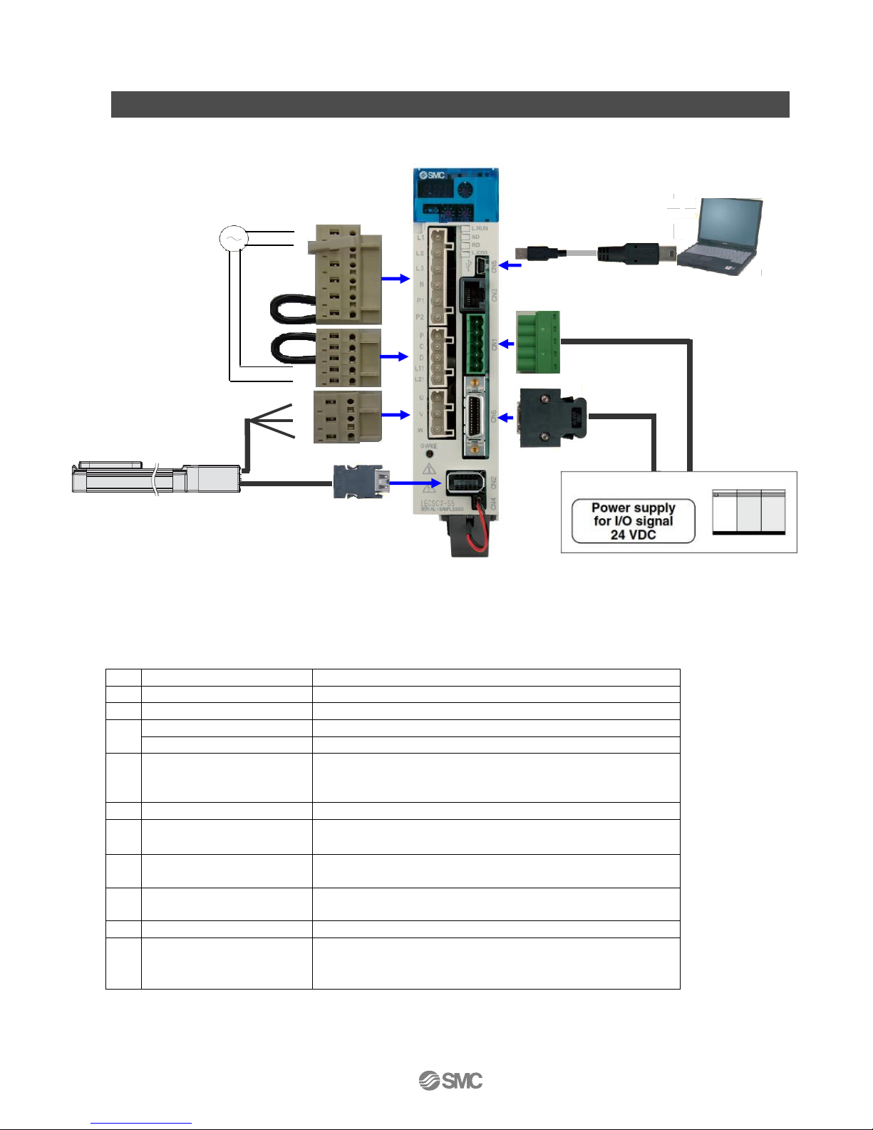
1. Configuration
Minimum equipment and wiring requirements to get started
(*1) Refer to “LECSC Operation Manual”, Chapter 4 for further details if the power supply voltage is
100VAC.
(*2) When wiring to EMG (Forced stop) of input/output signal(CN6-1), I/O connector(LE-CSNA) or I/O
cable(LEC-CSNA-1) is required.
(EMG (Forced stop) cannot be controlled with CC-Link.)
1
Driver
LECSC*-S*
2
Motor cable
LE-CSM-***
3
Encoder cable
LE-CSE-***
4
I/O connector
LE-CSNA
I/O cable
LEC-CSNA-1
5
CC-Link connector
CN1 (Accessory)
of Mitsubishi Electric System & Service Co., Ltd.
Product number : K05A 502 306 00
6
USB cable
LEC-MR-J3USB
7
Setup software
(MR Configurator2TM)
LEC-MRC2E
8
Main circuit power
supply connector
CNP1 (Accessory)
9
Control circuit power
supply connector
CNP2 (Accessory)
10
Motor connector
CNP3 (Accessory)
11
Battery
LEC-MR-J3BAT(a bundled item)
It is unnecessary when using it with the incremental
system.
Note) The lock cable option is not shown on this drawing. Refer to the “LECSC Operation Manual” for
details.
Ex) 200 V AC (*1)
3
2
Electric Actuators
Ex) LEF
L1
L2
L3 N P1
P2 P C
D
L11
L21 U V
W
4 (*2)
PC
6 7 8 9 10
11
5
Provided
by customer
Provided
by customer
1
Provided
by customer
PLC (CC-Link master unit)
-9-
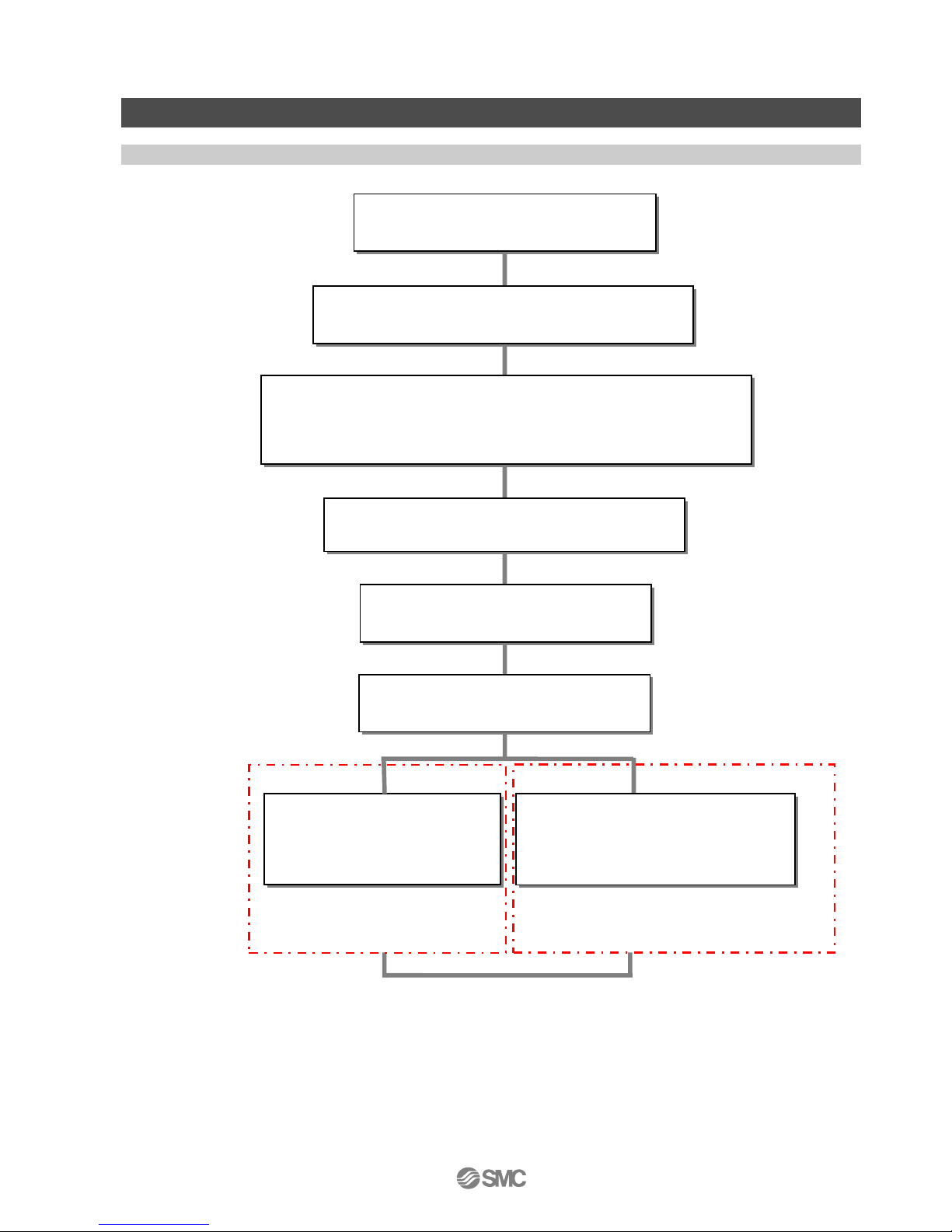
2. Pre-Operation Procedure
2.1 Flow chart
Wiring
See [3. Wiring]
Parameter setting
See [4. Parameter list (Driver side)]
[Point table method]
setting
See [8.1. Point table method]
- Remote register control by writing
the position and the speed data to
the remote register
- Point table control by writing
the point table data to the
driver
[Remote register method]
setting
See [8.2. Remote register method]
CC-Link setting
See [6. CC-Link setting]
Home position return
See [7. Home position return]
Signal allocation setting
See [5.5 Changing I/O Signal Allocation]
Parameter Settings using the Setup Software (MR
Configurator2TM)
see [5. Parameter Settings using the Setup Software (MR
Configurator2TM)]
Occupies only 2 stations.
-10-
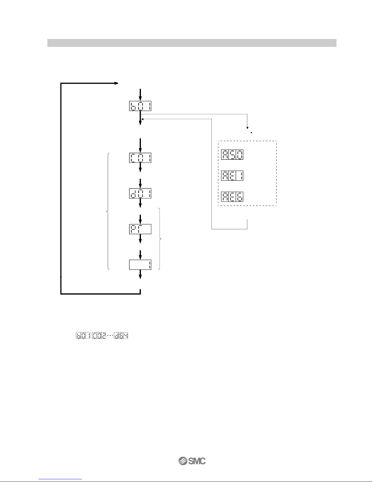
2.2 Driver display
On the driver display (three-digit, seven-segment display), check the status of communication with the CC-Link driver
at power-on, check the station number, and diagnose a fault at occurrence of an alarm.
(1) Display sequence
During forced stop
At occurrence of overload
warning (Note 2)
At occurrence of overload
Servo amplifier power ON
CC-Link master module power ON
CC-Link communication beginning
Servo ON
Not ready
(Note 3)
Ready
(Note 3)
(Note 3)
Flicker
display
Alarm reset or
warning
(Note 1)
When alarm warning
No. is displayed
Flicker
display
Flicker
display
When alarm occurs,
alarm code appears.
Servo amplifier power OFF
Waiting for CC-Link communication
Point table No. display
2s later
2s later
Note 1. Only alarm and warning No. are displayed, but no station No. is displayed.
2. If warning other than AE6 occurs during the servo on, flickering the second place of decimal point indicates that it is during the
servo on.
3. The right-hand segments of b01, c02 and d16 indicate the axis number.
(Below example indicates Station No.1)
Station
No.1
Station
No.2
Station
No.64
Driver power ON
Driver power OFF
-11-
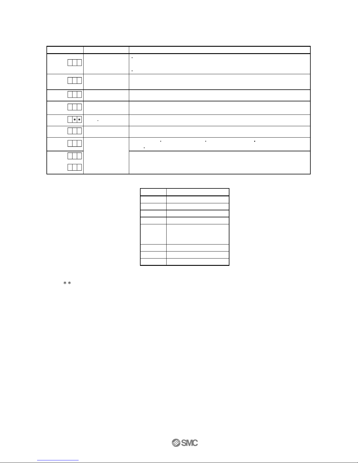
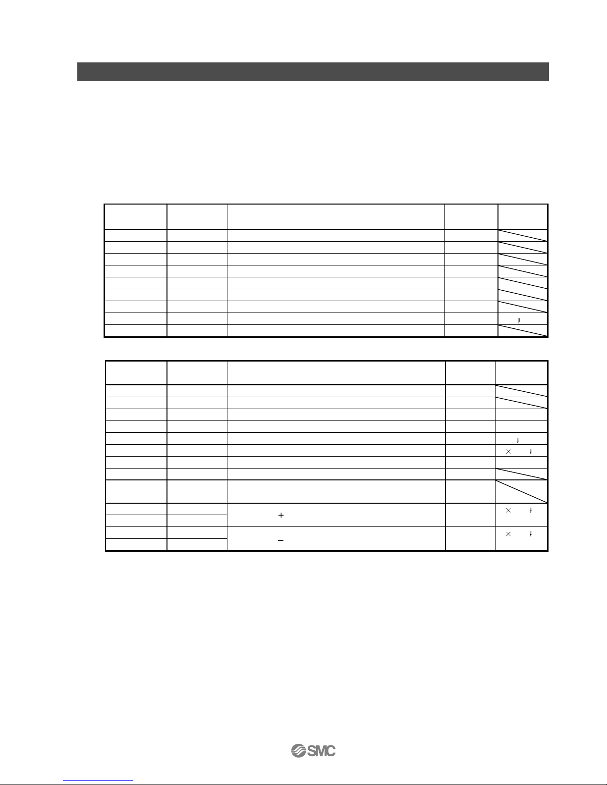
(2) Indication list
Indication
Status
Description
b # #
Waiting for CC-Link
communication
Power of the CC-Link master module was switched on at the condition that the power of
CC-Link master module is OFF.
The CC-Link master module is faulty.
(Note 1)
d # #
Ready
The servo was switched on after completion of initialization and the driver is ready to operate.
(This is indicated for 2 seconds.)
(Note 1)
C # #
Not ready
The driver is being initialized or an alarm has occurred.
(Note 2)
$ $ $
Ready for operation
Two seconds have passed after the driver is ready to operate by turning ON the servo-on
(RYn1).
(Note 3)
A
Alarm Warning
The alarm No./warning No. that occurred is displayed. (Refer to section 10.4.)
8 88
CPU error
CPU watchdog error has occurred.
(Note 4)
0 0.b
(Note 4)
Test operation mode
JOG operation positioning operation programmed operation DO forced
output single-step feed
(Note 1)
# #.d
Motor-less operation
# #.C
Note 1. ## denotes any of numerals 00 to 16 and what it means is listed below.
##
Description
00
Set to the test operation mode.
01
Station number 1
02
Station number 2
03
Station number 3
:
:
:
:
62
Station number 62
63
Station number 63
64
Station number 64
Note 2. $$$ indicates numbers from 0 to 255, and the number indicates the executing point table number.
3. indicates the warning/alarm No.
4. Requires set up software(MR Configurator2TM) .
-12-
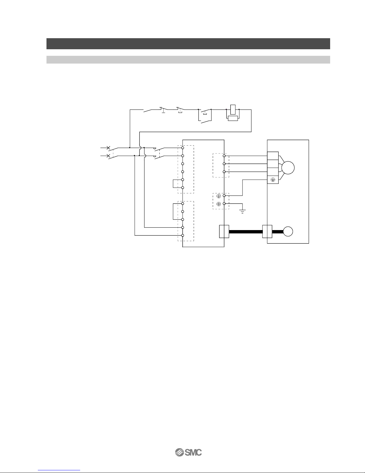
3. Wiring
3.1 Power Supply Wiring
Connect the actuator and driver power supply.
(1) LECSC (Absolute encoder)
EX.) Power supply is AC200V single phase
P
N
Trouble
L
1
L2
L3
1-phase
200 to
230VAC
P
1
P
2
L11
L
21
D
C
U
V
W
(Note 1)
(Note 2)
CNP1
CNP3
PE
CNP2
U
V
W
M
Motor
Encoder
CN2
(Note 3)
Encoder cable
(Note 5)
MCNFB
Servo motorServo amplifier
RA
Emergency stop
OFF
MC
ON
MC
SK
(Note 6)
(Note 7)
[1] Power supply input terminal: Supply specified power supply.
[2] - Connect the motor power supply input terminal (U, V, W) to the driver power terminal (U, V, W)
- Connect the motor ground terminal to the driver ground terminal.
- Connect the cable for detector.
[3] Supply specified power to the control circuit power supply.
Refer to “LECSC Operation Manual”, Chapter 4 for further details if the power supply voltage is 100VAC.
Driver
[1]
[3]
[2]
-13-
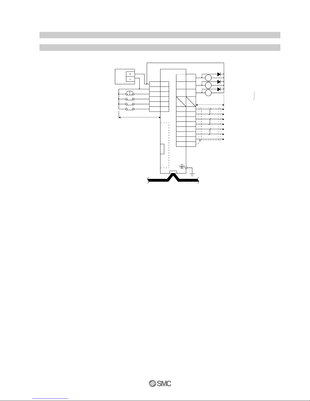
3.2 I/O signal connection
3.2.1 Connection example (Sink I/O interfaces)
An example of a connection for the I/O signal connection is shown below. Connect wires as necessary.
SD
LBR
LAR
LA
LB
LZ
LZR
LG
15
12
25
RA1
RA2
RA3
14 RD
ALM
16 ZP
CN6
11
24
13
26
1
2
3
Plate
4
5
17
EMG
DOG
LSP
LSN
DICOM
DOCOM
23
+
MR-J3USBCBL3M
(Option)
CN5
(Note 7)
MR Configurator
Personal
computer
CN1
CC-Link
Encoder A-phase pulse
(differential line driver)
Encoder B-phase pulse
(differential line driver)
Control common
Encoder Z-phase pulse
(differential line driver)
24VDC
power
supply
(Note 4)
(Note 8)
Proximity dog
Forward rotation stroke end
Reverse rotation stroke end
(Note 3, 5)
(Note 9)
(Note 5)
Forced stop
(Note 9)
Ready
Trouble (Note 6)
Home position
return completion
(Note 2)
10m or less
Servo amplifier
CN6
10m or less
(Note 1)
Refer to“LECSC Operation Manual”,section 4.2 for wiring details.
Refer to “LECSC Operation Manual”,section 4.5 for input/output signal details.
Driver
LEC-MR-J3US
(Note 7)
Set up software
(MR Configurator)
-14-
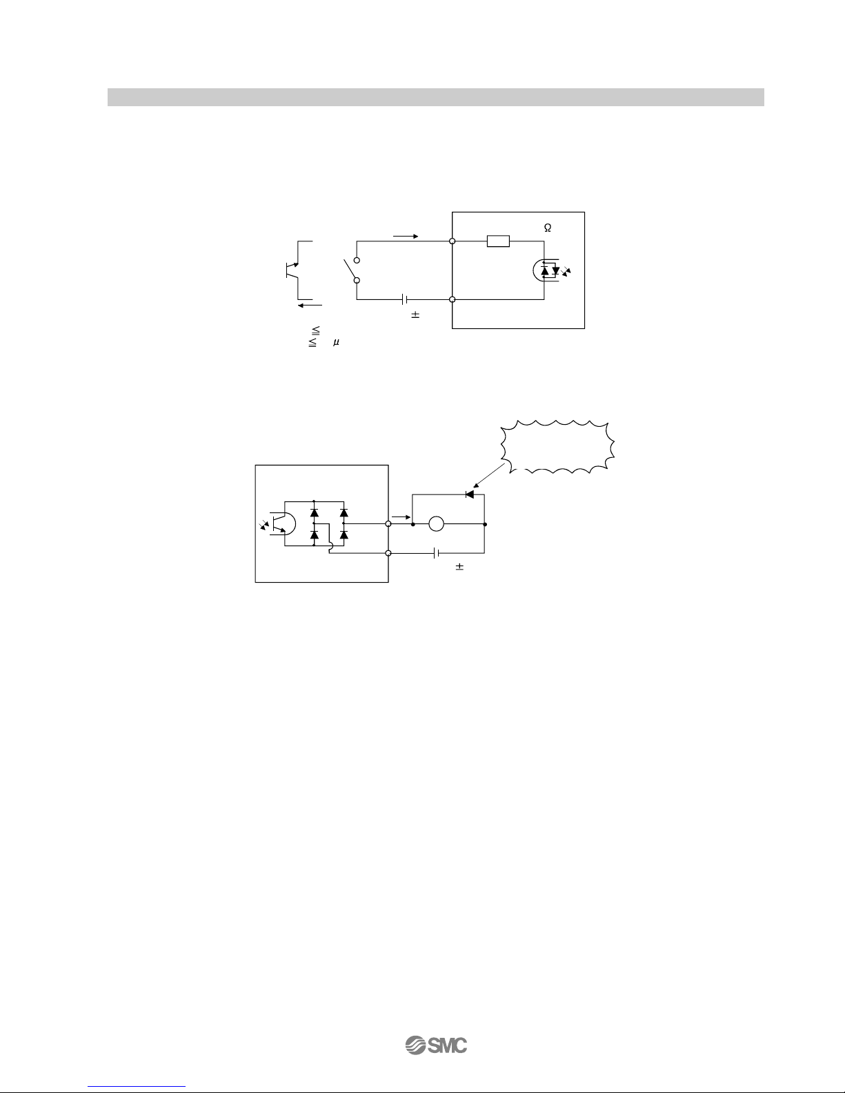
3.2.2 Source I/O interfaces
It is possible to configure the I/O interface for, source type I/O interface. In this case, all (DI-1) input signals and
(DO-1) output signals are of source type. wire according to the following interfaces.
(1) Digital input interface DI-1
EMG,
etc.
Servo amplifier
Switch
Approx. 5mA
DICOM
V
CES
1.0V
I
CEO
100 A
24VDC 10%
150mA
Approx. 5.6k
(2) Digital output interface DO-1
A maximum of 2.6V voltage drop occurs in the driver.
If polarity of diode is
reversed, servo
amplifier will fail.
Servo amplifier
ALM,
etc.
Load
DOCOM
24VDC 10%
150mA
(Note)
Note. If the voltage drop (maximum of 2.6V) interferes with the relay operation, apply higher voltage (up to 26.4V)
from an external source.
Driver
Driver
driver
-15-
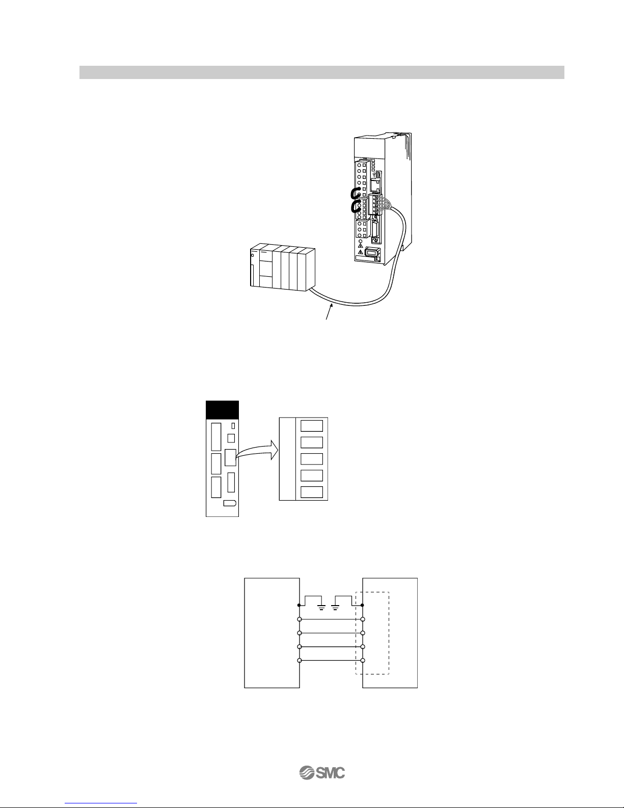
3.3 Wiring of PLC and driver
Connect the PLC and the driver.
(1)Wiring of PLC and driver
Connect the programmable driver CC-Link master unit station and the driver by a twisted cable (3-wire
type).
Programmable controller
CC-Link unit
CC-Link Ver.1.10-compliant cable
(2) Wiring of connector
The pin layout of the communication connector CN1 on the driver unit is shown below.
DA
DG
DB
SLD
FG
Servo amplifier
CN1
CN1
The driver and programmable driver CC-Link master unit are wired as shown below. Refer to “LECSC
Operation Manual”,section 13.4 (3) for the CC-Link Ver.1.10-compliant cable used for connection.
Servo amplifier
SLD
FG
DA
DG
SLD
DB
CN1
FG
DG
DA
DB
Programmable controller
CC-Link master unit
Driver
Driver
CN1 of Mitsubishi Electric System & Service Co., Ltd.
Product number : K05A50230600
-16-
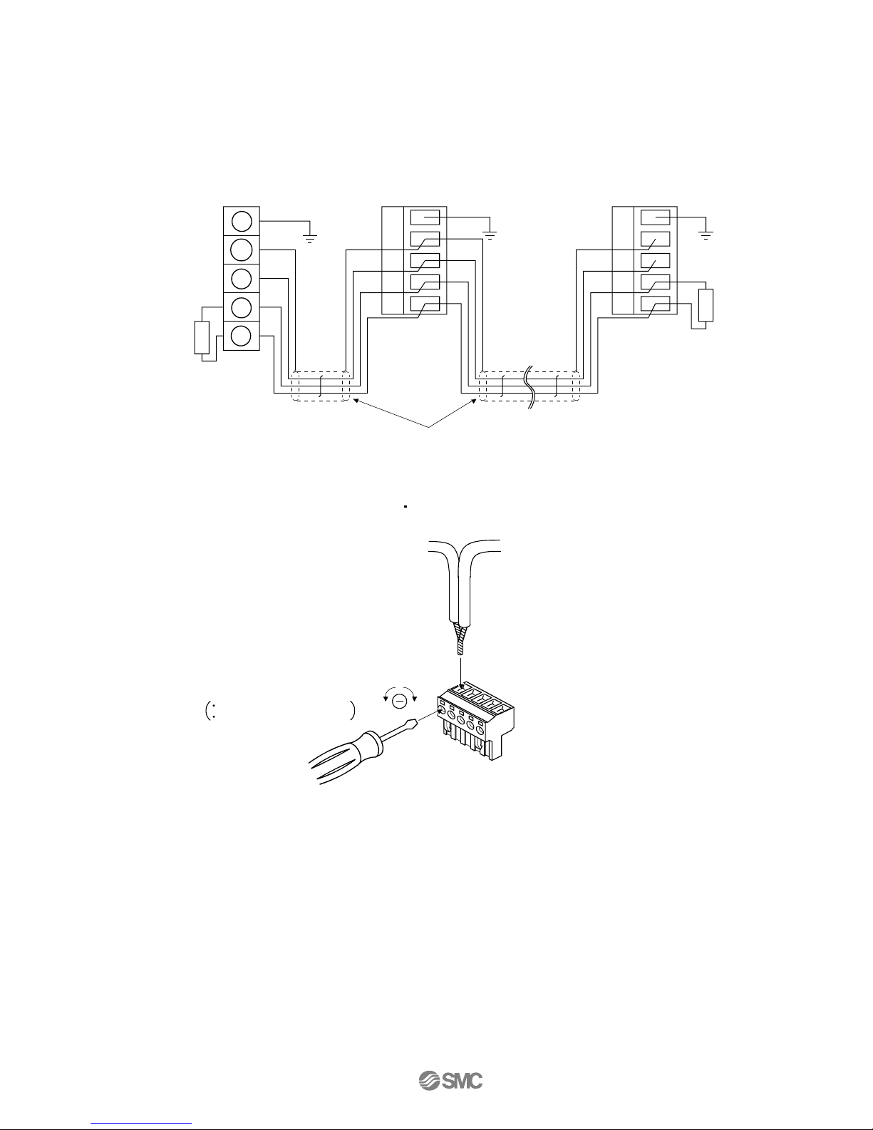
(3) Connecting multiple units
Example for connecting multiple servo units
As the remote I/O stations of CC-Link, drivers share the link system and can be controlled/monitored
using programmable driver user programs.
DB
DA
DG
DB
SLD
FG
DA
DG
DB
SLD
FG
FG
SLD
DG
DA
(Note 2) CC-Link Ver.1.10-compliant cable
MR-J3- T option unit
CC-Link connector (CN1)
(Note 1)
Termination register
MR-J3- T option unit
CC-Link connector (CN1)
Termination register
Programmable controller
CC-Link master unit
(4) Insert the power line
Insert the core of the cable into the opening and tighten it with a flat-blade screwdriver so that it will not
come loose. (Tightening torque: 0.5 to 0.6N m) When inserting the wire into the opening, make sure that
the terminal screw is fully loose.
Loosen
Tighten
CC-Link connector (CN1)
To the next
station
Flat blade screwdriver
Tip thickness 0.4 to 0.6mm
Full wide 2.5 to 3.5mm
To the preceding station or
programmable controller
LECSC□-□
LECSC□-□
-17-
4. Parameter list (Driver side)
Parameters require setting. If necessary, please set the parameters.
Refer to "LECSC Operation Manual”,chapter 6 and "LECSC Operation Manual (Simplified Edition)”,section
5.3 for details.
Refer to "LECSC Operation Manual",chapter 6 for parameters which are not mentioned.
Setup software (MR Configurator2
TM
:LEC-MRC2E) is necessary for the setting of parameter.
*1 Setup software version 1.52E or above is required.
*2 The setup software (MR Configurator2
TM
: LEC-MRC2E) must be purchased as an additional item.
*3 The USB cable (LEC-MR-J3USB) must be purchased as an additional item.
(1) [Basic setting parameters (No.PA□□)]
No.
Symbol
Name
Initial value
Unit
PA01
*STY
Control mode
0000h PA03
*ABS
Absolute position detection system
0000h PA05
*FTY
Feeding function selection
0000h PA06
*CMX
Electronic gear numerator
1 PA07
*CDV
Electronic gear denominator
1 PA08
ATU
Auto tuning mode
0001h PA09
RSP
Auto tuning response
12 PA10
INP
In-position range
100 m PA14
*POL
Rotation direction selection
0
(2) [Extension setting parameters (No. PC□□)]
No.
Symbol
Name
Initial value
Unit
PC02
*ZTY
Home position return type
0000h PC03
*ZDIR
Home position return direction
0001h PC04
ZRF
Home position return speed
500
r/min
PC05
CRF
Creep speed
10
r/min
PC06
ZST
Home position shift distance
0 m PC07
*ZPS
Home position return position data
0
10
STM
m
PC12
JOG
Jog speed
100
r/min
PC24
*COP3
Function selection C-3
0000h
PC30
*DSS
Remote register-based position/speed specifying system
selection
0000h
PC31
LMPL
Software limit
0
10
STM
m
PC32
LMPH
PC33
LMNL
Software limit
0
10
STM
m
PC34
LMNH
(3) [I/O setting parameters (No. PD□□)]
Change the allocation of the input/output signal and select the input signal automatic ON.
Refer to "LECSC Operation Manual”, section 6.4 and "LECSC Operation Manual (Simplified Edition)”,
section 5.5 for details.

-18-
5. Parameter Configuration using Setup software (MR Configurator2TM)
This section describes the configuration procedure for main parameters using the setup software (MR
Configurator2TM: LEC-MRC2E). See chapter 6 of the “LECSC Operation Manual” for parameter details.
5.1Setup software (MR Configurator2TM)
*1 Setup software version 1.52E or above is required.
*2 The setup software (MR Configurator2
TM
:LEC-MRC2E) must be purchased as an additional item.
*3 The USB cable (LEC-MR-J3USB) must be purchased as an additional item.
5.1.1 Installation Method
Perform installation according to the “MR Configurator2TM instruction manual” (Manual/ib0300160*.pdf) contained
on the setup software (MR Configurator2TM) CD-ROM. The “MR Configurator2TM” software will be added to the PC.
5.2 Basic driver set-up for Initial Test Drive
Switch on the main circuit power supply (AC100V/AC200V) and controller circuit power supply
(AC100V/AC200V) to the LECSC driver.
When the driver display flashes as shown below, it wires for EMG and ON (state of EMG release (operational)).
When wiring, I/O connector(LE-CSNA) or I/O cable(LEC-CSNA-1) is required.
(EMG (Forced stop) cannot be controlled with CC-Link.)
If the power supply is turned on for the first time, refer to "LECSC Operation Manual”, chapter 5.
-19-
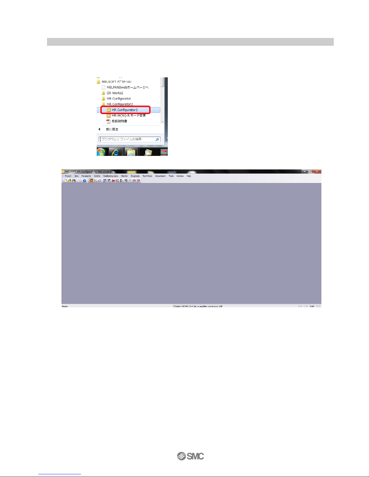
5.2.1 Start up the Setup software (MR Configurator2TM)
① Connect the PC and LECSC using the USB cable.
② Turn on the power of the LECSC.
③ Start application “MR Configurator2”.
Once the application starts, the screen below will be displayed.
-20-
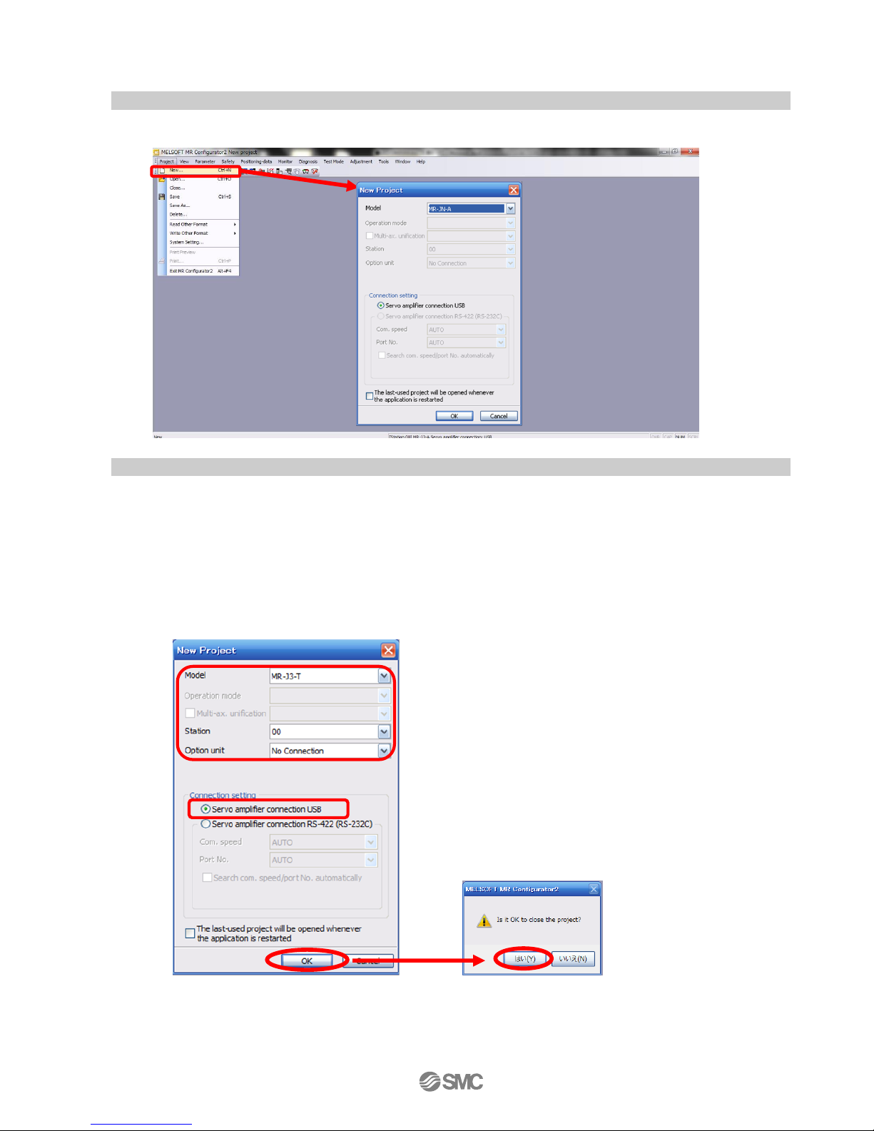
5.2.2 “System Settings”
① From “Project” menu select “New”, the “New project” window will be displayed.
5.2.3 Model Selection
① The Mitsubishi Electric Corporation series will be displayed in the model selection list.
Please select the model “MR-J3-T”, if using the LECSC.
Please select the station for the USB connection. Please to match the value of parameter [PC20] and the
station.
Please select the station “00”, if you want to use for the first time.
Please select the option unit “No Connection”.
② Please select “servo amplifier connection USB” as the communication device.
③ Click OK.
④ Click OK.
①
② ③ ④

-21-
5.2.4 Driver ON LINE Check
Check that the driver is enabled (ONLINE).
Check that the “ONLINE/OFFLINE” icon is displayed “ ”.
It is OFFLINE when displayed as “ ”.
* For OFFLine, PC and amplifier aren’t communicating. Confirm the following points.
- Is amplifier's power supply turning on?
- Are PC and amplifier connected with the USB cable?
- Is the USB driver installed?
- Is the USB driver which is compliant to Windows version installed?
- Is the setting of “Port” for USB connection corresponding?
Please to match the value of parameter [PC20] and the station.
Please select the station “00”, if you want to use for the first time.
Please select the option unit “No Connection”.
5.2.5 Help Function
By selecting “MR Configurator2 Help” in “Help” from any window of the setup software, a “HELP” screen will be
shown.
-22-
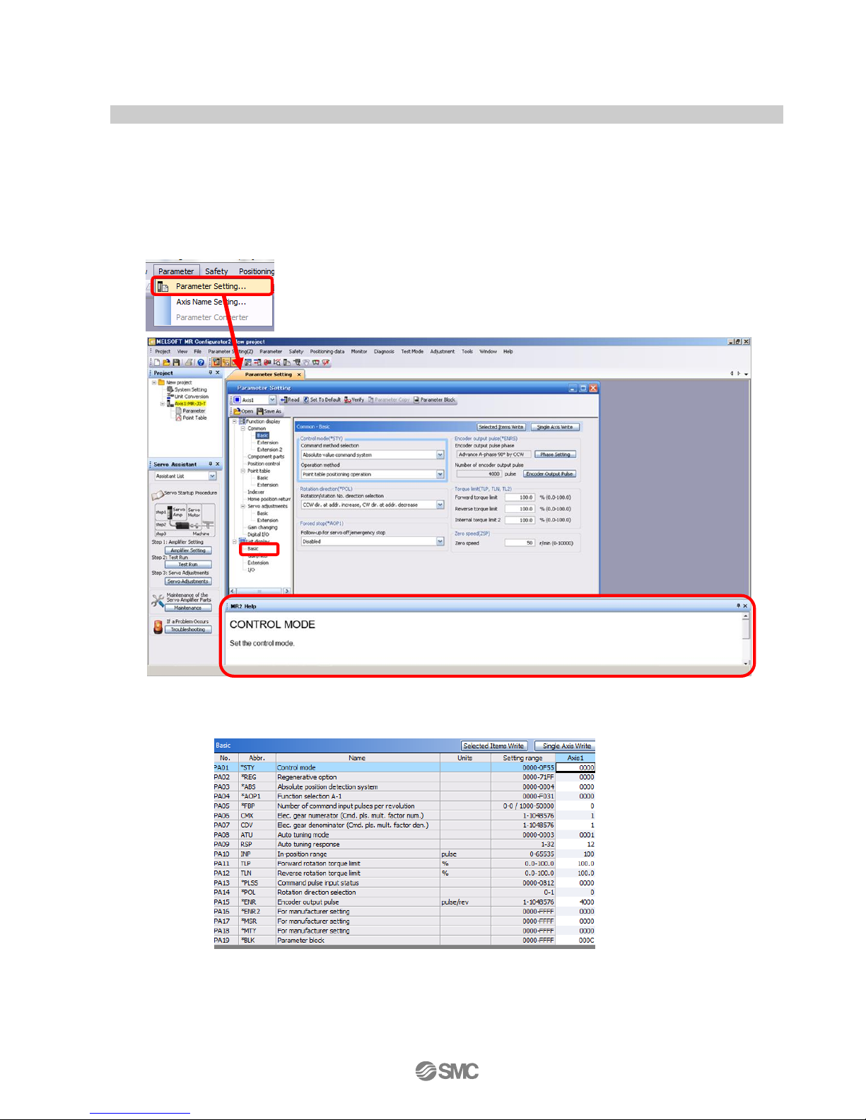
5.3 Parameter Settings (Driver side)
The setup software (MR Configurator2TM:LEC-MRC2E) is necessary for setting the parameter.
*1 Setup software version 1.52E or above is required.
*2 The setup software (MR Configurator2TM:LEC-MRC2E) must be purchased as an additional item.
*3 The USB cable (LEC-MR-J3USB) must be purchased as an additional item.
① From the “Parameter” menu select “Parameter Setting”, the “parameter setting” window will open.
② The explanation of the parameter item is displayed in “MR2 Help”.
(When it is not displayed, from the “View” menu select “Docking window” – “Docking Help”.)
③ When each item of “List display” is clicked, “Parameter list” screen along each item is displayed.
When “Basic” is selected, it is displayed as follows.
Refer to"LECSC Operation Manual”, chapter 6 for details of each parameter.
① ②
③
-23-
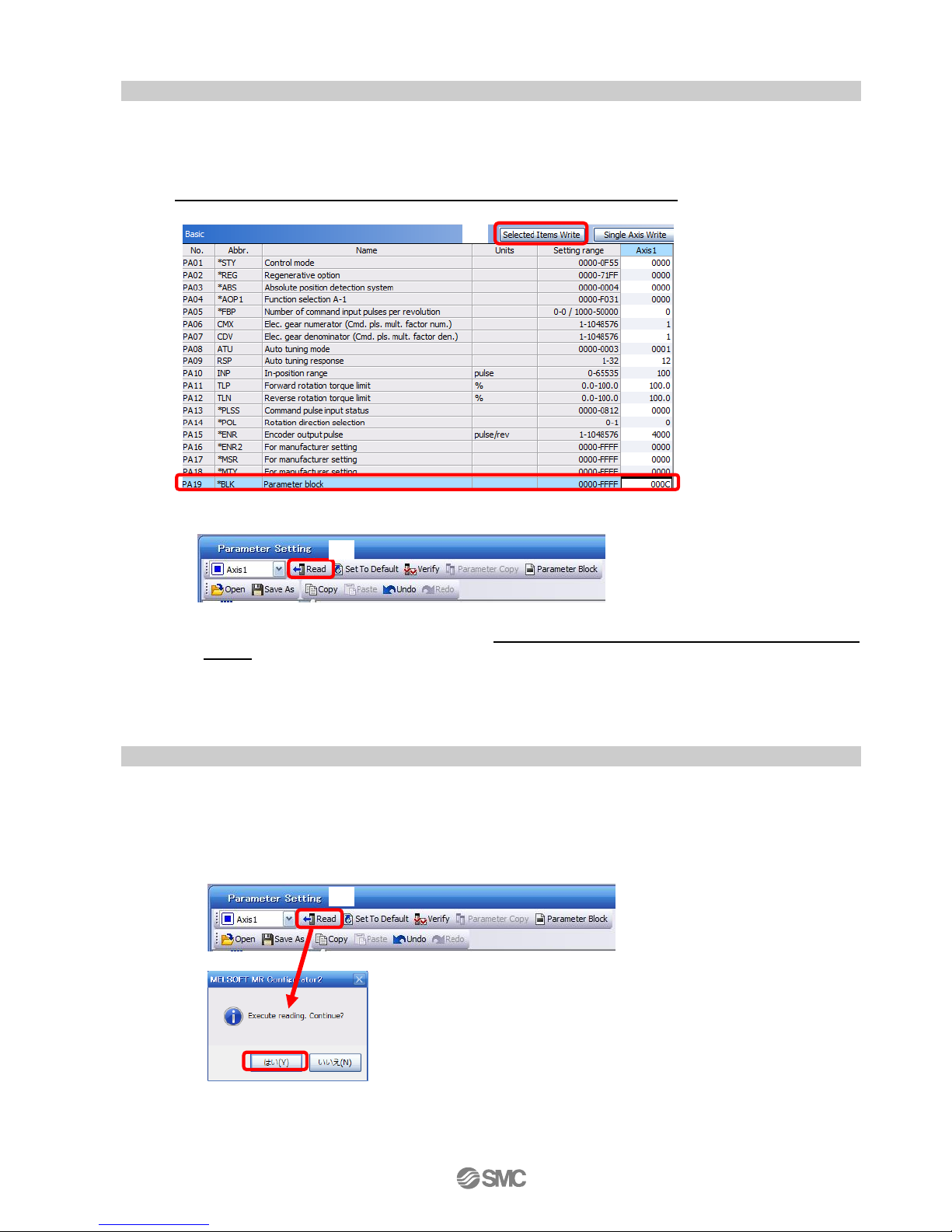
5.3.1 Change of parameter block
To enable settings for all parameters.
① Select “Basic settings (list)” tab and change “PA19” value to “000C”.
② Click the “PA19” row then click “Selected Items Write”.
③ Cycle the power off, then on for parameters for this driver to be enabled.
④ Please click “Read".
When changing of each parameter, note the following points.
Note1) Some of the various parameters, there is "Enable once on again turning the power OFF after
setting". (If you do not the power to OFF, it does not reflect the data in the driver.)
Note2) “Selected Items Write”: It writes the parameter values of the corresponding frame to the driver.
“Single Axis Write”: It writes all of the parameters to the driver.
Note3) Do not change “For manufacturer setting” parameters. If you change by these by mistake, it may cause
the amplifier to not work properly.
5.3.2 Change of parameter block
If you read the parameters of the driver to the software, please do the “read” operation.
① From the View menu bar "parameter (A)" - please click on the "parameter setting (P)". "Parameter
Settings" screen will display.
② Please click on the “Read".
② ② ①
④

-24-
5.3.3 Parameter Configuration Method (Ex. “Control mode” Selection)
Please set the parameters for each actuator.
Please change the parameter values according to usage.
Refer to "LECSC Operation Manual”,chapter 6 for details of each parameter.
Refer to “LECSC Operation Manual (Simplified Edition)”,section 5.4.3 for recommended parameter values for SMC
supplied actuators.
・Setting example of the Control mode (PA01) (in the case of setting to "Absolute value command
system").
① Set the parameters of the PA01 to "0000" in the "Basic" tab.
・Setting example of the Control mode (PA01) (in the case of setting to “Incremental value command
system”).
① Set the parameters of the PA01 to "0001" in the "Basic" tab.
② Click on the "Single Axis Write" button.
③ Turn the power OFFand ON again. The Parameter is then enabled.
When changing of each parameter, note the following points.
Note1) Some of the various parameters, there is "Enable once on again turning the power OFF after setting".
(If you do not the power to OFF, it does not reflect the data in the driver.)
Note2) “Selected Items Write”: It writes the parameter values of the corresponding frame to the driver.
“Single Axis Write”: It writes all of the parameters to the driver.
Note3) Do not change “For manufacturer setting” parameters. If you change by these by mistake, it may cause
the amplifier to not work properly.
①
②
-25-
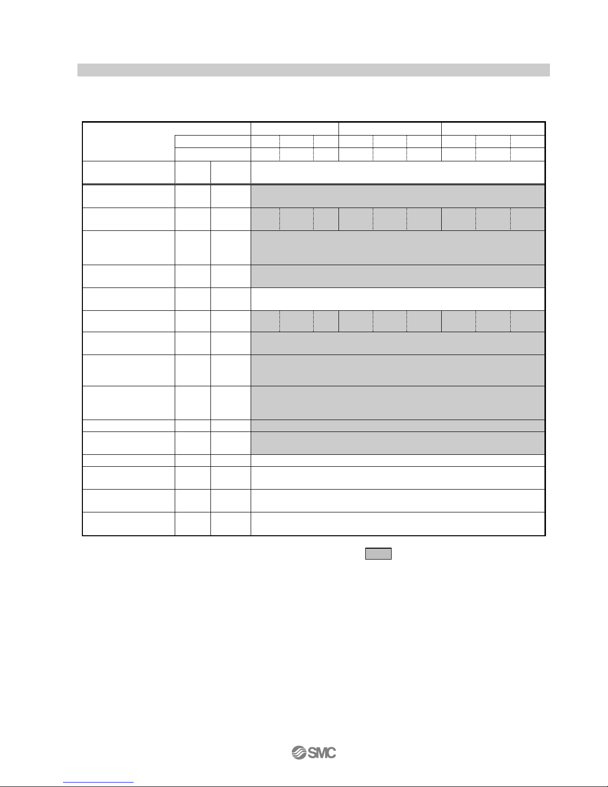
5.3.4 Recommended Parameter Values by Actuator Model
Please change the parameter values according to the customer application. Refer to “LECSC Operation
Manual”,chapter 6 for details.
Recommended Parameter Values [LEF]
Series
LEFS25
LEFS32
LEFS40
Lead symbol
H A B H A B H A B
Lead
20
12 6 24
16 8 30
20
10
Parameter *1,*2
Para.
No.
Initial
value
Recommended value
Electronic gear
numerator *3
PA06
1
32768
Electronic gear
denominator *3
PA07
1
2500
1500
750
3000
2000
1000
3750
2500
1250
Feel length
multiplication (STM)
(Multiplier)
PA05
0000
0000(Less than stroke 1000)/ 0001(Stroke 1000 or more)
Home position return
type
PC02
0000
□□□3(Stopper type)
Home position return
direction
PC03
0001
□□□1 (Motor side)
Home position return
Speed (rpm)
PC04
500
90
150
300
75
113
225
60
90
180
Home position return
position data (μm)
PC07 0 -2000(Less than stroke 1000) / -200(Stroke 1000 or more)
Stopper type home
position return
stopper time (msec)
PC09
100
200
Stopper type home
position return torque
limit value (%)
PC10
15
30
Regenerative option
PA02
0000
0000(Non) / 0002(LEC-MR-RB-032)
Rotation direction
selection *4
PA14
0
1(+:Counter motors side)
Adaptive tuning mode
PB01
0000
0000
Load to motor inertia
moment ratio
PB06
7
7
Machine resonance
suppression filter 1
PB13
4500
4500
Notch shape
selection 1
PB14
0000
0000
Different from the initial value.
*1 Parameter is the recommended value. Please change the parameter to the appropriate value for the
operating method.
*2 A mechanical resonance may occur depending on the configuration or the mounting orientation of the
transferred object. Please change the parameter in the initial setting.
*3 The minimum unit of the travel distance of the actuator should be 1 [μm].
*4. When the motor mounting position is right side parallel (LEFS*R) or left side parallel (LEFS*L), the
rotation direction PA14 selection is 0(+: Counter motors side).
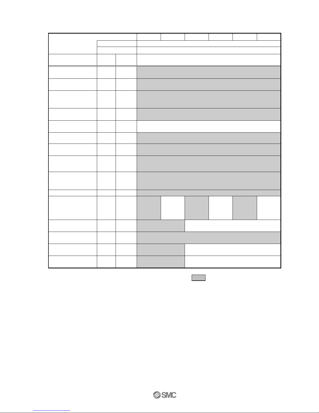
-26-
Series
LEFB25
LEFB25U
LEFB32
LEFB32U
LEFB40
LEFB40U
Lead symbol
S
Lead
54
Parameter *1,*2
Para.
No.
Initial
value
Recommended value
Electronic gear
numerator *3
PA06
1
32768
Electronic gear
denominator *3
PA07
1
6750
Feel length
multiplication (STM)
(Multiplier)
PA05
0000
0000(Less than stroke 1000)/ 0001(Stroke 1000 or more)
Home position return
type
PC02
0000
□□□3(Stopper type)
Home position return
direction
PC03
0001
□□□1 (Motor side)
Home position return
Speed (rpm)
PC04
500
33
Home position return
position data (μm)
PC07 0 -3000(Less than stroke 1000) / -300(Stroke 1000 or more)
Stopper type home
position return
stopper time (msec)
PC09
100
200
Stopper type home
position return torque
limit value (%)
PC10
15
30
Regenerative option
PA02
0000
0000(Non) / 0002(LEC-MR-RB-032)
Rotation direction
selection
PA14
0
1(+:
Counter
motors
side)
0(+:
Counter
motors
side)
1(+:
Counter
motors
side)
0(+:
Counter
motors
side)
1(+:
Counter
motors
side)
0(+:
Counter
motors
side)
★ Adaptive tuning
mode
PB01
0000
0002
0000
★ Load to motor
inertia moment ratio
PB06
7
50
★Machine resonance
suppression filter 1
PB13
4500
400
4500
★ Notch shape
selection 1
PB14
0000
0030
0000
★ Parameter should be changed.
Different from the initial value.
*1 Parameter is the recommended value. Please change the parameter to the appropriate value for the
operating method.
*2 A mechanical resonance may occur depending on the configuration or the mounting orientation of the
transferred object. Please change the parameter in the initial setting.
*3 The minimum unit of the travel distance of the actuator should be 1 [μm].
-27-
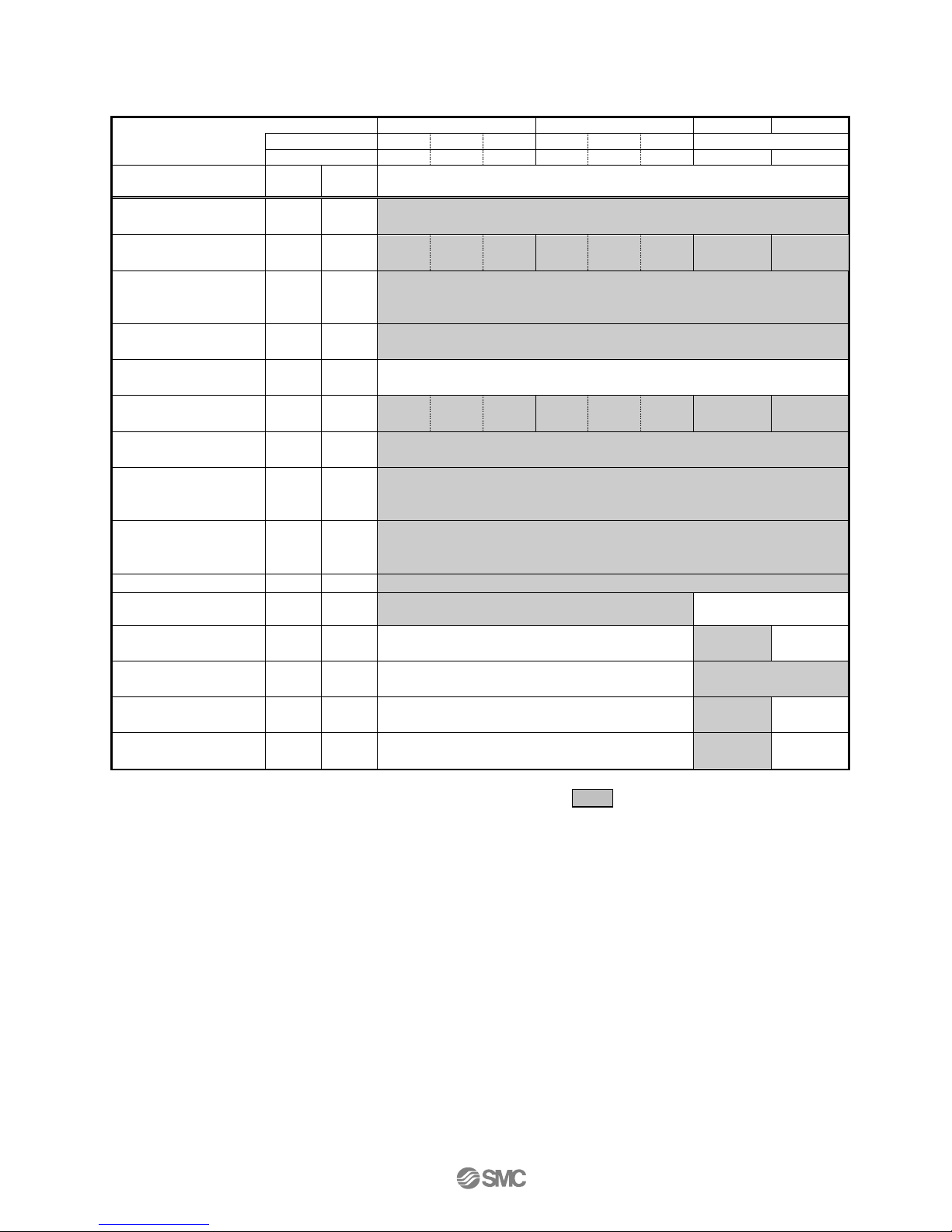
Recommended Parameter Values [LEJ]
Series
LEJS40
LEJS63
LEJB40
LEJB63
Lead symbol
H A B H A
B
T
Lead
24
16 8 30
20
10
27
42
Parameter *1,*2
Para.
No.
Initial
value
Recommended value
Electronic gear
numerator *3
PA06
1
32768
Electronic gear
denominator *3
PA07
1
3000
2000
1000
3750
2500
1250
3375
5250
Feel length
multiplication (STM)
(Multiplier)
PA05
0000
0000(Less than stroke 1000) / 0001(Stroke 1000 or more)
Home position return
type
PC02
0000
□□□3(Stopper type)
Home position return
direction
PC03
0001
□□□1 (Motor side)
Home position return
Speed (rpm)
PC04
500
75
113
225
60
90
180
133
86
Home position return
position data (μm)
PC07
0
-2000(Less than stroke 1000) / -200(Stroke 1000 or more)
Stopper type home
position return
stopper time (msec)
PC09
100
200
Stopper type home
position return torque
limit value (%)
PC10
15
30
Regenerative option
PA02
0000
0000(Non) / 0002(LEC-MR-RB-032) / 0003(LEC-MR-RB-12)
Rotation direction
selection
PA14
0
1
(+:Counter motors side)
0
(+:Counter motors side)
★Adaptive tuning
mode
PB01
0000
0000
0002
0000
★Load to motor inertia
moment ratio
PB06
7
7
50
★Machine resonance
suppression filter 1
PB13
4500
4500
400
4500
★Notch shape
selection 1
PB14
0000
0000
0030
0000
★ Parameter should be changed.
Different from the initial value.
*1 Parameter is the recommended value. Please change the parameter to the appropriate value for the
operating method.
*2 A mechanical resonance may occur depending on the configuration or the mounting orientation of the
transferred object. Please change the parameter in the initial setting.
*3 The minimum unit of the travel distance of the actuator should be 1 [μm].
-28-
Recommended Parameter Values [LEY]
Series
LEY25/LEYG25
LEY25D/
LEYG25D
LEY32/LEYG32
LEY32D/
LEYG32D
Lead symbol
A B C A B C A B C A B C Lead
12 6 3
12 6 3
20
10 5 16 8 4
Parameter *1,*2
Para. No
Initial
value
Recommended value
Electronic gear
numerator *3
PA06
1
32768
Electronic gear
denominator *3
PA07
1
1500
750
375
1500
750
375
2500
1250
625
2000
1000
500
Feel length
multiplication (STM)
(Multiplier)
PA05
0000
0000 (Less than stroke 1000) / 0001 (Stroke 1000 or more)
Home position return
type
PC02
0000
□□□3 (Stopper type)
Home position return
direction
PC03
0001
□□□1 (Motor side)
Home position return
Speed (rpm)
PC04
500
150
300
600
150
300
600
90
180
360
112
225
450
Home position return
position data (μm)
PC07 0 -2000(Less than stroke 1000) / -200(Stroke 1000 or more)
Stopper type home
position return
stopper time (msec)
PC09
100
200
Stopper type home
position return torque
limit value (%)
PC10
15
30
Regenerative option
PA02
0000
0000 (Non)/ 0002 (LEC-MR-RB-032)
Rotation direction
selection *4
PA14
0
0
(
+:Counter
motors side)
1
(+:Counter
motors side )
0
(
+:Counter
motors side)
1
(+:Counter
motors side )
Adaptive tuning
mode
PB01
0000
0000
Load to motor inertia
moment ratio
PB06
7
7
Machine resonance
suppression filter 1
PB13
4500
4500
Notch shape
selection 1
PB14
0000
0000
Different from the initial value.
*1 Parameter is the recommended value. Please change the parameter to the appropriate value for the
operating method.
*2 A mechanical resonance may occur depending on the configuration or the mounting orientation of the
transferred object. Please change the parameter in the initial setting.
*3 The minimum unit of the travel distance of the actuator should be 1 [μm].
*4 When the motor mounting position is right side parallel (LEY*R / LEYG*R) or left side parallel (LEY*L /
LEYG*L), the rotation direction selection is 0(+: Counter motors side).
 Loading...