

SMC Networks LECSB Series, LECSB*-S5 Series, LECSB*-S7 Series, LECSB*-S8 Series Operation Manual

Doc. no. JXC※-OMT0021-B
PRODUCT NAME
AC Servo Motor Driver
MODEL/ Series
LECSB Series
LECSB□-□ Series / Driver
which, if not avoided, could result in minor or
moderate injury.
indicates a hazard w it h a medi um level o f ri sk which , if no t avoid ed, cou ld resul t in death
or serious injury.
k which, if not avoided, will result in death or
serious injury.
Warning
1. The compatibility of the product is the responsibility of the person who designs the equipment or
ntact SMC beforehand and take special consideration of safety measures if the product is to be
1. Safety Instructions
These safety instructions are intended to prevent hazardous situations and/or equipment damage.
These instructions indicate the level of potential hazard with the labels of “Caution,” “Warning” or “Danger.”
They are all important not es f or safety and m ust be followed in add ition to Inter nation al Standards (ISO/IEC)
*1), and other safety regulations.
*1) ISO 4414: Pneumatic flu id power -- General rules relating to systems
ISO 4413: Hydraulic fluid power -- General rules relating to systems
IEC 60204-1: Safety of machinery -- Electrical equipment of machines (Part 1: General requirements)
ISO 10218: Manipulating industrial robots -- Safety
etc.
Caution
Caution indicates a hazard with a low level of risk
Warning
Danger
decides its specifications.
Since the product specified here is used under various operating conditions, its compatibility with specific
equipment mus t be decided b y the per son who designs the equipm ent or dec ides its specific ations bas ed on
necessary analysis and test results.
The expected performance and safety assurance of the equipment will be the responsibility of the person who
has determined its compatibility with the product.
This person should also continuously review all specifications of the product referring to its latest catalog
information, with a view to giving due consideration to any possibility of equipment failure when configuring the
equipment.
2. Only personnel with appropriate training should operate machinery and equipment.
The product specified here may become unsafe if handled incorrectly.
The assembly, operation and maintenance of machines or equipment including our products must be
performed by an operator who is appropriately trained and experienced.
3. Do not service or attempt to remove product an d mac h inery/equipment until safety is confirmed.
The inspection and maintenance of machinery/equipment should only be performed after measures to prevent
falling or runaway of the driven objects have been confirmed.
When the product is to be r emoved, confir m that the safety meas ures as m entioned above ar e implem ented
and the power from any appropriate source is cut, and read and understand the specific product precautions of
all relevant products carefully.
Before machinery/equipment is restarted, take measures to prevent unexpected operation and malfunction.
4. Co
used in any of the following conditions.
1) Conditions and envir onments outside of the given s pecifications , or use outdoors or in a place expos ed to
direct sunlight.
2) Installation on equipment in conjunction with atomic energy, railways, air navigation, space, shipping,
vehicles, military, medical treatment, combustion and recreation, or equipment in contact with food and
beverages, emergenc y stop circuits, clutch and lock circuits in press ap plications, saf ety equipment or other
applications unsuitable for the standard specifications described in the product catalog.
3) An application whic h could have negative ef fects on people, proper ty, or animals r equiring special safet y
analysis.
4) Use in an interlock circuit, which requires the pro vision of double interlock f or possible failure by using a
mechanical protective function, and periodical checks to confirm proper operation.
Note that the CAUTION level may lead to a serious consequence according to conditions. Please follow the
instructions of both levels because they are important to personnel safety.
Warning
Danger indicates a hazard with a high level of ris
A - 1

What must not be done and what must be done are indicated by the following diagrammatic symbols.
Prohibition
Indicates what must not be done. For example, "No Fire" is indicated by
Compulsion
Indicates what must be done. For example, grounding is indicated by
In this Instruction Manual, instructions at a lower level than the above, instructions for other functions, and so on
are classified into "POINT".
After reading this installation guide, always keep it accessible to the operator.
A - 2

Caution
If anything is unclear, contact your nearest sales branch.
Also, even within the warranty period, the wear of a product due to the use of the vacuum pad or
failure due to the deterioration of rubber material are not covered by the limited warranty.
LECSB□-□ Series / Driver
1. Safety Instructions
The product is provided for use in manufacturing industries.
The product herein described is basically provided for peaceful use in manufacturing industries.
If considering using th e product in other indus tries, consult SMC bef orehand and exchang e specifications or a
contract if necessary.
Limited warranty and Disclaimer/Compliance Requirements
The product used is subject to the following “Limited warranty and Disclaimer” and “Compliance
Requirements”.
Read and accept them before using the product.
Limited warran ty and Disclaime r
The warranty period of the product is 1 year in service or 1.5 years after the product is delivered,
whichever is first.*3)
Also, the product may have specified durability, running distance or replacement parts. Please consult
your nearest sales branch.
For any failure or damage reported within the warranty period which is clearly our responsibility, a
replacement product or necessary parts will be provided.
This limited warranty applies only to our product independently, and not to any other damage incurred
due to the failure of the product.
Prior to using SMC products, please read and understand the warranty terms and disclaimers noted in
the specified catalog for the particular products.
*3) Vacuum pads are excluded from this 1 year warranty.
A vacuum pad is a consumable part, so it is warranted for a year after it is delivered.
Compliance Requirem e nt s
When the product is exported, str ictly follow the laws requ ired by the M inistry of Econom y, Trade and I ndustry
(Foreign Exchange and Foreign Trade Control Law).
A - 3
WARNING
CAUTION
1. To prevent electric shock, note the following
Before wiring or inspection, turn off the power and wait for 15 minutes or more (20 minutes or for drive unit
30kW or more) until the charge lamp turns off. Then, confirm that the voltage between P(
and L for drive unit 30kW or more) is safe with a voltage tester and others. Otherwise, an electric
(L
shock may occur. In addition, always confirm from the front of the driver, whether the charge lamp is off or
not.
Connect the driver and servo motor to ground.
Any person who is involved in wiring and inspection should be fully competent to do the work.
Do not attempt to wire the driver and servo motor until they have been installed. Otherwise, you may get
an electric shock.
Operate the switches with dry hand to prevent an electric shock.
The cables should not be damaged, stressed, loaded, or pinched. Otherwise, you may get an electric
shock.
During power-on or operation, do not open the front cover. You may get an electric shock.
Do not operate the driver with the front cover removed. High-voltage terminals and charging area are
exposed and you may get an electric shock.
Except for wiring or periodic inspection, do not remove the front cover even if the power is off. The driver is
charged and y ou may ge t an ele ct r i c sho c k.
) and N( )
2. To prevent fire, note the following
Install the driver, servo motor and regenerative resistor on incombustible material. Installing them directly
or close to combustibles will lead to a fire.
Always connect a magnetic contactor between the main circuit power supply and L1, L2, and L3 of the
driver, and configure the wiring to be able to shut down the power supply on the side of the driver power
supply. If a magnetic contactor is not connected, continuous flow of a large current may cause a fire when
the driver malfunctions.
When a regenerative resistor is used, use an alarm signal to switch main power off. Otherwise, a
regenerative transistor fault or the like may overheat the regenerative resistor, causing a fire.
Provide adequate protection to prevent screws and other conductive matter, oil and other combustible
matter from entering the driver, and servo motor.
Always connect a no-fuse breaker to the power supply of the driver.
A - 4
CAUTION
CAUTION
3. To prevent injury, note the follow
Only the voltage specified in the Instruction Manual should be applied to each terminal, Otherwise, a burst,
damage, etc. may occur.
Connect the terminals correctly to prevent a burst, damage, etc.
Ensure that polarity ( , ) is correct. Otherwise, a burst, damage, etc. may occur.
Take safety measures, e.g. provide covers, to prevent accidental contact of hands and parts (cables, etc.)
with the driver heat sink, regenerative resistor, servo motor, etc. since they may be hot while pow er i s on or
for some time after power-off. Their temperatures may be high and you may get burnt or a parts may
damaged.
During operation, never touch the rotating parts of the servo motor. Doing so can cause injury.
4. Additional instructions
The following instructions should also be fully noted. Incorrect handling may cause a fault, injury, electric shock,
etc.
(1) Transportation and installation
Transport the products correctly according to their mass.
Stacking in excess of the specified number of products is not allowed.
Do not carry the servo motor by the cables, shaft or encoder.
Do not hold the front cover to transport the driver. The driver may drop.
Install the driver in a load-bearing place in accordance with the Instruction Manual.
Do not climb or stand on servo equipment. Do not put heavy objects on equipment.
The driver and servo motor must be installed in the specified direction.
Leave specified clearances between driver and control enclosure walls or other equipment.
Do not install or operate the driver and servo motor which has been damaged or has any parts missing.
Do not block the intake and exhaust areas of the driver and servo motor which has a cooling fan. Doing so
may cause faults.
Do not drop or strike driver or servo motor. Isolate from all impact loads.
Securely attach the servo motor to the machine. If attach insecurely, the servo motor may come off during
operation.
The servo motor with reduction gear must be installed in the specified direction to prevent oil leakage.
Take safety measures, e.g. provide covers, to prevent accidental access to the rotating parts of the servo
motor during operation.
Never hit the servo motor or shaft, especially when coupling the servo motor to the machine. The encoder
may become faulty.
Do not subject the servo motor shaft to more than the permissible load. Otherwise, the shaft may break.
A - 5
CAUTION
Environmental conditions
Driver
Servo motor
In
operation
[ ]
0 to 55 (non-freezing)
0 to 40 (non-freezing)
[ ]
32 to 131 (non-freezing)
32 to 104 (non-freezing)
[ ]
20 to 65 (non-freezing)
15 to 70 (non-freezing)
[ ]
4 to 149 (non-freezing)
5 to 158 (non-freezing)
Ambient
humidity
In operation
90%RH or less (non-condensing)
80%RH or less (non-condensing)
In storage
90%RH or less (non-condensing)
Ambience
Indoors (no direct sunlight) Free from corrosive gas, flammable gas, oil mist, dust and dirt
Altitude
Max. 1000m (3280 ft) above sea level
series
Note. Except the servo motor with redu cti on ge ar.
CAUTION
U
Servo motor
M
V
W
U
V
W
Servo amplifier
(drive unit)
U
M
V
W
U
V
W
Servo motor
Servo amplifier
(drive unit)
When you keep or use it, please fulfill the following environmental conditions.
Item
Ambient
temperature
In storage
LECS□□-S5
LECS□□-S7
LECS□□-S8
X, Y: 49 m/s2
(Note)
Vibration
[m/s
2
]
5.9 or less at 10 to
55Hz (directions of
X, Y and Z axes)
When the equipment has been stored for an extended period of time, contact your local sales office.
(2) Wiring
Wire the equipment correctly and securely. Otherwise, the servo motor may operate unexpectedly.
Do not install a power capacitor, surge absorber or radio noise filter (FR-BIF-(H) : Mitsubishi Electric
Corporation) between the servo motor and driver.
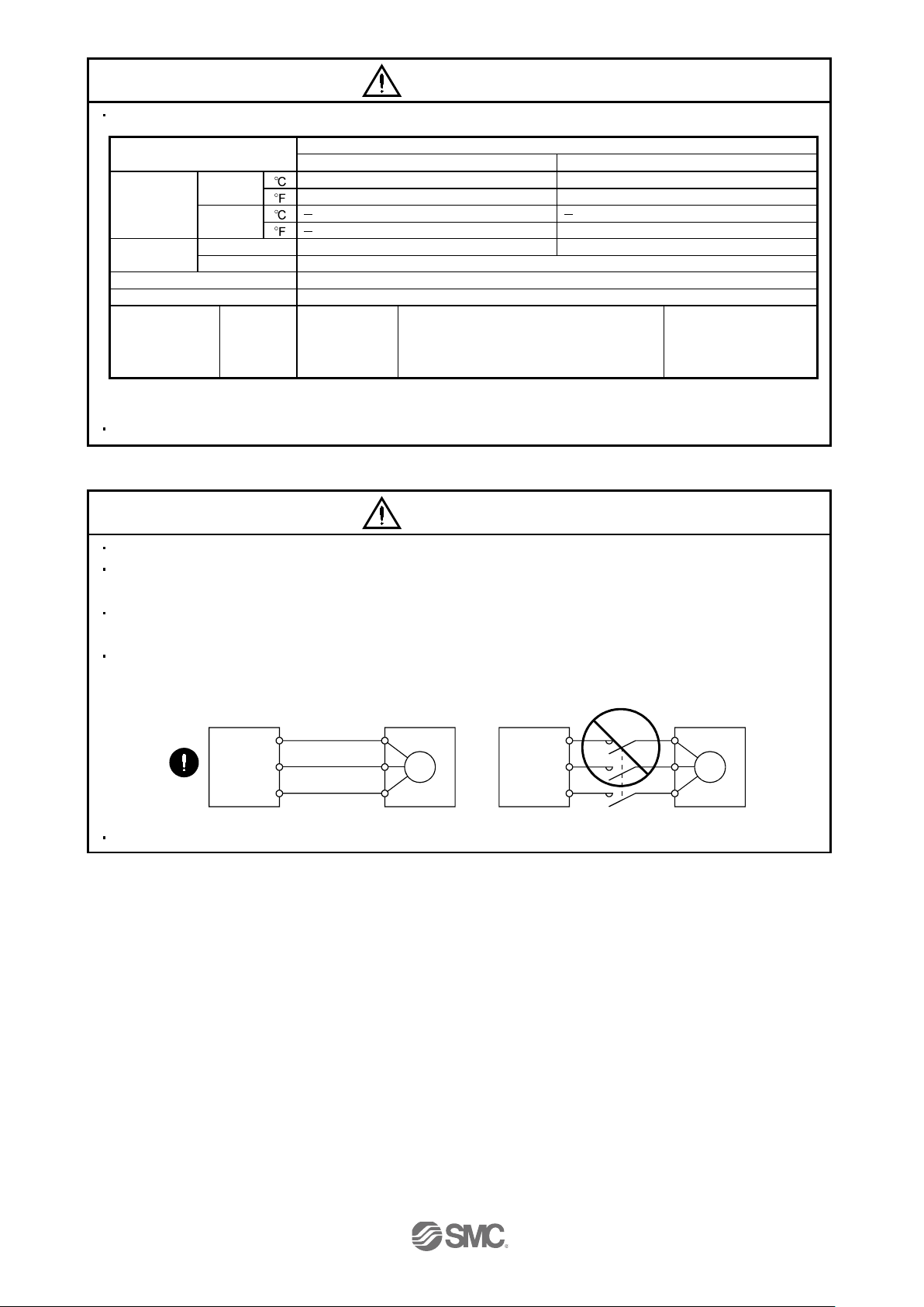
Connect the wires to the correct phase terminals (U, V, W) of the driver and servo motor.
Not doing so may cause unexpected operation.
Connect the servo motor power terminal (U, V, W) to the servo motor power input terminal (U, V, W)
directly. Do not let a magnetic contactor, etc. intervene.
Driver
Driver
Do not connect AC power directly to the servo motor. Otherwise, a fault may occu r.
A - 6
CAUTION
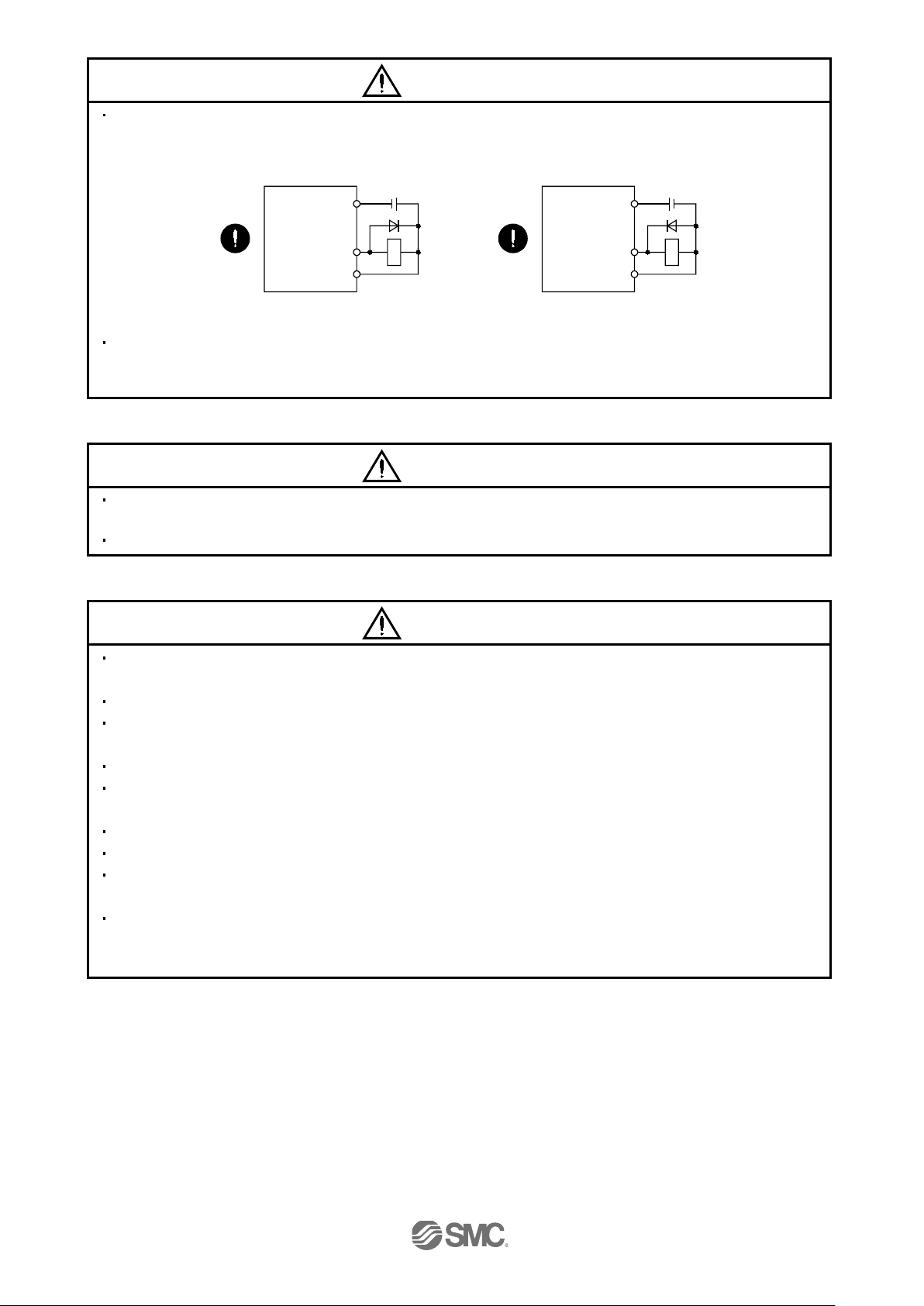
DOCOM
Control output
signal
DICOM
24VDC
Servo amplifier
(drive unit)
RA
For sink output interface
DOCOM
Control output
signal
DICOM
24VDC
Servo amplifier
(drive unit)
RA
For source output interface
CAUTION
CAUTION
The surge absorbing diode installed to the DC relay for control output should be fitted in the specified
direction. Otherwise, the emergency stop and other protective circuits may not operate.
Driver
Driver
When the cable is not tightened enough to the terminal block (connector), the cable or terminal block
(connector) may generate heat because of the poor contact. Be sure to tighten the cable with specified
torque.
(3) Test run adjustment
Before operation, check the parameter settings. Improper settings may cause some machines to perform
unexpected operation.
The parameter settings must not be changed excessively. Operation will be insatiable.
(4) Usage
Provide an external emergency stop circuit to ensure that operation can be stopped and power switched
off immediately.
Any person who is involved in disassembly and repair should be fully competent to do the work.
Before resetting an alarm, make sure that the run signal of the driver is off to prevent an accident. A
sudden restart is made if an alarm is reset with the run signal on.
Do not modify the equipment.
Use a noise filter, etc. to minimize the influence of electromagnetic interference, which may be caused by
electronic equipment used near the driver.
Burning or breaking a driver may cause a toxic gas. Do not burn or break a converter unit and driver.
Use the driver with the specified servo motor.
The lock on the servo motor is designed to hold the motor shaft and should not be used for ordinary
braking.
For such reasons as service life and mechanical structure (e.g. where a ball screw and the servo motor are
coupled via a timing belt), the lock may not hold the motor shaft. To ensure safety, install a stopper on the
machine side.
A - 7

CAUTION
Servo motor
Electromagnetic brake
B
RA
Contacts must be opened
with the EMG stop switch.
Contacts must be opened when ALM
(Malfunction) or MBR (Electromagnetic
brake interlock) turns off.
24 V DC
CAUTION
Lock
(5) Corrective actions
When it is assumed that a hazardous condition may take place at the occur due to a power failure or a
product fault, use a servo motor with a lock or an external lock mechanism for the purpose of prevention.
Do not use the 24VDC interface for the lock. Always use the power supply designed exclusively for the lock.
Otherwise, a fault may occur.
Configure a lock circuit so that it is activated also by an external emergency stop switch.
Contacts must be opened when ALM (Malfunction) and
MBR (Electromagnetic brake interlock) turns off.
Lock
Refer to section 3.11.4 when wiring for the circuit configuration.
When any alarm has occurred, eliminate its cause, ensure safety, and deactivate the alarm before
restarting operation.
When power is restored after an instantaneous power failure, keep away from the machine because the
machine may be restarted suddenly (design the machine so that it is secured against hazard if restarted).
(6) Maintenance, inspection and parts replacement
With age, the electrolytic capacitor of the driver will deteriorate. To prevent a secondary accident due to a
fault, it is recommended to replace the electrolytic capacitor every 10 years when used in general
environment. Please contact your local sales office.
(7) General instruction
To illustrate details, the equipment in the diagrams of this Specifications and Instruction Manual may have
been drawn without covers and safety guards. When the equipment is operated, the covers and safety
guards must be installed as specified. Operation must be performed in accordance with this Specifications
and Instruction Manual.
A - 8

DISPOSAL OF WASTE
Please dispose a driver battery (primary battery) and other options according to your local laws and regulations.
EEP-ROM life
The number of write times to the EEP-ROM, which stores parameter settings, etc., is limited to 100,000. If the
total number of the following operations exceeds 100,000, the converter unit, driver and/or converter unit may
fail when the EEP-ROM reaches the end of its useful life.
Write to the EEP-ROM due to parameter setting changes
Home position setting in the absolute position detection system
Write to the EEP-ROM due to device changes
Precautions for Choosing the Products
SMC will not be held liable for damage caused by factors found not to be the cause of SMC; machine
damage or lost profits caused by faults in the SMC products; damage, secondary damage, accident
compensation caused by special factors unpredictable by SMC; damages to products other than SMC
products; and to other duties.
COMPLIANCE WITH THE EUROPEAN EC DIRECTIVES
Refer to Appendix 9 f or the com plianc e with EC Dir ect ives .
COMPLIANCE WITH UL/ C-UL STANDARD
Refer to Appendix 10 for the compliance with UL/C-UL standard.
<<About the manuals>>
This Instruction Manual are required if you use the General-Purpose AC servo LECSB□-□ for the first time.
Always purchase them and use the LECSB□-□ safely.
<<Wiring>>
Wires mentioned in this instruction manual are selected based on the ambient temperature of 40
(104 ).
A - 9

CONTENTS
1. FUNCTIONS AND CONFIGURATION 1 - 1 to 1 -13
1.1 Summary .................................................................................................................................................. 1 - 2
1.2 Function block diagram ............................................................................................................................ 1 - 3
1.3 Driver standard specifications .................................................................................................................. 1 - 4
1.4 Function list .............................................................................................................................................. 1 - 5
1.4.1 Applicable control mode for each actuator. ...................................................................................... 1 - 7
1.5 Model code definition ............................................................................................................................... 1 - 8
1.6 Combination with servo motor ................................................................................................................ 1 -10
1.7 Structure .................................................................................................................................................. 1 -11
1.7.1 Parts ide nt i fi cati on ............................................................................................................................ 1 -11
1.8 Configuration including auxiliary equipment........................................................................................... 1 -12
2. INSTALLATION 2 - 1 to 2 - 6
2.1 Installation direction and clearances ....................................................................................................... 2 - 3
2.2 Keep out foreign materials ....................................................................................................................... 2 - 4
2.3 Cable stress ............................................................................................................................................. 2 - 5
2.4 Inspection items ....................................................................................................................................... 2 - 5
2.5 Parts having service lives ........................................................................................................................ 2 - 6
3. SIGNALS AND WIRING 3 - 1 to 3 -64
3.1 Input power supply circuit ........................................................................................................................ 3 - 3
3.2 I/O signal connection example ................................................................................................................ 3 - 6
3.2.1 Position control mode ........................................................................................................................ 3 - 6
3.2.2 Speed control mode .......................................................................................................................... 3 - 8
3.2.3 Torque control mode ........................................................................................................................ 3 -10
3.3 Explanation of power supply system ...................................................................................................... 3 -12
3.3.1 Signal ex pl an at io n s .......................................................................................................................... 3 -12
3.3.2 Power-on sequence ......................................................................................................................... 3 -13
3.3.3 CNP1, CNP2, CNP3 wiring method ................................................................................................ 3 -15
3.4 Connectors and signal arrangements .................................................................................................... 3 -20
3.5 Signal explanations ................................................................................................................................. 3 -23
3.6 Detailed description of the signals .......................................................................................................... 3 -34
3.6.1 Position control mode ....................................................................................................................... 3 -34
3.6.2 Speed control mode ......................................................................................................................... 3 -38
3.6.3 Torque control mode ........................................................................................................................ 3 -40
3.6.4 Position/speed control change mode .............................................................................................. 3 -43
3.6.5 Speed/torque control change mode ................................................................................................ 3 -45
3.6.6 Torque/position control change mode ............................................................................................. 3 -47
3.7 Alarm occurrence timing chart ................................................................................................................ 3 -48
3.8 Interfaces ................................................................................................................................................. 3 -49
3.8.1 Internal connection diagram ............................................................................................................ 3 -49
3.8.2 Detailed description of interfaces ..................................................................................................... 3 -50
1

3.8.3 Source I/O interfaces ....................................................................................................................... 3 -55
3.9 Treatment of cable shield external conductor ........................................................................................ 3 -56
3.10 Connection of driver and servo motor .................................................................................................. 3 -57
3.10.1 Connection instructions .................................................................................................................. 3 -57
3.10.2 Power supply cable wiring diagrams ............................................................................................. 3 -58
3.11 Servo motor with a lock......................................................................................................................... 3 -59
3.11.1 Safety precautions ......................................................................................................................... 3 -59
3.11.2 Setting ............................................................................................................................................. 3 -59
3.11.3 Timing charts .................................................................................................................................. 3 -60
3.11.4 Wiring diagrams (LE-□-□ series servo motor) ............................................................................ 3 -62
3.12 Grounding .............................................................................................................................................. 3 -64
4. STARTUP 4 - 1 to 4 -19
4.1 Switching power on for the first time ....................................................................................................... 4 - 2
4.1.1 Startup procedure .............................................................................................................................. 4 - 2
4.1.2 Wiring check ...................................................................................................................................... 4 - 3
4.1.3 Surrounding environment .................................................................................................................. 4 - 4
4.2 Startup in position control mode .............................................................................................................. 4 - 5
4.2.1 Power on and off procedures ............................................................................................................ 4 - 5
4.2.2 Stop .................................................................................................................................................... 4 - 5
4.2.3 Test operation.................................................................................................................................... 4 - 6
4.2.4 Parameter setting .............................................................................................................................. 4 - 7
4.2.5 Actual operation ................................................................................................................................ 4 - 8
4.2.6 Trouble at start-up ............................................................................................................................. 4 - 8
4.3 Startup in speed control mode ................................................................................................................ 4 -10
4.3.1 Power on and off procedures ........................................................................................................... 4 -10
4.3.2 Stop ................................................................................................................................................... 4 -11
4.3.3 Test operation................................................................................................................................... 4 -12
4.3.4 Parameter setting ............................................................................................................................. 4 -13
4.3.5 Actual operation ............................................................................................................................... 4 -14
4.3.6 Trouble at start-up ............................................................................................................................ 4 -14
4.4 Startup in torque control mode ............................................................................................................... 4 -15
4.4.1 Power on and off procedures ........................................................................................................... 4 -15
4.4.2 Stop ................................................................................................................................................... 4 -16
4.4.3 Test operation .................................................................................................................................. 4 -17
4.4.4 Parameter setting ............................................................................................................................. 4 -18
4.4.5 Actual operation ............................................................................................................................... 4 -19
4.4.6 Trouble at start-up ............................................................................................................................ 4 -19
5. PARAMETERS 5 - 1 to 5 -57
5.1 Basic setting parameters (No.PA ) .................................................................................................... 5 - 2
5.1.1 Parameter list .................................................................................................................................... 5 - 2
5.1.2 Parameter write inhibit ...................................................................................................................... 5 - 3
5.1.3 Selection of control mode ................................................................................................................. 5 - 4
5.1.4 Selection of regenerative option ....................................................................................................... 5 - 5
5.1.5 Using absolute position detection system ........................................................................................ 5 - 6
2

5.1.6 Using electromagnetic brake interlock (MBR) .................................................................................. 5 - 6
5.1.7 Number of command input pulses per servo motor revolution ........................................................ 5 - 7
5.1.8 Electronic gear................................................................................................................................... 5 - 8
5.1.9 Auto tuning ....................................................................................................................................... 5 -12
5.1.10 In-position range ............................................................................................................................ 5 -13
5.1.11 Torque limit ..................................................................................................................................... 5 -14
5.1.12 Selection of command pulse input form ........................................................................................ 5 -15
5.1.13 Selection of servo motor rotation direction .................................................................................... 5 -16
5.1.14 Encoder output pulse ..................................................................................................................... 5 -16
5.2 Gain/filter parameters (No. PB
5.2.1 Parameter list ................................................................................................................................... 5 -18
5.2.2 Detail li s t ........................................................................................................................................... 5 -20
5.2.3 Position smoothing ........................................................................................................................... 5 -31
5.3 Extension setting parameters (No. PC
5.3.1 Parameter list ................................................................................................................................... 5 -32
5.3.2 List of d et ail s ..................................................................................................................................... 5 -33
5.3.3 Analog monitor ................................................................................................................................. 5 -43
5.3.4 Alarm history clear ............................................................................................................................ 5 -46
5.4 I/O setting parameters (No. PD
5.4.1 Parameter list ................................................................................................................................... 5 -47
5.4.2 List of d et ail s ..................................................................................................................................... 5 -48
5.4.3 Using forward/reverse rotation stroke end to change the stopping pattern ................................... 5 -57
) ....................................................................................................... 5 -18
) .......................................................................................... 5 -32
)...................................................................................................... 5 -47
6. DISPLAY AND OPERATION SECTIONS 6 - 1 to 6 -23
6.1 Overview ................................................................................................................................................... 6 - 2
6.2 Display sequence ..................................................................................................................................... 6 - 3
6.3 Status display ........................................................................................................................................... 6 - 4
6.3.1 Display transition ............................................................................................................................... 6 - 4
6.3.2 Display examples .............................................................................................................................. 6 - 5
6.3.3 Status display list ............................................................................................................................... 6 - 6
6.3.4 Changi ng the s t atu s disp lay screen .................................................................................................. 6 - 7
6.4 Diagnostic mode ...................................................................................................................................... 6 - 8
6.5 Alarm mode ............................................................................................................................................. 6 -10
6.6 Parameter mode ..................................................................................................................................... 6 -12
6.6.1 Parameter mode transition............................................................................................................... 6 -12
6.6.2 Operation example ........................................................................................................................... 6 -13
6.7 External I/O signal display ...................................................................................................................... 6 -15
6.8 Output si gn al (D O) fo rced ou tp ut............................................................................................................ 6 -18
6.9 Test operation mode ............................................................................................................................... 6 -19
6.9.1 Mode cha ng e .................................................................................................................................... 6 -19
6.9.2 JOG operation .................................................................................................................................. 6 -20
6.9.3 Positioning operation ........................................................................................................................ 6 -21
6.9.4 Motor-less operation ........................................................................................................................ 6 -23
7. GENERAL GAIN ADJUSTMENT 7 - 1 to 7 -11
7.1 Different adjustment methods .................................................................................................................. 7 - 2
3

7.1.1 Adjustment on a single driver ........................................................................................................... 7 - 2
TM
7.1.2 Adjustment using software (MR Configurator2
)............................................................................ 7 - 3
7.2 Auto tuning ............................................................................................................................................... 7 - 4
7.2.1 Auto tuning mode .............................................................................................................................. 7 - 4
7.2.2 Auto tuning mode basis .................................................................................................................... 7 - 5
7.2.3 Adjustment procedure by auto tuning ............................................................................................... 7 - 6
7.2.4 Response level setting in auto tuning mode .................................................................................... 7 - 7
7.3 Manual mode 1 (simple manual adjustment) .......................................................................................... 7 - 8
7.4 Interpolation mode .................................................................................................................................. 7 -11
8. SPECIAL ADJUSTMENT FUNCTIONS 8 - 1 to 8 -18
8.1 Function block diagram ............................................................................................................................ 8 - 2
8.2 Adaptive filter
........................................................................................................................................ 8 - 2
8.3 Machine resonance suppression filter ..................................................................................................... 8 - 5
8.4 Advanced vib r ati o n supp re ss io n co nt rol ................................................................................................. 8 - 7
8.5 Low-pass filter ......................................................................................................................................... 8 -11
8.6 Gain chang in g fu n ction ........................................................................................................................... 8 -11
8.6.1 Applications ...................................................................................................................................... 8 -11
8.6.2 Funct io n bl o ck di ag ram .................................................................................................................... 8 -12
8.6.3 Parameters ....................................................................................................................................... 8 -13
8.6.4 Gain changing procedure ................................................................................................................. 8 -15
8.7 Vibration suppression control filter 2 ...................................................................................................... 8 -17
9. TROUBLESHOOTING 9 - 1 to 9 -26
9.1 Alarms and warning list ............................................................................................................................ 9 - 2
9.2 Remedies for alarms ................................................................................................................................ 9 - 3
9.3 Remedies for warnings ........................................................................................................................... 9 -16
9.4 Troubles without an alarm/warning ........................................................................................................ 9 -18
10. OUTLINE DRAWINGS 10- 1 to 10- 5
10.1 Driver ..................................................................................................................................................... 10- 2
10.2 Connector .............................................................................................................................................. 10- 4
11. CHARACTERISTICS 11- 1 to 11 - 7
11.1 Overload protection characteristics ...................................................................................................... 11- 2
11.2 Power supply equipment capacity and generated loss ....................................................................... 11- 3
11.3 Dynamic brake characteristics .............................................................................................................. 11- 5
11.3.1 Dynamic brake operation ............................................................................................................... 11- 5
11.3.2 The dynamic brake at the load inertia moment ............................................................................. 11- 6
11.4 Cable flexing life .................................................................................................................................... 11- 7
11.5 Inrush currents at power-on of main circuit and control circuit ............................................................ 11- 7
12. OPTIONS AND AUXILIARY EQUIPMENT 12- 1 to 12 -36
12.1 Cable/connector sets ............................................................................................................................ 12- 2
4

12.1.1 Combinations of cable/connector sets .......................................................................................... 12- 3
12.1.2 Encoder cable ................................................................................................................................ 12- 5
12.1.3 Motor cables ................................................................................................................................... 12- 7
12.1.4 Lock cables ..................................................................................................................................... 12- 9
12.2 Regenerative options ........................................................................................................................... 12-10
TM
12.3 Set up software(MR Configurator2
) ................................................................................................. 12-13
12.3.1 Specifications ................................................................................................................................ 12-13
12.3.2 System configuration ..................................................................................................................... 12-14
12.3.3 Precautions for using USB communication function .................................................................... 12-16
12.4 Battery unit LEC-MR-J3BAT ................................................................................................................ 12-17
12.5 Selection example of wires .................................................................................................................. 12-18
12.6 No-fuse breakers, fuses, magnetic contactors ................................................................................... 12-21
12.7 Noise reduction techniques ................................................................................................................. 12-22
12.8 Leakage current breaker ...................................................................................................................... 12-30
12.9 EMC filter (recommended) .................................................................................................................. 12-32
13. COMMUNICATION FUNCTION 13- 1 to 13-35
13.1 Configuration ......................................................................................................................................... 13- 2
13.2 Communication specifications .............................................................................................................. 13- 4
13.2.1 Communication overview ............................................................................................................... 13- 4
13.2.2 Parameter setting ........................................................................................................................... 13- 5
13.3 Protocol ................................................................................................................................................. 13- 6
13.3.1 Transmission data configuration .................................................................................................... 13- 6
13.3.2 Character codes ............................................................................................................................. 13- 7
13.3.3 Error codes ..................................................................................................................................... 13- 8
13.3.4 Checksum ....................................................................................................................................... 13- 8
13.3.5 Time-out.......................................................................................................................................... 13- 9
13.3.6 Retry ............................................................................................................................................... 13- 9
13.3.7 Ini ti al ization .................................................................................................................................... 13-10
13.3.8 Communication procedure example ............................................................................................. 13-10
13.4 Command and data No. list ................................................................................................................. 13-11
13.4.1 Read commands ........................................................................................................................... 13-11
13.4.2 Write commands ........................................................................................................................... 13-15
13.5 Detailed explanations of commands ................................................................................................... 13-17
13.5.1 Data processing ............................................................................................................................ 13-17
13.5.2 Status display ................................................................................................................................ 13-19
13.5.3 Parameters .................................................................................................................................... 13-20
13.5.4 External I/O signal statuses (DIO diagnosis) ............................................................................... 13-23
13.5.5 Input device ON/OFF .................................................................................................................... 13-26
13.5.6 Disable/enable of I/O devices (DIO) ............................................................................................. 13-26
13.5.7 Input devices ON/OFF (test operation) ........................................................................................ 13-27
13.5.8 Test operation mode ..................................................................................................................... 13-28
13.5.9 Output signal pin ON/OFF output signal (DO) forced output ....................................................... 13-31
13.5.10 Alarm history ............................................................................................................................... 13-32
13.5.11 Current alarm .............................................................................................................................. 13-33
13.5.12 Other commands ......................................................................................................................... 13-34
5

14. ABSOLUTE POSITION DETECTION SYSTEM 14- 1 to 14-66
14.1 Outline ................................................................................................................................................... 14- 2
14.1.1 Features.......................................................................................................................................... 14- 2
14.1.2 Restrictions ..................................................................................................................................... 14- 3
14.2 Specifications ........................................................................................................................................ 14- 4
14.3 Battery replacement procedure ............................................................................................................ 14- 5
14.3.1 When replacing battery with the control circuit power ON ............................................................ 14- 5
14.4 Battery installation procedure ............................................................................................................... 14- 5
14.5 Standard connection diagram ............................................................................................................... 14- 6
14.6 Signal explanation ................................................................................................................................. 14- 7
14.7 Startup procedure ................................................................................................................................. 14- 8
14.8 Absolute position data transfer protocol ............................................................................................... 14- 9
14.8.1 Data transfer procedure ................................................................................................................. 14- 9
14.8.2 Transfer method ............................................................................................................................ 14-10
14.8.3 Home position setting.................................................................................................................... 14-21
14.8.4 Use of servo motor with a lock...................................................................................................... 14-23
14.8.5 How to process the absolute position data at detection of stroke end ........................................ 14-25
14.9 Examples of use ................................................................................................................................... 14-26
14.9.1 MELSEC FX
(2N)-32MT (FX(2N)-1PG) ........................................................................................... 14-26
14.9.2 MELSEC A1SD75 ......................................................................................................................... 14-38
14.9.3 MELSEC QD75 ............................................................................................................................. 14-51
14.10 Absolute position data transfer errors ............................................................................................... 14-59
14.10.1 Corrective actions ....................................................................................................................... 14-59
14.10.2 Error resetting conditions ............................................................................................................ 14-61
14.11 Communication-based ABS transfer system .................................................................................... 14-62
14.11.1 Serial communication command ................................................................................................ 14-62
14.11.2 Absolute position data transfer protocol ..................................................................................... 14-62
14.12 Confirmation of absolute position detection data .............................................................................. 14-66
15. SERVO MOTOR 15- 1 to 15- 6
15.1 Servo motor with a lock......................................................................................................................... 15- 2
15.1.1 Features.......................................................................................................................................... 15- 2
15.1.2 Characteristics of servo motor with a lock ..................................................................................... 15- 4
15.2 Protection from oil and water ........................................................................................................ 15- 5
15.3 Cable ............................................................................................................................................. 15- 5
15.4 Rated speed of servo motor ......................................................................................................... 15- 5
15.5 Mounting connectors .................................................................................................................... 15- 6
APPENDIX App.- 1 to App.-13
App. 1 Parameter list ..................................................................................................................................App.- 2
App. 2 Signal layout recording paper ........................................................................................................App.- 4
App. 3 Status display block diagram .........................................................................................................App.- 5
App. 4 Handling of AC driver batteries for the United Nations
Recommendations on the Transport of Dangerous Goods ..........................................................App.- 6
App. 5 Symbol for the new EU Battery Directive ......................................................................................App.- 6
6

App. 6 Compliance with the European EC directives ...............................................................................App.- 7
App. 7 Conformance with UL/C-UL standard .......................................................................................... App.-10
7

1. FUNCTIONS AND CONFIGURATI ON
1. FUNCTIONS AND CONFIGURATION .......................................................................................................... 2
1.1 Summary .................................................................................................................................................. 2
1.2 Function block diagram ............................................................................................................................ 3
1.3 Driver standard specifications .................................................................................................................. 4
1.4 Function list .............................................................................................................................................. 5
1.4.1 Applicable control mode for each actuator. ....................................................................................... 7
1.5 Model code definition ............................................................................................................................... 8
1.6 Combination with servo motor ............................................................................................................... 10
1.7 Structure ................................................................................................................................................. 11
1.7.1 Parts identification ........................................................................................................................... 11
1.8 Configuration including auxiliary equipment .......................................................................................... 12
1 - 1

1. FUNCTIONS AND CONFIGURATION
1. FUNCTIONS AND CONFIGURATIO N
1.1 Summary It has position control, speed control and torque control modes. Further, it can perform operation with the control modes changed, e.g. position/speed control, speed/torque control and torque/position control. Hence, it is applicable to a wide range of fields, not only precision positioning and smooth speed control of machine tools and general industrial machines but also line control and tension control. As this new series has the USB or RS-422 serial communication function, a set up software
TM
(MR Configurator2
operation, status display monitoring, gain adjustment, etc.
With real-time auto tuning, you can automatically adjust the servo gains according to the machine.
The LECSB□-□ series servo motor with an absolute position encoder which has the resolution of 262144
pulses/rev to ensure. Simply adding a battery to the driver makes up an absolute position detection system.
This makes home position return unnecessary at power-on or alarm occurrence by setting a home position
once.
(1) Position control mode
An up to 1Mpps high-speed pulse train is used to control the speed and direction of a motor and execute
precision positioning of 262144 pulses/rev resolution.
The position smoothing function provides a choice of two different modes appropriate for a machine, so a
smoother start/stop can be made in response to a sudden position command.
A torque limit is imposed on the driver by the clamp circuit to protect the power transistor in the main circuit
from overcurrent due to sudden acceleration/deceleration or overload. This torque limit value can be
changed to any value with an external analog input or the parameter.
(2) Speed control mode
An external analog speed command (0 to
speeds) is used to control the speed and direction of a servo motor smoothly.
There are also the acceleration/deceleration time constant setting in response to speed command, the
servo lock function at a stop time, and automatic offset adjustment function in response to external analog
speed command.
(3) Torque control mode
An external analog torque command (0 to
To prevent unexpected operation under no load, the speed limit function (external or internal setting) is also
available for application to tension control, etc.
) installed personal computer or the like can be used to perform parameter setting, test
10VDC) or parameter-driven internal speed command (max. 7
8VDC) is used to control the torque output by the servo motor.
1 - 2
1. FUNCTIONS AND CONFIGURATION
C
D
L
11
CN5 CN3 CN6
I/F
USB RS-422 D/AA/D
USB RS-422
CN4
MR-J3BAT
CN1
P
1
P
2
P
(
) N
(
)
B
NFB
(Note 2)
Power
supply
MC
RA
24VDC
B1
B2
L
1
L
2
L
3
L
21
Servo amplifier
U
V
W
U
V
W
Diode
stack
Regenerative
option
Power factor
improving DC
reactor
CHARGE
lamp
Regenerative TR
(Note 1)
Current
detector
M
Servo motor
Dynamic
brake circuit
Electro-
magnetic
brake
Encoder
Base
amplifier
Voltage
detection
Overcurrent
protection
Current
detection
Control
circuit
power
supply
(Note 3) Cooling fan
Relay
Pulse input
Model position
control
Model speed
control
Virtual
encoder
Virtual
motor
Model
position
Model
speed
Model torque
Actual position
control
Actual speed
control
Current
control
Optional battery
(for absolute position
detection system)
Analog monitor
(2 channels)
Personal
computer
D I/O control
Servo on
Command pulse train input
Start
Failure, etc
.
Analog
(2 channels)
Controller
CN2
Lock
LEC-MR-J3BAT
Driver
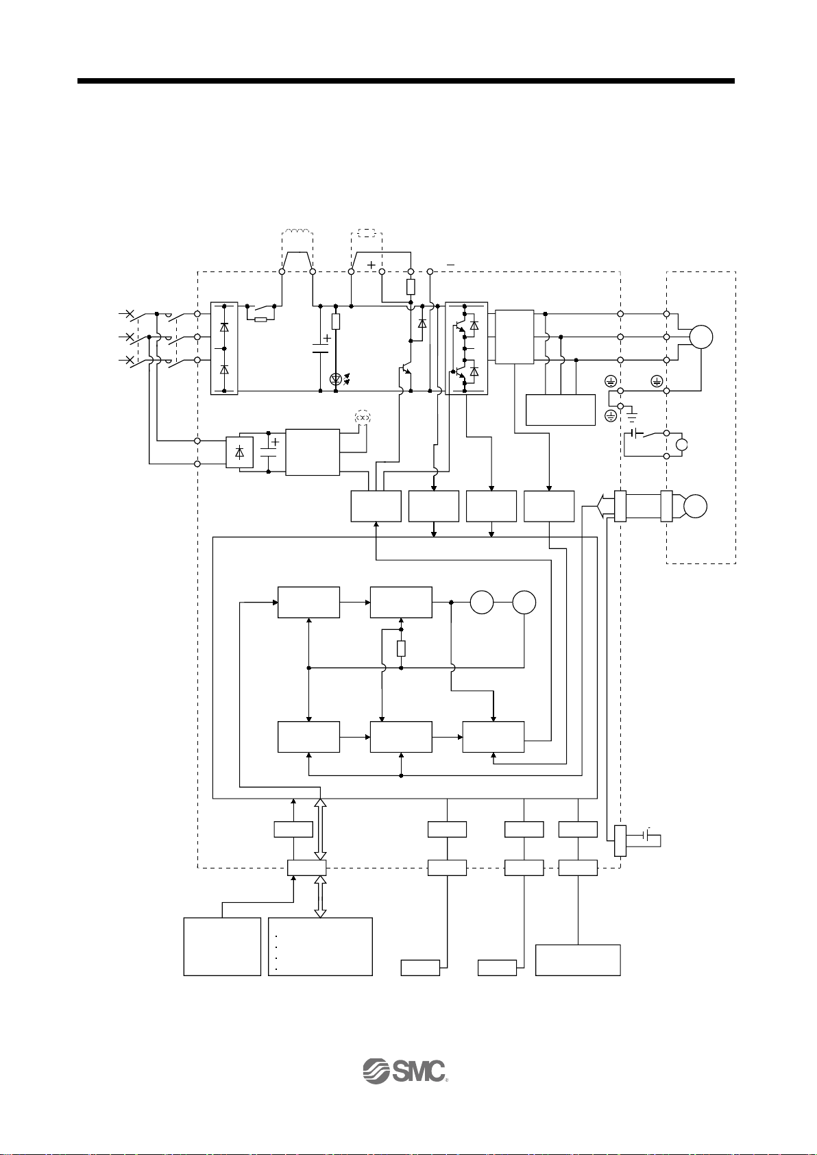
1.2 Function block diagram The function block diagram of this servo is shown below.
(1) LECSB□-□
Note 1. The built-in regenerative resistor is not provided for the LECSB1-S5.
2. For 1-phase 200 to 230VAC, connect the power supply to L1, L2 and leave L3 open.
There is no L
3 for 1-phase 100 to 120VAC power supply. For the specification of power supply, refer to section 1.3.
1 - 3
1. FUNCTIONS AND CONFIGURATION
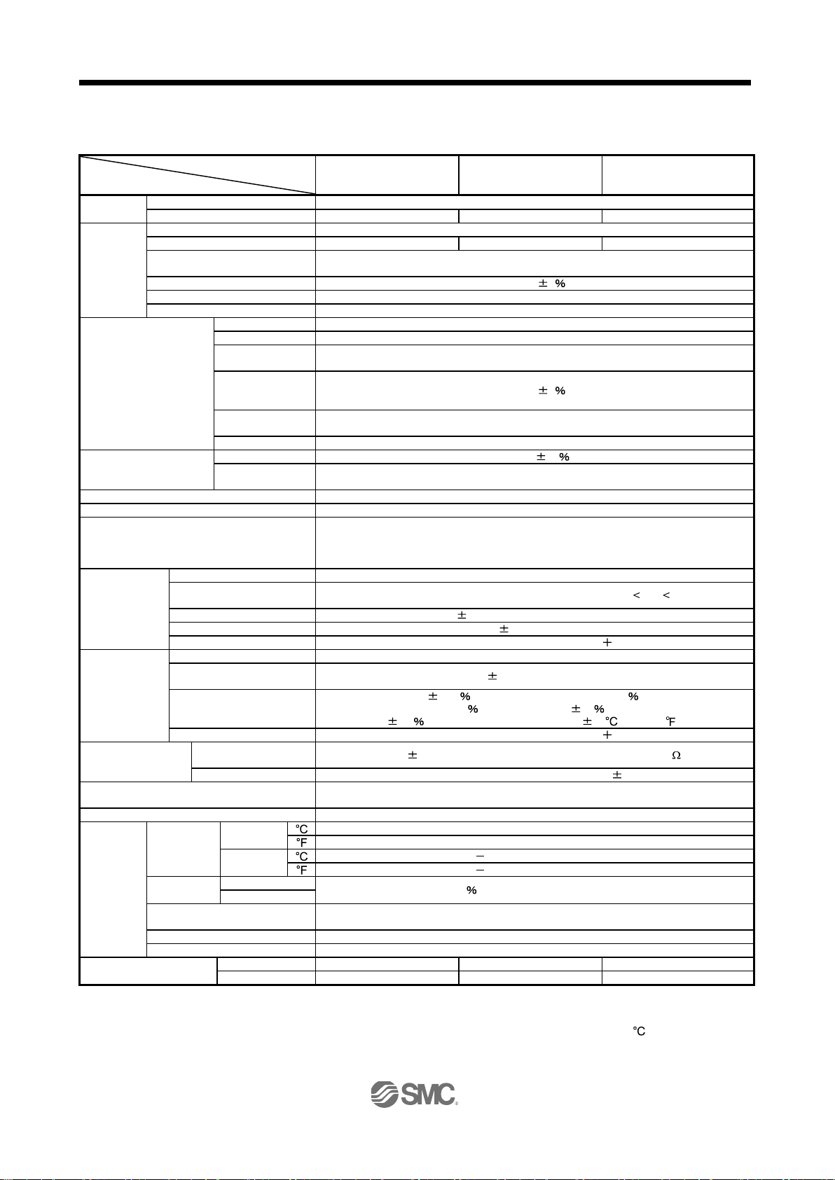
Driver
Item
Output
Rated voltage
3-phase 170VAC
Rated current [A]
1.1
1.5
2.8
Main circuit power
Voltage, frequency
3-phase or 1-phase 200 to 230VAC, 50/60Hz
Rated current [A]
0.9
1.5
2.6
3-phase or 1-phase
170 to 253VAC
Permissible frequency fluctuation
Within 5
Power supply capacity
Refer to section 11.2
Inrush current
Refer to section 11.5
Voltage, frequency
1-phase 200 to 230VAC, 50/60Hz
Rated current [A]
0.2
Permissible voltage
fluctuation
Permissible
fluctuation
Power
consumption [W]
Inrush current
Refer to section 11.5
Voltage
24VDC 10
Power supply
capacity
Control System
Sine-wave PWM control, current control system
Dynamic brake
Built-in
Overcurrent shut-off, regenerative overvoltage shut-off, overload shut-off (electronic
protection, excessive error protection
Position control
Max. input pulse frequency
1Mpps (for differential receiver), 200kpps (for open collector)
Command pulse multiplying
factor
In-position range setting
0 to 10000 pulse (command pulse unit)
Error excessive
3 revolutions
Torque limit
Set by parameter setting or external analog input (0 to 10VDC/maximum torque)
Speed control range
Analog speed command 1: 2000, internal speed command 1: 5000
Analog speed command
input
0.01 or less (load fluctuation 0 to 100 )
0.2 or less (ambient temperature 25 10
(59 to 95 )
)
Torque limit
Set by parameter setting or external analog input (0 to 10VDC/maximum torque)
Torque control
Analog torque command
input
Speed limit
Set by parameter setting or external analog input (0 to 10VDC/Rated speed)
CE (LVD: IEC/EN 50178, EMC: IEC/EN 61800-3)
UL (UL 508C)
Structure
Natural-cooling, open
[ ]
(Note 2) 0 to 55 (non-freezing)
[ ]
(Note 2) 32 to 131 (non-freezing)
[ ]
20 to 65 (non-freezing)
[ ]
4 to 149 (non-freezing)
Ambient
humidity
In operation
In storage
Indoors (no direct sunlight),
Free from corrosive gas, flammable gas, oil mist, dust and dirt
Altitude
Max. 1000m above sea level
Vibration
5.9m/s2 or less at 10 to 55Hz (directions of X, Y and Z axes)
[kg]
0.8
0.8
1.0
[lb]
1.76
1.76
2.21
1.3 Driver standard specifications (1) 200V class
Permissible voltage fluctuation
supply
Control circuit power
supply
Interface power supply
Protective functions
frequency
LECSB□-□
LECSB□-S5 LECSB□-S7 LECSB-□-S8
1-phase 170 to 253VAC
Within 5
30
(Note 1) 0.3A
thermal relay), servo motor overheat protection, encoder error protection, regenerative
error protection, undervoltage, instantaneous power failure protection, overspeed
Electronic gear A:1 to 1048576, B:1 to 1048576, 1/10 A/B 2000
mode
0 to 10VDC / Rated speed
mode
Speed fluctuation ratio
Speed control
mode
Compliance to standards
Ambient
temperature
Ambient
Environmental conditions
Mass
Note 1. 0.3A is the value applicable when all I/O signals are used. The current capacity can be decreased by reducing the number of
I/O points.
2. When closely mounting the driver of 3.5kW or less, operate them at the ambient temperatures of 0 to 45
effective load ratio.
3. When a UL/C-UL-compliant servo motor is used in combination, the value is 2.9A.
In operation
In storage
0 to 8VDC / Maximum torque (input impedance 10 to 12k )
0 (power fluctuation 10 )
90 RH or less (non-condensing)
or at 75% or smaller
1 - 4
1. FUNCTIONS AND CONFIGURATION
(Note)
Control mode
Section 4.2
Section 4.3
Section 3.2.3
Section 4.4
change mode
control and speed control.
mode
control and torque control.
Torque/position control
change mode
Using input device, control can be switched between torque
control and position control.
High-resolution encoder of 262144 pulses/rev is used as a
servo motor encoder.
system
return unnecessary at every power-on.
stop or use an input device to change gains during operation.
suppression control
vibration.
characteristics automatically to suppress mechanical vibration.
system response is increased.
function.
function.
function.
function.
function.
control
stop.
No.PB24
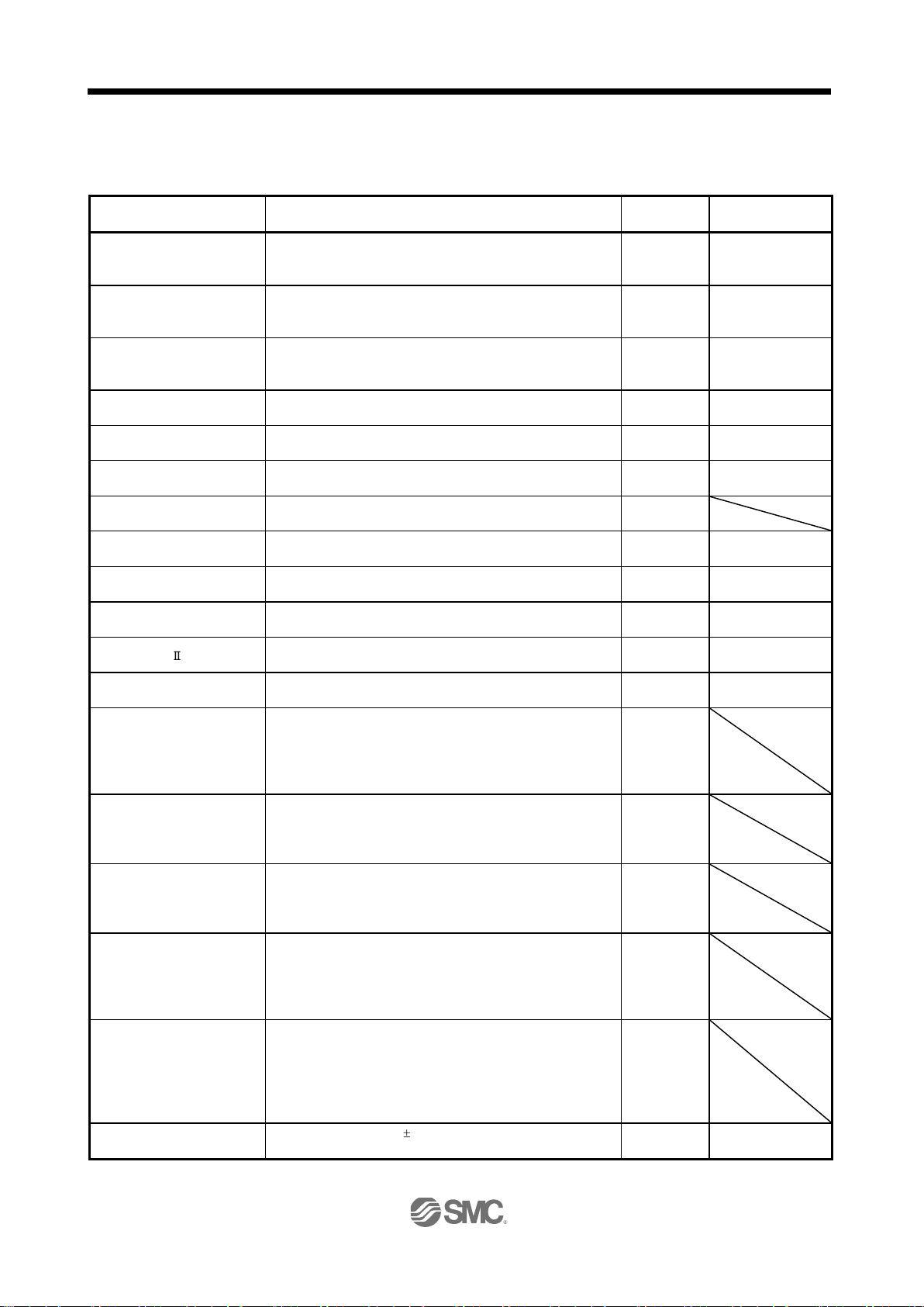
1.4 Function list The following table lists the functions of this servo. For details of the functions, refer to the reference field.
Function Description
Position control mode This servo is used as position control servo. P
Speed control mode This servo is used as speed control servo. S
Torque control mode This servo is used as torque control servo. T
Position/speed control
Speed/torque control change
High-resolution encoder
Absolute position detection
Gain changing function
Advanced vibration
Adaptive filter
Using input device, control can be switched between position
Using input device, control can be switched between speed
Merely setting a home position once makes home position
You can switch between gains during rotation and gains during
This function suppresses vibration at the arm end or residual
Driver detects mechanical resonance and sets filter
P/S Section 3.6.4
S/T Section 3.6.5
T/P Section 3.6.6
P, S, T
P, S Section 8.6
P, S, T Section 8.2
Reference
Section 3.2.1
Section 3.6.1
Section 3.2.2
Section 3.6.2
Section 3.6.3
P Chapter 14
P Section 8.4
Low-pass filter
Machine analyzer function
Machine simulation
Gain search function
Robust disturbance
compensation
Advanced Gain search
Suppresses high-frequency resonance which occurs as servo
Analyzes the frequency characteristic of the mechanical
system by simply connecting a personal computer installed Set
up software(MR Configurator2TM) with a driver.
Set up software(MR Configurator2
Can simulate machine motions on a personal computer screen
on the basis of the machine analyzer results.
Set up software(MR Configurator2
Personal computer changes gains automatically and searches
for overshoot-free gains in a short time.
Set up software(MR Configurator2
This function provides better disturbance response in case of
low response level due to high load inertia moment ratio for the
roll send axes.
Set up software(MR Configurator2
Advanced Gain search automatically searches for the optimum
parameter for settle time to be short.
The gain can be adjusted by setting sequentially in accordance
with wizard screens.
Set up software(MR Configurator2
TM
) is necessary for this
TM
) is necessary for this
TM
) is necessary for this
TM
) is necessary for this
TM
) is necessary for this
P, S, T Section 8.5
P
P
P
P, S, T
P
Slight vibration suppression
Suppresses vibration of 1 pulse produced at a servo motor
1 - 5
P
Parameters

1. FUNCTIONS AND CONFIGURATION
Control mode
Parameters
No.PA06, PA07
to the servo motor shaft varies.
Position smoothing
Speed can be increased smoothly in response to input pulse.
P
Parameter No.PB03
deceleration time constant
regenerative power.
Alarm history clear
Alarm history is cleared.
P, S, T
Parameter No.PC18
restarted by merely switching on the start signal.
different types.
Forward rotation start, reverse rotation start, servo-on (SON)
CN1 connectors.
Parameters
PD10 to PD12
connectors.
PD18
Section 5.1.11
No.PC05 to PC11
Status display
Servo status is shown on the 5-digit, 7-segment LED display
P, S, T
Section 6.3
display.
Use this function for output signal wiring check, etc.
analog speed limit (VLA) of 0V.
for positioning operation and program operation.
Analog monitor output
Servo status is output in terms of voltage in real time.
P, S, T
Parameter No.PC14
(MR Configurator2TM)
status display, etc. can be performed.
output in 3-bit code.
Note. P: Position control mode, S: Speed control mode, T: Torque control mode
P/S: Position/speed control change mode, S/T: Speed/torque control change mode, T/P: Torque/position control change mode
Function Description
Electronic gear Input pulses can be multiplied by 1/50 to 50. P
(Note)
Reference
Auto tuning
S-pattern acceleration/
Return converter
Restart after instantaneous
power failure
Command pulse selection
Input signal selection
(Device settings)
Output signal selection
(Device settings)
Torque limit Servo motor torque can be limited to any value. P, S
Speed limit Servo motor speed can be limited to any value. T
External I/O signal display
Automatically adjusts the gain to optimum value if load applied
Speed can be increased and decreased smoothly. S, T Parameter No.PC03
Used when the regenerative option cannot provide enough
If the input power supply voltage had reduced to cause an
alarm but has returned to normal, the servo motor can be
Command pulse train form can be selected from among three
and other input device can be assigned to certain pins of the
Trouble (ALM), dynamic brake interlock (MBR) and other
output device can be assigned to certain pins of the CN1
ON/OFF statuses of external I/O signals are shown on the
P, S Chapter 7
P, S, T Section 12.4
S Parameter No.PC22
P Section 5.1.12
P, S, T
P, S, T
P, S, T Section 6.7
No.PD03 to PD08,
Parameters
No.PD13 to PD16,
Section 3.6.1 (5)
Section 3.6.3 (3)
Parameter
Output signal (DO)
forced output
Automatic VC offset
Test operation mode
Set up software
Alarm code output
Output signal can be forced on/off independently of the servo
status.
Voltage is automatically offset to stop the servo motor if it does
not come to a stop at the analog speed command (VC) or
JOG operation, positioning operation, motor-less operation,
DO forced output and program operation.
However, Set up software(MR Configurator2
Using a personal computer, parameter setting, test operation,
If an alarm has occurred, the corresponding alarm number is
TM
) is necessary
P, S, T Section 6.8
S, T Section 6.4
P, S, T Section 6.9
P, S, T Section 12.8
P, S, T Section 9.1
1 - 6
1. FUNCTIONS AND CONFIGURATION
(
)
(○:Applicable
Inapplicable)
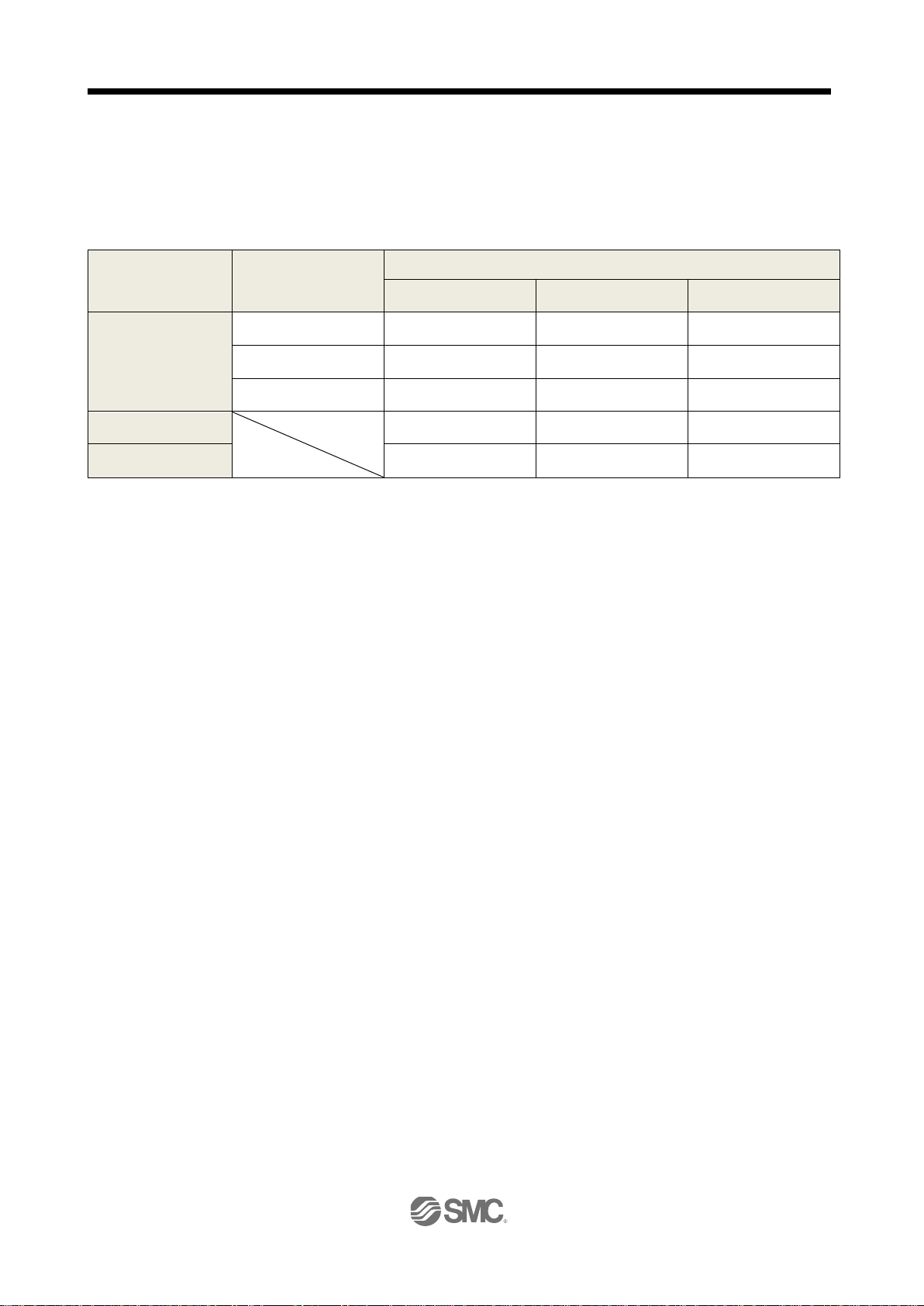
1.4.1 Applicable control mode for each actuator. The following control mode can be selected for applicable actuators. Please refer 「3. SIGNALS AND WIRING」and「5. PARAMETERS」about wiring and parameter setting.
Table. Applicable control mode.
Driver type Actuator type
Control mode
Position control Speed control Torque control
Note 1) 2)
Selected by parameter number PA1.
,×:
LECSB
(
Absolute
)
LEY ○ ○
LEF ○ × ×
Note 2)
○
Note2 )
LEJ ○ × ×
Command method
[Pulse train] [ON/OFF Signal] [ON/OFF Signal]
Operation method
Positioning operation Setting speed operation Setting t orque operation
Note 1. The control change mode cannot be used.
Note 2. Make the moving range limitation by external sensor etc to avoid actuator hitting to the work
piece or stroke end.
When using the thrush control, the following parameter should be set.
If not, it will cause malfunction.
LECSB : The value of the parameter value [PC13] “Analog torque maximum output command”
should be 30 (Maximum thrush of the product) or less. (LEY63 : 50% or less).
When the control equivalent to the pushing operation of the controller LECP series is performed,
select the LECSS / LECSS-T driver and combine it with the Motion or Simple Motion (manufactured
by Mitsubishi Electric Corporation) which has a pushing operation function.
1 - 7
1. FUNCTIONS AND CONFIGURATION
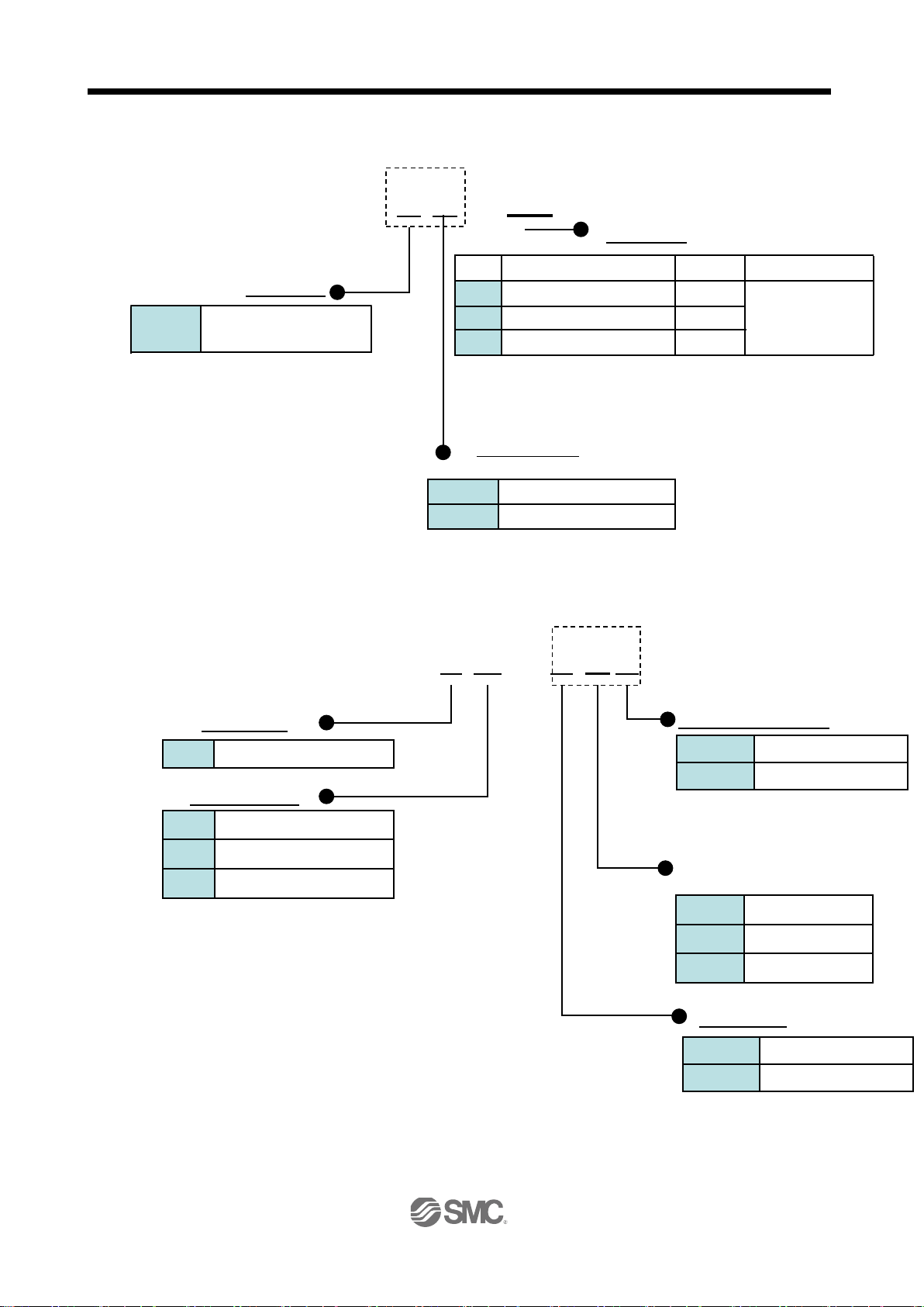
LE
Cable Content
AC Servo motor
S
Encoder cable
E
Lock cable
B
Motor cable
M
Motor Type
2m
2
5m
10m
A
Cable Length (L) [m]
Opposite axis side
B
Axis side
A
Connector Direction
Robot cable
R
Standard cable
S
Cable Type
Motor type
S5
Driver Type
AC200~230V 50,60Hz
AC100~120V 50,60Hz
2
1
Power supply
B
Pulse input type
* If I/O connector(CN1) is required, order the part
number "LEC-CSNB-1" separately.
*1 This is a symbol of motor type (actuator part).
Absolute
S5
S7
Type
Capacity
Encoder
AC Servo motor (S6*1)
AC Servo motor (S7*1)
AC Servo motor (S8*1)
100W
200W
400W
S8*2
1.5 Model code definition (1) Model
(2) Option Model
a) Motor cable / Lock cable / Encoder cable
(Absolute encoder)
LECS
B
1
number "LE-CSNB" separately.
* If I/O cable(CN1) is required, order the part
-
*2 It is correspondence only the power supply voltage "AC200 ~ 230V"
C
S M
-
5
A S
5
1 - 8
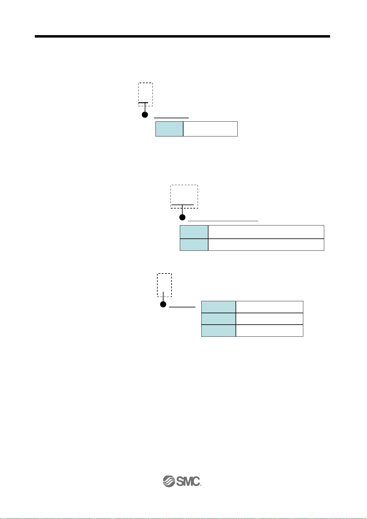
1. FUNCTIONS AND CONFIGURATION
Driver Type
LECSB
B
Regenerative option Type
Permissible regenerative power 100W
12
Permissible regenerative power 30W
032
Languag
English version
E
Japanese version
NIL
Chinese version
C
b) I/O Connector
c)Regenerative option s
d)Setup software (MR Configurator2
Refer to the website of Mitsubishi Electric Corporation for the information of the operating
e)USB cable(3m)
f)Battery
LE-CSNB
*LE-CSNB is 10150-3000PE(
Limited or equivalent goods.
Applicable wire size: AWG24~30
Connector)/10350-52F0-008(Shell kit)of Sumitomo 3M
LEC-MR-RB-032
*MR-RB□ of Mitsubishi Electric
Corporation.
TM
)
LEC-MRC2□
* SW1DNC-MRC2-□ of Mitsubishi Electric Corporation.
environment and upgrading.
Prepare USB cable should be ordered separately.
LEC-MR-J3USB
* MR-J3USBCBL3M of Mitsubishi Electric Corporation.
LEC-MR-J3BAT
* MR-J3BAT of Mitsubishi Electric Corporation.
Battery for replacement.
Absolute position data is maintained by instal lin g the battery to the driver.
1 - 9
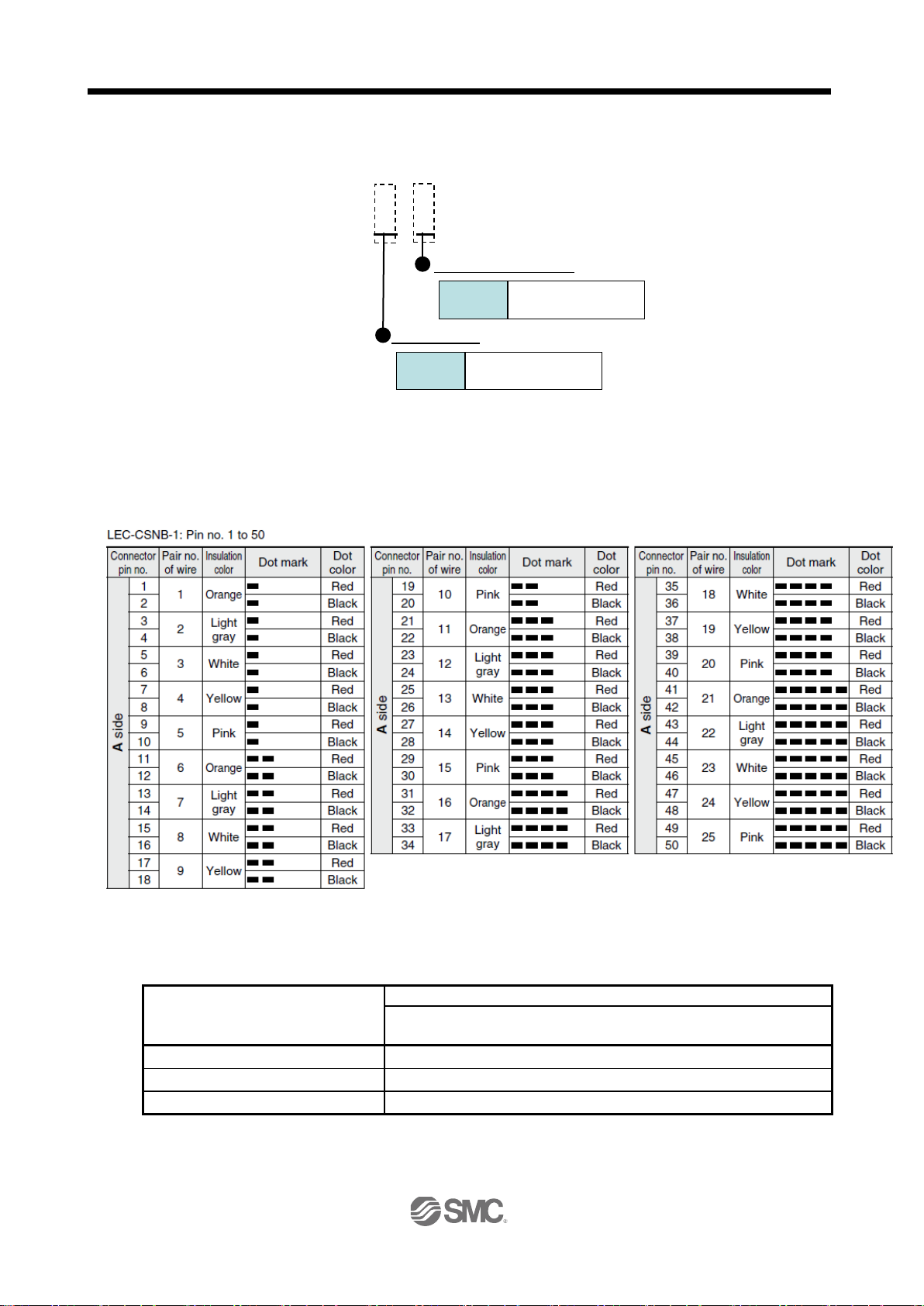
1. FUNCTIONS AND CONFIGURATION
Servo motors
LECSB□-S5
S5,S6
LECSB□-S7
S7
LECSB□-S8
S8
Driver Type
LECSB
B
Cable length(L)[m]
1.5
1
Wiring
g) I/O Cable
1.6 Combination with servo motor The following table lists combinations of driver and servo motors. The same combinations apply to the models with a lock and the models with a reduction gear.
LEC-CSNB-1
*LEC-CSNB-1(Connector/ Shell kit) is 10150-3000PE (Connector)/ 10350-52F0-008(Shell kit)
of Sumitomo 3M Limited or equivalent goods.
Applicable wire size: AWG24
Driver
LE-□-□
1 - 10
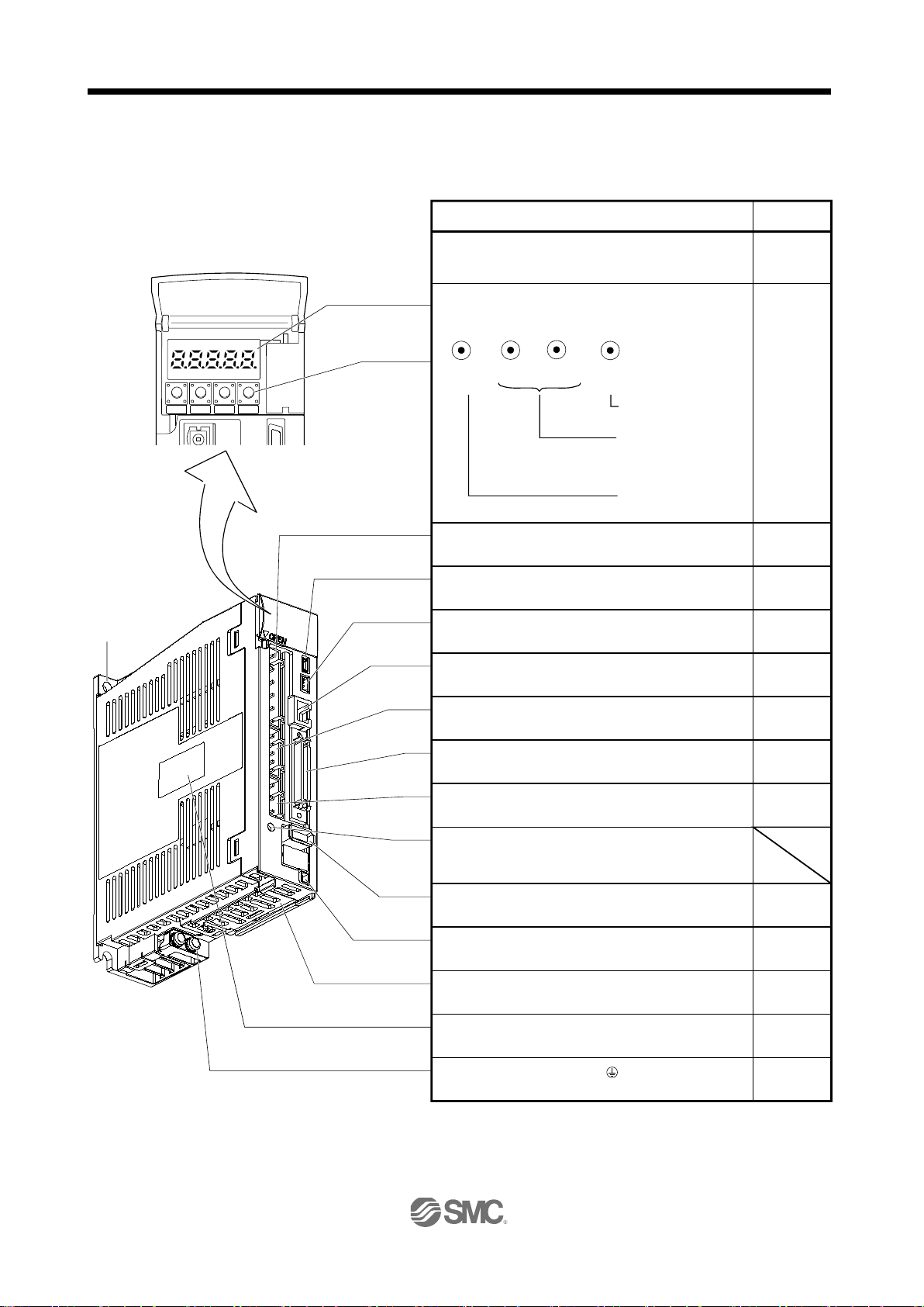
1. FUNCTIONS AND CONFIGURATION
MODE UP DOWN SET
Main circuit power supply connector (CNP1)
Connect the input power supply.
USB communication connector (CN5)
Connect the personal computer.
Analog monitor connector (CN6)
Outputs the analog monitor.
RS-422 communication connector (CN3)
Connect the personal computer.
Control circuit connector (CNP2)
Connect the control circuit power supply/regenerative
option.
I/O signal connector (CN1)
Used to connect digital I/O signals.
Charge lamp
Lit to indicate that the main circuit is charged. While
this lamp is lit, do not reconnect the cables.
Encoder connector (CN2)
Used to connect the servo motor encoder.
Battery holder
Contains the battery for absolute position data backup.
Battery connector (CN4)
Used to connect the battery for absolute position data
backup.
Protective earth (PE) terminal ( )
Ground terminal.
Section 12.8
Section 3.2
Section 3.4
Section 12.8
Chapter 13
Section 3.2
Section 3.4
Section 3.4
Section 12.1
Section 12.9
Chapter 14
Section 14.3
Section 1.5
Fixed part
(2 places)
Servo motor power connector (CNP3)
Connect the servo motor.
Section 3.1
Section 3.3
Section 3.1
Section 3.3
Section 3.1
Section 3.3
Section 3.1
Section 3.3
Rating plate
Name/Application
Display
The 5-digit, seven-segment LED shows the servo
status and alarm number.
Used to set data.
Used to change the
display or data in each
mode.
Used to change the
mode.
MODE
UP
DOWN
SET
Operation section
Used to perform status display, diagnostic, alarm and
parameter setting operations.
Chapter 6
Chapter 6
Detailed
explanation
1.7 Structure
1.7.1 Parts identification (1) LECSB□-□
1 - 11
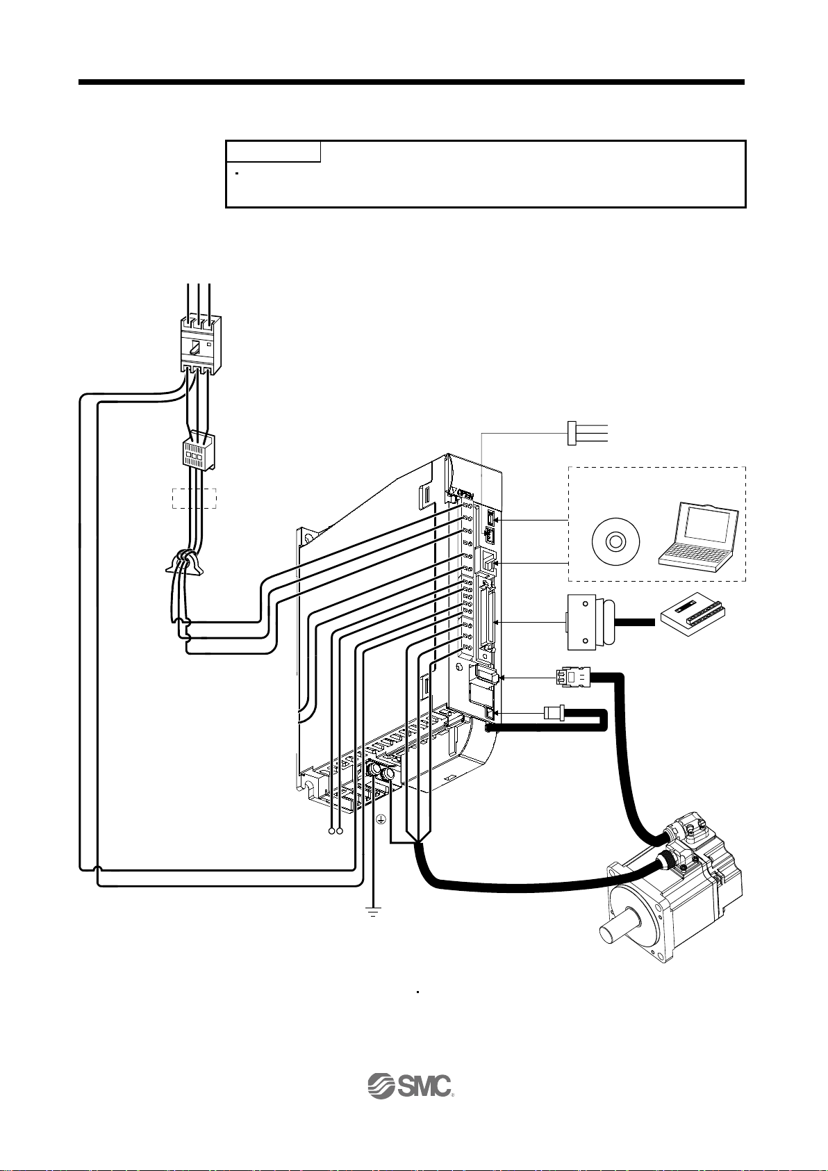
1. FUNCTIONS AND CONFIGURATION
POINT
(Note 3)
Power supply
Line noise filter
(FR-BSF01)
R S T
Magnetic
contactor
(MC)
No-fuse breaker
(NFB) or fuse
CN5
CN3
Regenerative
option
P C
L
11
L
21
Power factor
improving DC
reactor
(FR-BEL)
Analog monitor
CN1
CN2
CN4
Junction terminal block
CN6
P
1
P2
U
V
W
Servo amplifier
Servo motor
(Note 1)
Battery
MR-J3BAT
L
1
L2
L
3
(Note 2)
(Note 2)
MR Configurator
Personal
computer
LEC-MR-J3BAT
Driver
(Mitsubishi
Corporation)
Set up software
Monitor cable(1m)
(Mitsubishi Electric Corporation)
1.8 Configuration including auxiliary equipment
Equipment other than the driver and servo motor are optional or recommended
products.
(1) LECSB□-□
(a) For 3-phase or 1-phase 200 to 230VAC
(MR-J3CN6CBL1M)
Note 1. The battery is used for the absolute position detection system in the position control mode.
Electric
3.For 1-phase 200 to 230VAC, connect the power supply to L
specification.
1 - 12
(MR Configurator2TM)
and leave L3 open. Refer to section 1.3 for the power supply
1 L2
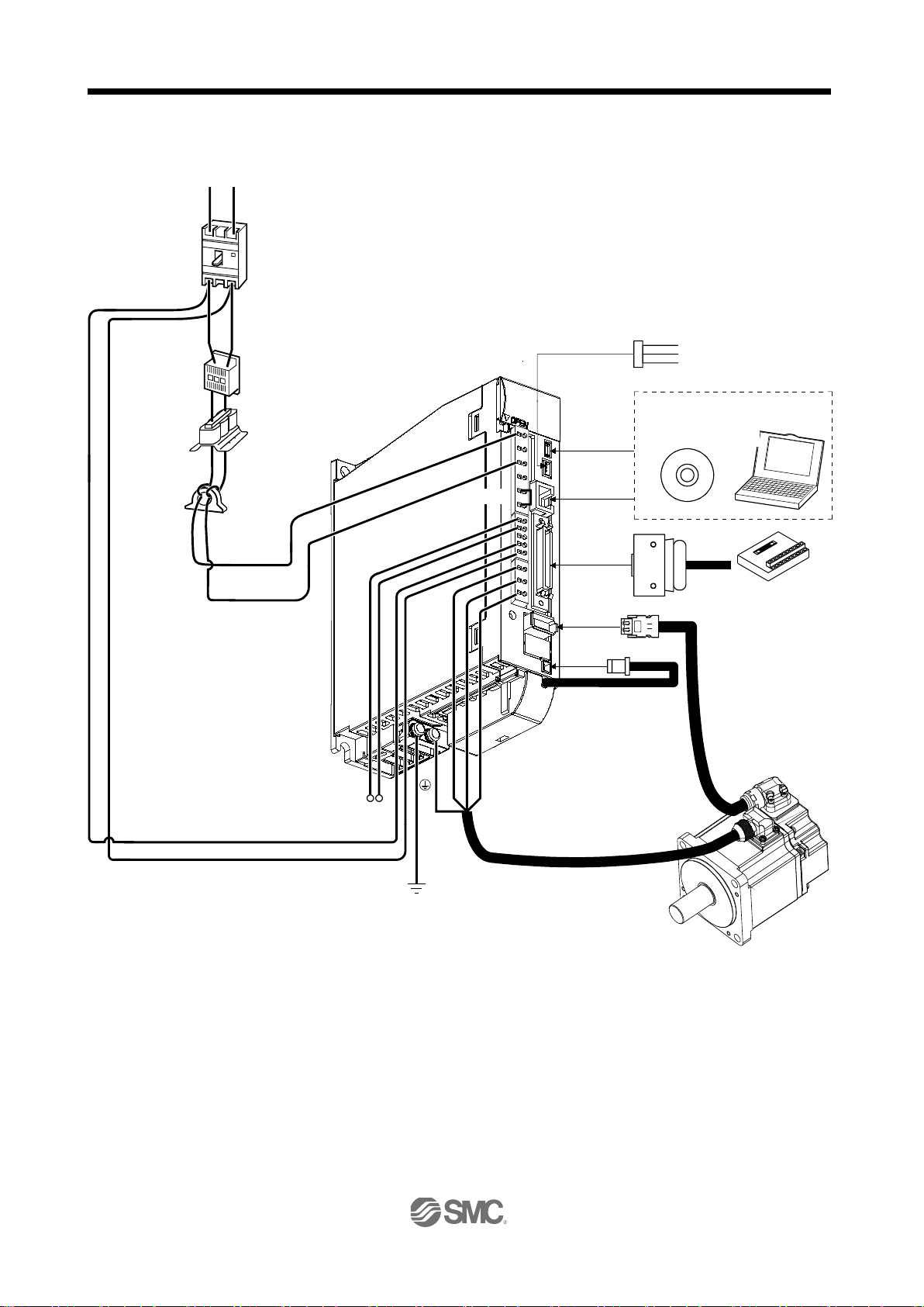
1. FUNCTIONS AND CONFIGURATION
(Note 3
)
Power
supply
Line noise filter
(FR-BSF01)
Magnetic
contactor
(MC)
No-fuse breaker
(NFB) or fuse
CN5
CN
3
Regenerative
option
P C
L
11
L
21
Analog monitor
CN1
CN2
CN4
Junction terminal block
CN6
U
V
W
Servo amplifier
Servo motor
(Note 1)
Battery
MR-J3BAT
L
1
L
2
MR
Configurator
Personal
computer
Power
factor
improving AC
reactor
(FR-BAL)
(Note 2)
R S
LEC-MR-J3BAT
Driver
(Mitsubishi
Corporation)
Set up software
Monitor cable(1m)
(Mitsubishi Electric Corporation)
(b) For 1-phase 100 to 120VAC
Electric
(MR-J3CN6CBL1M)
(MR Configurator2TM)
Note 1. The battery is used for the absolute position detection system in the position control mode.
2. The power factor improving DC reactor cannot be used.
3. Refer to section 1.3 f or t he power supply specification.
1 - 13

2. INSTALLATION
2. INSTALLATION ............................................................................................................................................. 2
2.1 Installation direction and clearances ........................................................................................................ 3
2.2 Keep out foreign materials ....................................................................................................................... 4
2.3 Cable stress ............................................................................................................................................. 5
2.4 Inspection items ....................................................................................................................................... 5
2.5 Parts having service lives ........................................................................................................................ 6
2 - 1

2. INSTALLATION
2. INSTALLATION
WARNING
CAUTION
To prevent electric shock, ground each equipment securely.
Stacking in excess of the limited number of product packages is not allowed.
Install the equipment to incombustibles. Installing them directly or close to
combustibles will led to a fire.
Install the equipment in a load-bearing place in accordance with this Instruction
Manual.
Do not get on or put heavy load on the equipment to prevent injury.
Use the equipment within the specified environmental condition range. (For details
of the environmental condition, refer to section 1.3.)
Provide an adequate protection to prevent screws, metallic detritus and other
conductive matter or oil and other combustible matter from entering the driver.
Do not block the intake and exhaust areas of the driver and servo motor which has a
cooling fan. Doing so may cause faults.
Do not subject the driver to drop impact or shock loads as they are precision
equipment.
Do not install or operate a faulty driver.
When the product has been stored for an extended period of time, contact your local
sales office.
When handling the driver, be careful about the edged parts such as the corners of
the each unit.
The driver must be installed in the metal cabinet (control box).
2 - 2

2. INSTALLATION
Control box
Top
Bottom
Control box
40mm
or more
Servo
amplifier
40mm
or more
10mm or
more
10mm or
more
Wiring
allowance
80mm
Driver
2.1 Installation direction and clearances
The equipment must be installed in the specified direction. Otherwise, a fault may
occur.
CAUTION
Leave specified clearances between the driver and control box inside walls or other
equipment.
(1) LECSB□-□
(a) Installation of one driver
2 - 3

2. INSTALLATION
40mm or more
Control box
100mm or more
40mm or more
10mm
or more
Control box
Leaving clearance
Mounting closely
1mm 1mm
100mm or more
30mm
or more
30mm
or more
30mm
or more
30mm
or more
Top
Bottom
(b) Installation of two or more drivers
POINT
Close mounting is available for the driver of under 3.5kW for 200V class and
400W for 100V class.
Leave a large clearance between the top of the driver and the internal surface of the control box, and
install a cooling fan to prevent the internal temperature of the control box from exceeding the
environmental conditions.
When installing the drivers closely, leave a clearance of 1mm between the adjacent drivers in
consideration of mounting tolerances.
In this case, make circumference temperature into 0 to 45
, or use it at 75 or a smaller effective load ratio.
(2) Others
When using heat generating equipment such as the regenerative option, install them with full consideration
of heat generation so that the driver is not affected.
Install the driver on a perpendicular wall in the correct vertical direction.
2.2 Keep out foreign materials
(1) When installing the unit in a control box, prevent drill chips and wire fragments from entering the driver.
(2) Prevent oil, water, metallic dust, etc. from entering the driver through openings in the control box or a
cooling fan installed on the ceiling.
(3) When installing the control box in a place where there are much toxic gas, dirt and dust, conduct an air
purge (force clean air into the control box from outside to make the internal pressure higher than the
external pressure) to prevent such materials from entering the control box.
2 - 4
2. INSTALLATION
2.3 Cable stress
(1) The way of clamping the cable must be fully examined so that flexing stress and cable's own weight stress
are not applied to the cable connection.
(2) For use in any application where the servo motor moves, fix the cables (encoder, power supply, brake) with
having some slack from the connector connection part of the servo motor to avoid putting stress on the
connector connection part. Use the optional encoder cable within the flexing life range. Use the power
supply and brake wiring cables within the flexing life of the cables.
(3) Avoid any probability that the cable sheath might be cut by sharp chips, rubbed by a machine corner or
stamped by workers or vehicles.
(4) For installation on a machine where the servo motor will move, the flexing radius should be made as large
as possible. Refer to section 11.4 for the flexing life.
(5) The minimum bending radius : Min. 45mm.
2.4 Inspection items
Before starting maintenance and/or inspection, turn off the power and wait for 15
minutes or longer until the charge lamp turns off. Then, confirm that the voltage
between P(
WARNING
electric shock may occur. In addition, always confirm from the front of the driver
whether the charge lamp is off or not.
Any person who is involved in inspection should be fully competent to do the work.
Otherwise, you may get an electric shock.
POINT
) and N( ) is safe with a voltage tester and others. Otherwise, an
Do not test the driver with a megger (measure insulation resistance), or it may
become faulty.
Do not disassemble and/or repair the equipment on customer side.
It is recommended to make the following checks periodically.
(1) Check for loose terminal block screws. Retighten any loose screws.
(2) Check the cables and the wires for scratches and cracks. Perform periodic inspection according to
operating conditions.
2 - 5

2. INSTALLATION
Part name
Life guideline
Smoothing capacitor
10 years
stop times : 100,000 times
Cooling fan
10,000 to 30,000hours (2 to 3 years)
Absolute position battery
Refer to section 14.2
2.5 Parts having service lives
The following parts must be changed periodically as listed below. If any part is found faulty, it must be changed
immediately even when it has n ot yet reach ed the end of its life, whic h depe nds o n the opera ting m ethod an d
environmental conditions.
Number of power-on and number of emergency
Driver
Relay
(1) Smoothing capacitor
Affected by ripple currents, etc. and deteriorates in characteristic. The life of the capacitor greatly depends
on ambient temperature and operating conditions. The capacitor will reach the end of its life in 10 years of
continuous operation in normal air-conditioned environment (40
(104 ) surrounding air temperature or
less).
(2) Relays
Their contacts will wear due to switching currents and contact faults occur. Relays reach the end of their life
when the cumulative number of power-on and emergency stop times is 100,000, which depends on the
power supply capacity.
(3) Driver cooling fan
The cooling fan bearings reach the end of their life in 10,000 to 30,000 hours. Normally, therefore, the
cooling fan must be changed in a few years of continuous operation as a guideline.
It must also be changed if unusual noise or vibration is found during inspection.
2 - 6

3. SIGNALS AND WIRING
3. SIGNALS AND WIRING ................................................................................................................................ 2
3.1 Input power supply circuit ........................................................................................................................ 3
3.2 I/O signal connection example ................................................................................................................. 6
3.2.1 Position control mode ........................................................................................................................ 6
3.2.2 Speed control mode .......................................................................................................................... 8
3.2.3 Torque control mode ....................................................................................................................... 10
3.3 Explanation of power supply system ...................................................................................................... 12
3.3.1 Signal explanations ......................................................................................................................... 12
3.3.2 Power-on sequence ........................................................................................................................ 13
3.3.3 CNP1, CNP2, CNP3 wiring method ................................................................................................ 15
3.4 Connectors and signal arrangements .................................................................................................... 20
3.5 Signal explanations ................................................................................................................................ 23
3.6 Detailed description of the signals ......................................................................................................... 34
3.6.1 Position control mode ...................................................................................................................... 34
3.6.2 Speed control mode ........................................................................................................................ 38
3.6.3 Torque control mode ....................................................................................................................... 40
3.6.4 Position/speed control change mode .............................................................................................. 43
3.6.5 Speed/torque control change mode ................................................................................................ 45
3.6.6 Torque/position control change mode ............................................................................................. 47
3.7 Alarm occurrence timing chart ............................................................................................................... 48
3.8 Interfaces ............................................................................................................................................... 49
3.8.1 Internal connection diagram ............................................................................................................ 49
3.8.2 Detailed description of interfaces .................................................................................................... 50
3.8.3 Source I/O interfaces ....................................................................................................................... 55
3.9 Treatment of cable shield external conductor ........................................................................................ 56
3.10 Connection of driver and servo motor .................................................................................................. 57
3.10.1 Connection instructions ................................................................................................................. 57
3.10.2 Power supply cable wiring diagrams ............................................................................................. 58
3.11 Servo motor with a lock ........................................................................................................................ 59
3.11.1 Safety precautions ......................................................................................................................... 59
3.11.2 Setting ........................................................................................................................................... 59
3.11.3 Timing charts ................................................................................................................................. 60
3.11.4 Wiring diagrams (LE-□-□ series servo motor) ............................................................................... 62
3.12 Grounding ............................................................................................................................................ 64
3 - 1

3. SIGNALS AND WIRING
DOCOM
Control output
signal
DICOM
24VDC
Servo amplifier
RA
For sink output interface
DOCOM
Control output
signal
DICOM
24VDC
Servo amplifier
RA
For source output interface
Controller
Controller
Driver
Driver
3. SIGNALS AND WIRING
Any person who is involved in wiring should be fully competent to do the work.
Before wiring, turn off the power and wait for 15 minutes or longer until the charge
lamp turns off. Then, confirm that the voltage betwee n P(
voltage tester and others. Otherwise, an electric shock may occur. In addition,
WARNING
always confirm from the front of the driver whether the charge lamp is off or not.
Ground the driver and the servo motor securely.
Do not attempt to wire the driver and servo motor until they have been installed.
Otherwise, you may get an electric shock.
The cables should not be damaged, stressed excessively, loaded heavily, or
pinched. Otherwise, you may get an electric shock.
Wire the equipment correctly and securely. Otherwise, the servo motor may operate
unexpected resulting in injury.
Connect cables to correct terminals to prevent a burst, fault, etc.
Ensure that polarity ( , ) is correct. Otherwise, a burst, damage, etc. may occur.
The surge absorbing diode installed to the DC relay for control output should be
fitted in the specified direction. Otherwise, the emergency stop and other protective
circuits may not operate.
) and N( ) is safe with a
CAUTION
Use a noise filter, etc. to minimize the influence of electromagnetic interference,
which may be given to electronic equipment used near the driver.
Do not install a power capacitor, surge killer or radio noise filter (FR-BIF-(H) :
Mitsubishi Electric Corporation) with the power line of the servo motor.
When using the regenerative resistor, switch power off with the alarm signal.
Otherwise, a transistor fault or the like may overheat the regenerative resistor,
causing a fire.
Do not modify the equipment.
During power-on, do not open or close the motor power line. Otherwise, a
malfunction or faulty may occur.
3 - 2
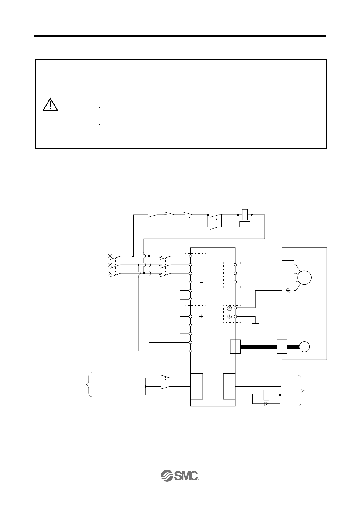
3. SIGNALS AND WIRING
Trouble
(
OFF
Driver
3.1 Input power supply circuit
Always connect a magnetic contactor between the main circuit power and L1, L2,
3 of the driver, and configure the wiring to be able to shut down the power
and L
supply on the side of the driver’s power supply. If a magnetic contactor is not
connected, continuous flow of a large current may cause a fire when the driver
malfunctions.
CAUTION
Use the trouble (ALM) to switch power off. Otherwise, a regenerative transistor fault
or the like may overheat the regenerative resistor, causing a fire.
Check the model and input the correct voltage for the power supply of the driver.
When a voltage, which exceeds the maximum input voltage of the driver
specifications, is input, the driver malfunctions.
Wire the power supply and main circuit as shown below so that the servo-on (SON) turns off as soon as alarm
occurrence is detected and power is shut off.
A no-fuse breaker (NFB) must be used with the input cables of the power supply.
(1) For 3-phase 200 to 230VAC power supply to LECSB□-□
3-phase
200 to
230VAC
Note 4)
Emergency stop (Note 6)
Servo-on
RA
Emergency stop
(Note 6)
(Note 7)
MCNFB
(Note 1)
(Note 2)
ON
MC
Servo amplifier
CNP1
L
1
L2
L3
N( )
P
1
P
2
CNP2
P( )
C
D
L11
L
21
CN1 CN1
EMG
SON
DOCOM
CNP3
PE
CN2
DOCOM
DICOM
ALM
U
V
W
MC
SK
(Note 5)
(Note 3)
Encoder cable
24VDC
RA
Servo
U
V
W
Trouble
motor
Motor
M
Encoder
(Note 4)
3 - 3

3. SIGNALS AND WIRING
Trouble
(
OFF
Driver
Note 1. Always connect P1 and P2. (Factory-wired.)
2. Always connect P( ) and D. (Factory-wired.) When using the regenerative option, refer to section 12.2.
3. For encoder cable, use of the option cable is recommended. Refer to section 12.1 for selection of the cable.
4. For the sink I/O interface.
For the source I/O interface, refer to section 3.8.3.
5. Refer to section 3.10.
6. Configure the circuit to shut down the main circuit power supply simultaneously with the turn off of emergency
stop (EMG) using the external sequence.
7. Be sure to use a magnetic contactor with an operation delay time of 80ms or less. The operation delay time is
the time interval between current being applied to the coil until closure of contacts.
(2) For 1-phase 200 to 230VAC power supply to LECSB□-□
RA
Emergency stop
(Note 6)
1-phase
200 to
230VAC
(Note 7)
MCNFB
(Note 1)
(Note 2
CNP1
L
L2
L3
N
P
P
CNP2
P
C
)
D
L11
L
ON
MC
MC
SK
Servo motorServo amplifier
1
1
2
21
CNP3
U
V
W
PE
CN2
(Note 5)
(Note 3)
Encoder cable
U
V
W
Motor
M
Encoder
Note 4)
Emergency stop (Note 6)
Servo-on
CN1 CN1
EMG
SON
DOCOM
DOCOM
DICOM
ALM
24VDC
RA
Trouble
(Note 4)
Note 1. Always connect P1 and P2. (Factory-wired.)
2. Always connect P and D. (Factory-wired.) When using the regenerative option, refer to section 12.2.
3. For encoder cable, use of the option cable is recommended. Refer to section 12.1 for selection of the cable.
4. For the sink I/O interface. For the source I/O interface, refer to section 3.8.3.
5. Refer to section 3.10.
6. Configure the circuit to shut down the main circuit power supply simultaneously with the turn off of emergency
stop (EMG) using the external sequence.
7. Be sure to use a magnetic contactor with an operation delay time of 80ms or less. The operation delay time is
the time interval between current being applied to the coil until closure of contacts.
3 - 4

3. SIGNALS AND WIRING
Trouble
(
OFF
Driver
(3) For 1-phase 100 to 120VAC power supply to LECSB□-□
1-phase
100 to
120VAC
Note 4)
Emergency stop (Note 6)
Servo-on
RA
Emergency stop
(Note 6)
(Note 7)
MCNFB
(Note 1)
(Note 2)
ON
MC
CNP1
L
1
Blank
CNP3
L2
N
P
1
P
2
PE
CNP2
P
C
D
CN2
L11
L
21
CN1 CN1
EMG
SON
DOCOM
DOCOM
DICOM
ALM
U
V
W
MC
SK
(Note 5)
(Note 3)
Encoder cable
24VDC
RA
Servo motorServo amplifier
U
V
W
Trouble
Motor
M
Encoder
(Note 4)
Note 1. Always connect P1 and P2. (Factory-wired.) The power factor improving DC reactor cannot be used.
2. Always connect P and D. (Factory-wired.) When using the regenerative option, refer to section 12.2.
3. For encoder cable, use of the option cable is recommended. Refer to section 12.1 for selection of the cable.
4. For the sink I/O interface. For the source I/O interface, refer to section 3.8.3.
5. Refer to section 3.10.
6. Configure the circuit to shut down the main circuit power supply simultaneously with the turn off of emergency
stop (EMG) using the external sequence.
7. Be sure to use a magnetic contactor with an operation delay time of 80ms or less. The operation delay time is
the time interval between current being applied to the coil until closure of contacts.
3 - 5
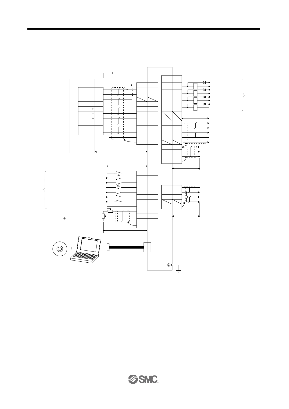
3. SIGNALS AND WIRING
(Note 12)
Plate
Plate
Servo amplifier
3
1
2
(Note 7)
CN6
(Note 2)
Trouble (Note 6)
Zero speed detection
Limiting torque
Encoder A-phase pulse
(differential line driver)
21
DICOM
48 ALM
23 ZSP
25 TLC
24 INP
4 LA
5 LAR
6 LB
7 LBR
34 LG
33 OP
1 P15R
SD
10m max.
2m max.
Encoder B-phase pulse
(differential line driver)
Control common
Encoder Z-phase pulse
(open collector)
(Note 7)
CN1
LG
DICOM
10m max. (Note 8)
41
20
46
49
10
11
35
9
3
36
CLEARCOM
12
15
16
14
13
11
CLEAR
RDYCOM
READY
PULSE F
PULSE F
PG0
PG0 COM
PULSE R
PULSE R
18
10
17
9
DOCOM
CR
RD
PP
PG
NP
NG
LZ
LZR
8
(Note 11)
(Note 7)
CN1
QD75D
Positioning module
24VDC
In-position
(Note 4, 12)
Control common
SD
RA1
RA2
RA3
RA4
Plate
(Note 1)
2m max.
10m max.
Upper limit setting
42
15
19
17
18
43
44
47
1
27
SD
EMG
SON
RES
PC
TL
LSP
LSN
DOCOM
P15R
TLA
LG 28
(Note 7)
CN1
Emergency stop
Servo-on
Reset
Proportion control
External torque limit selection
Forward rotation stroke end
Reverse rotation stroke end
(Note 3, 5)
(Note 5)
(Note 10)
USB cable
(option)
(Note 9)
MR Configurator
CN5
Analog torque limit
10V/max. torque
Personal
computer
(Note 12)
Plate
MO1
LG
MO2
SD
2m max.
Analog monitor 1
Analog monitor 2
Driver
(Note 9)
LEC-MR-J3USB
(option)
(Note 13)
(Note 13)
(Note 14)
(Note 14)
3.2 I/O signal connection example
3.2.1 Position control mode
Set up software
(MR Configurator2
TM
)
3 - 6

3. SIGNALS AND WIRING
MR-PRU03
parameter unit
CN3
EIA568-compliant cable (10BASE-T cable, etc.)
RS-232C/RS-422 conversion cable
Recommended product: Interface cable
DSV-CABV
(Diatrend)
Personal computer
Servo amplifier
or
To RS-232C connector
Driver
Mitsubishi Electric Corporation)
Note 1. To prevent an electric shock, always connect the protective earth (PE) terminal (terminal marked ) of the driver to the
protective earth (PE) of the control box.
2. Connect the diode in the correct direction. If it is connected reversely, the driver will be faulty and will not output signals,
disabling the emergency stop (EMG) and other protective circuits.
3. The emergency stop switch (normally closed contact) must be installed.
4. Supply 24VDC 10 300mA current for interfaces from the outside. 300mA is the value applicabl e when all I/O signals are
used. The current capacity can be decreased by reducing the number of I/O points. Refer to section 3.8.2 (1) that gives the
current value necessary for the interface.
5. When starting operation, always turn on emergency stop (EMG) and Forward/Reverse rotation stroke end (LSP/LSN).
(Normally closed contacts)
6. Trouble (ALM) turns on in normal alarm-free condition. When this signal is switched off (at occurrence of an alarm), the output
of the PC or PLC…etc should be stopped by the sequence program.
7. The pins with the same signal name are connected in the driver.
8. This length applies to the command pulse train input in the differential line driver system. It is 2m or less in the open collector
system.
9. Use LEC-MRC2E.
10. Personal computers or parameter units can also be connected via the CN3 connector, enabling RS-422 communication. Note
that using the USB communication function (CN5 connector) prevents the RS-422 communication function (CN3 connector)
from being used, and vice versa. They cannot be used together.
(
11. This connection is not required for the QD75D. Depending on the used positioning module, however, it is recommended to
connect the LG and control common terminals of the driver to enhance noise immunity.
12. For the sink I/O interface. For the source I/O interface, refer to section 3.8 .3.
13. If the command pulse train input is open collector method, it supports only to the sink (NPN) type interface.
It does not correspond to the source (PNP) type interface.
14. Encoder Z-phase pulse will correspond to the differential line driver system and the open collector system.
If the encoder Z-phase pulse is open collector method, it supports only to the sink (NPN) type interface. It does not correspond
to the source (PNP) type interface.
3 - 7

3. SIGNALS AND WIRING
3
1
2
(Note 7)
CN6
Plate
MO1
LG
MO2
SD
2m max.
Analog monitor 1
Analog monitor 2
(Note 10)
USB cable
(option)
(Note 9)
MR Configurator
Personal
computer
Upper limit setting
Emergency stop
Servo-on
Reset
Speed selection 1
Speed selection 2
Forward rotation stroke end
Reverse rotation stroke end
(Note 3, 5)
(Note 5)
Analog speed command
10V/rated speed
(Note 12)
Upper limit setting
Analog torque limit
10V/max. torque
(Note 11)
(Note 8)
Forward rotation start
Reverse rotation start
Encoder A-phase pulse
(differential line driver)
Encoder B-phase pulse
(differential line driver)
Control common
Encoder Z-phase pulse
(open collector)
Encoder Z-phase pulse
(differential line driver)
(Note 12)
Trouble (Note 6)
Zero speed detection
Limiting torque
Ready
Speed reached
Servo amplifier
(Note 1)
(Note 2)
21
DICOM
48 ALM
23 ZSP
25 TLC
24 SA
(Note 7)
CN1
49 RD
4 LA
5 LAR
6 LB
7 LBR
34 LG
33 OP
1 P15R
SD
10m max.
2m max.
8 LZ
9 LZR
(Note 7)
CN1
20
46
DICOM
DOCOM
2
1
2m max.
28
27
VC
SD
TLA
LG
P15R
CN5
24VDC
RA1
RA2
RA3
RA4
RA5
(Note 4)
10m max.
42
15
19
17
18
43
44
47
41
16
EMG
SON
RES
ST1
ST2
LSP
LSN
DOCOM
SP1
SP2
Plate
Plate
Driver
(Note 9)
LEC-MR-J3USB
(option)
(Note 13)
(Note 13)
3.2.2 Speed control mode
Set up software
(MR Configurator2
TM)
3 - 8

3. SIGNALS AND WIRING
MR-PRU03
parameter unit
CN3
EIA568-compliant cable (10BASE-T cable, etc.)
RS-232C/RS-422 conversion cable
Recommended product: Interface cable
DSV-CABV
(Diatrend)
Personal computer
Servo amplifier
or
To RS-232C connector
Driver
Mitsubishi Electric Corporation)
Note 1. To prevent an electric shock, always connect the protective earth (PE) terminal (terminal marked ) of the driver to the
protective earth (PE) of the control box.
2. Connect the diode in the correct direction. If it is connected reversely, the driver will be faulty and will not output signals,
disabling the emergency stop (EMG) and other protective circuits.
3. The emergency stop switch (normally closed contact) must be installed.
4. Supply 24VDC 10 300mA current for interfaces from the outside. 300mA is the value applic abl e when all I/O signals are
used. The current capacity can be decreased by reducing the number of I/O points. Refer to section 3.8.2 (1) that gives the
current value necessary for the interface.
5. When starting operation, always turn on emergency stop (EMG) and forward/reverse rotation stroke end (LSP/LSN). (Normally
closed contacts)
6. Trouble (ALM) turns on in normal alarm-free condition.
7. The pins with the same signal name are connected in the driver.
8. By setting parameters No.PD03 to PD08, PD09 to PD12 to make external torque limit selection (TL) available, TLA can be
used.
9. Use LEC-MRC2E.
10. Personal computers or parameter units can also be connected via the CN3 connector, enabling RS-422 communication. Note
that using the USB communication function (CN5 connector) prevents the RS-422 communication function (CN3 connector)
from being used, and vice versa. They cannot be used together.
(
11. Use an external power supply when inputting a negative voltage.
12. For the sink I/O int erface. For the source I/O interface, refer to section 3.8.3.
13. Encoder Z-phase pulse will correspond to the differential line driver system and the open collector system.
If the encoder Z-phase pulse is open collector method, it supports only to the sink (NPN) type interface. It does not correspond
to the source (PNP) type interface.
3 - 9

3. SIGNALS AND WIRING
3
1
2
(Note 6)
CN6
Plate
MO1
LG
MO2
SD
2m max.
Analog monitor 1
Analog monitor 2
Encoder A-phase pulse
(differential line driver)
Encoder B-phase pulse
(differential line driver)
Control common
Encoder Z-phase pulse
(open collector)
Encoder Z-phase pulse
(differential line driver)
(Note 10)
Trouble (Note 5)
Zero speed detection
Ready
Limiting speed
(Note 8)
USB cable
(option)
Upper limit setting
Emergency stop
Servo-on
Reset
Speed selection 1
Speed selection 2
(Note 3)
Analog torque command
8V/max. torque
(Note 10)
Upper limit setting
Analog speed limit
0 to 10V/rated speed
(Note 9)
Forward rotation selection
Reverse rotation selection
24VDC(Note 4)
Servo amplifier
(Note 1)
9
(Note 2)
21
DICOM
48 ALM
23 ZSP
25 VLC
4 LA
5 LAR
6 LB
7 LBR
34 LG
33 OP
1 P15R
SD
10m max.
2m max.
(Note 6)
CN1
49 RD
8 LZ
LZR
(Note 6)
CN1
20
46
DICOM
DOCOM
Personal
computer
CN5
27
1
2m max.
28
2
Plate
TC
SD
VLA
LG
P15R
(Note 7)
MR Configurator
Plate
10m max.
42
15
19
17
18
47
41
16
EMG
SON
RES
RS1
RS2
DOCOM
SP1
SP2
RA1
RA2
RA3
RA4
Driver
(Note 7)
LEC-MR-J3USB
(option)
(Note 11)
(Note 11)
3.2.3 Torque control mode
Set up software
(MR Configurator2
TM
)
3 - 10

3. SIGNALS AND WIRING
MR-PRU03
parameter unit
CN3
EIA568-compliant cable (10BASE-T cable, etc.)
RS-232C/RS-422 conversion cable
Recommended product: Interface cable
DSV-CABV
(Diatrend)
Personal computer
Servo amplifier
or
To RS-232C connector
Driver
Note 1. To prevent an electric shock, always connect the protective earth (PE) terminal of the (terminal marked ) driver to the
protective earth (PE) of the control box.
2. Connect the diode in the correct direction. If it is connected reversely, the driver will be faulty and will not output signals,
disabling the emergency stop (EMG) and other protective circuits.
3. The emergency stop switch(normally closed contact) must be installed.
4. Supply 24VDC 10 300mA current for interfaces from the outside. 300mA is the value applicabl e when all I/O signals are
used. The current capacity can be decreased by reducing the number of I/O points. Refer to section 3.8.2 (1) that gives the
current value necessary for the interface.
5. Trouble (ALM) turns on in normal alarm-free condition.
6. The pins with the same signal name are connected in the driver.
7. Use LEC-MRC2E.
8. Personal computers or parameter units can also be connected via the CN3 connector, enabling RS-422 communic ation. Note
that using the USB communication function (CN5 connector) prevents the RS-422 communication function (CN3 connector)
from being used, and vice versa. They cannot be used together.
9. Use an external power supply when inputting a negative voltage.
10. For the sink I/O interface. For the source I/O interface, refer to section 3.8.3.
11. Encoder Z-phase pulse will correspond to the differential line driver system and the open collector system.
If the encoder Z-phase pulse is open collector method, it supports only to the sink (NPN) type interface. It does not correspond
to the source (PNP) type interface.
3 - 11

3. SIGNALS AND WIRING
POINT
(application)
LECSB2-S8
LECSB1-S8
50/60Hz
50/60Hz
50/60Hz
Refer to section 12.13.
Refer to section 12.2 to 12.5.
Power supply
50/60Hz
50/60Hz
3.3 Explanation of power supply system
3.3.1 Signal explanations
For the layout of connector and terminal block, refer to outline drawings in
chapter 10.
Abbreviation
Connection target
Description
L1
L
L
P1
P
P
C
D
L11
L
2
3
Main circuit power
supply
Power factor improving
2
DC reactor
Regenerative option
Control circuit power
21
supply
Supply the following power to L
connect the power supply to L
Power supply
3-phase 200 to 230VAC,
1-phase 200 to 230VAC,
1-phase 100 to 120VAC,
When not using the power factor improving DC reactor, connect P
wired.)
When using the power factor improving DC reactor, disconnect P
power factor improving DC reactor to P
When using driver built-in regenerative resistor, connect P(
When using regenerative option, disconnect P(
to P and C.
Supply the following power to L
1-phase 200 to 230VAC,
1, L2, L3. For the 1-phase 200 to 230VAC power supply,
1, L2, and keep L3 open.
Driver
Driver
11 L21.
LECSB2-S5
LECSB2-S7
LECSB2-S8
L11 L21
LECSB2-S5
LECSB2-S7
L
1 and P2.
1・L2・L3
L1・L2
L1 L2
) and D, and connect regenerative option
LECSB1-S5
LECSB1-S7
LECSB1-S8
LECSB1-S5
LECSB1-S7
1 and P2. (Factory-
1 and P2, and connect the
) and D. (Factory-wired)
1-phase 100 to 120VAC,
3 - 12
L11 L21

3. SIGNALS AND WIRING
(application)
W
Brake unit
For details, refer to section 12.3 to 12.5.
(PE)
box to perform grounding.
95ms
95ms
Ready(RD)
Reset(RES)
Servo-on(SON)
OFF
ON
OFF
ON
ON
OFF
Base circuit
OFF
ON
OFF
ON
10ms5ms
10ms
10ms5ms
10ms
5ms 10ms
(1.5 to 2s)
Servo-on (SON) accepted
Main circuit
Control circuit
Power supply
Yes (OFF)
No (ON)
Trouble(ALM)
1s
(1 to 1.5s)
Abbreviation
Connection target
Description
U
V
N
Servo motor
power
Return converter
Protective earth
3.3.2 Power-on sequence (1) Power-on procedure
1) Always wire the power supply as shown in above section 3.1 using the magnetic contactor with the
main circui t powe r sup ply (3-phase: L
to switch off the magnetic contactor as soon as an alarm occurs.
2) Switch on th e co nt rol ci rc u it powe r sup ply L11, L21 simultaneously with the main circuit power supply
or before swit chi ng on the main circuit power s up ply . If t he main circuit powe r sup ply i s no t on, the
display show s the c or res pon di ng war nin g . How eve r , by swit ching on the main circuit power s up ply ,
the warning disappears and the driver will operate properly .
3) The driver can accept the servo-on (SON) about 1 to 2s after the main circuit power supply is
switched on. Therefore, when SON is switched on simultaneously with the main circuit power supply,
the base circuit will switch on in about 1 to 2s, and the ready (RD) will switch on in further about 5ms,
making the driver ready to operate. (Refer to paragraph (2) of this section.)
4) When the reset (RES) is switched on, the base circuit is shut off and the servo motor shaft coasts.
(2) Timing chart
Connect to the servo motor power supply terminals (U, V, W). During power-on, do not open or
close the motor power line. Otherwise, a malfunction or faulty may occur.
Do not connect to driver.
Connect to the earth terminal of the servo motor and to the protective earth (PE) of the control
1
, L2, L3, 1-phase: L1, L2). Configure up an external sequence
Power-on timing chart
3 - 13

3. SIGNALS AND WIRING
DICOM
EMGEmergency stop
24VDC
(Note)
Servo amplifier
Driver
(3) Emergency stop
Provide an external emergency stop circuit to ensure that operation can be stopped
CAUTION
and power swit ch ed off i mme di at ely.
Make up a circuit that shuts off main circuit power as soon as EMG is turned off at an emergency stop.
When EMG is turned off, the dynamic brake is operated to bring the servo motor to a sudden stop. At this
time, the display shows the servo emergency stop warning (AL.E6).
During ordinary operation, do not use the external emergency stop (EMG) to alternate stop and run.
The driver life may be shortened.
Also, if the forward rotation start (ST1) and reverse rotation start (ST2) are on or a pulse train is input during
an emergency stop, the servo motor will rotate as soon as the warning is reset. During an emergency stop,
always shut off the run command.
Note. For the sink I/O interface. For the source I/O interface, refer to section 3.8.3.
3 - 14

3. SIGNALS AND WIRING
POINT
Refer to section 12.11 for the wire sizes used for wiring.
CNP2
CNP1
CNP3
Connector for CNP1
54928-0670(M
olex)
Connector for CNP2
54927-0520(Molex)
Connector for CNP3
5492
8-0370(Molex)
<Applicable cable example>
Cable finish OD: to 3.8mm
(
Note
)
Servo amplifier
Power supply connectors
Servo amplifier
8 to 9mm
Sheath
Core
Cable size
Ferrule type (Note 1)
[mm2]
AWG
For 1 cable
For 2 cable
1.25/1.5
16
AI 1,5-10 BK
AI-TWIN2 1,5-10 BK
2/2.5
14
AI 2,5-10 BU
Driver
Driver Power supply connectors
200VAC / Part No. K05A50230490 (Note)
Part No. K05A50230491 (Note)
Part No. K05A50230492 (Note)
3.3.3 CNP1, CNP2, CNP3 wiring method
Use the supplied driver power supply connectors for wiring of CNP1, CNP2 and CNP3.
(1) LECSB□-□
(a) Driver power supply connectors
100VAC / Part No. K05A50230496 (Note)
Note. MITSUBISHI ELECT R IC SYSTEM & SERVICE CO., LTD
Please purchase from distributor or distributor of Mitsubishi Electric Corporation.
(b) Termination of the cables
Solid wire: After the sheath has been stripped, the cable can be used as it is.
Twisted wire: Use the cable after stripping the sheath and twisting the core. At this time, take care to
avoid a short caused by the loose wires of the core and the adjacent pole. Do not solder
the core as it may cause a contact fault. Alternatively, a ferrule may be used to put the
wires together.
Note 1. Manufacturer: Phoenix Contact
2. Manufacturer: WAGO
Crimping tool (Note 2)
Variocrimp 4 206-204
3 - 15

3. SIGNALS AND WIRING
POINT
MXJ
54932
7.7
4.7
Approx. 3 4.9
10
20.6
3.46.5
Approx. 4.9
Approx. 7.7
Approx.3.4
(2) Insertion of cable into connectors
Insertion of cable into connectors are as follows.
It may be difficult for a cable to be inserted to the connector depending on wire
size or ferrule configuration. In this case, change the wire type or correct it in
order to prevent the end of ferrule fr om widening, an d then inser t it.
How to connect a cable to the driver power supply connector is shown below.
(a) When using the supplied cable connection lever
1) The driver is packed with the cable connection lever.
[Unit: mm]
3 - 16

3. SIGNALS AND WIRING
1) Attach the cable connection lever to the housing.
(Detachable)
2) Push the cable connection lever in the direction
of arrow.
3) Hold down the cable connection lever and insert
the cable in the direction of arrow.
4) Release the cable connection lever.
Cable connection lever
2) Cable connection procedure
3 - 17

3. SIGNALS AND WIRING
3
0.6
Approx.R0.3
Approx.22
Approx.R0.3
3 to 3.5
1) Insert the screwdriver into the square hole.
Insert it along the top of the square hole to insert it smoothly.
2) If inserted properly, the screwdri
ver is held.
3) With the screwdriver held, insert the cable in the direction
of arrow. (Insert the cable as far as it will go.)
4) Releasing the screwdriver connects the cable.
(b) Inserting the cable into the connector
1) Applicable flat-blade screwdriver dimensions
Always use the screwdriver shown here to do the work.
2) When using the flat-blade screwdriver - part 1
[Unit: mm]
3 - 18

3. SIGNALS AND WIRING
1) Insert the screwdriver into the
square window at top of the
connector.
2) Push the screwdriver in the
direction of arrow.
3) With the screwdriver pushed, insert the cable in the
direction of arrow. (Insert the cable as far as it will go.)
4) Releasing the screwdriver connects the cable.
3) When using the flat-blade screwdriver - part 2
3 - 19

3. SIGNALS AND WIRING
POINT
P
C
D
L
11
L
21
L
1
U
L
2
L
3
N
P
1
P
2
V
W
2
4
6
8
10
12
14
16
18
20
22
24
1
3
5
7
9
11
13
15
17
19
21
23
27
29
31
33
35
37
39
41
43
45
47
49
26
28
30
32
34
36
38
40
42
44
46
48
25 50
2
LG
1
MO2
3
MO1
CN6
CN1
CN5
CN6CN3CN1CN2
CN5 (USB connector)
Refer to section 12.8.
CN3 (RS-422 connector)
Refer to section 13.1.
The frames of the CN1 connectors is
connected to the PE (earth) terminal
in the amplifier.
The 3M make connector is shown.
When using any other connector,
refer to section 12.1.2.
4
MRR
2
LG 8
6
1
P5
5
10
3
MR
7
9
BAT
CN2
MDR
MD
driver.
The Sumitomo 3M Limited make connector is shown.
12.3
3.4 Connectors and signal arrangements
The pin configurations of the connectors are as viewed from the cable connector
wiring section.
Refer to (2) of this section for CN1 signal assignment.
(1) Signal arrangement
The driver front view shown is that of the LECSB□-S5、LECSB□-S7. Refer to chapter 10 Outline
Drawings for the appearances and connector layouts of the other drivers.
3 - 20

3. SIGNALS AND WIRING
(Note 2) I/O signals in control modes
No.
1 P15R
P15R
P15R
P15R
P15R
P15R 2 I
/VC
VC
VC/VLA
VLA
VLA/ 3 LG
LG
LG
LG
LG
LG 4 O LA
LA
LA
LA
LA
LA 5 O LAR
LAR
LAR
LAR
LAR
LAR 6 O LB
LB
LB
LB
LB
LB 7 O LBR
LBR
LBR
LBR
LBR
LBR 8 O LZ
LZ
LZ
LZ
LZ
LZ 9 O LZR
LZR
LZR
LZR
LZR
LZR 10 I PP
PP/ /PP 11 I PG
PG/ /PG 12 OPC
OPC/ /OPC 13
14
15 I SON
SON
SON
SON
SON
SON
PD03
16 I
/SP2
SP2
SP2/SP2
SP2
SP2/
PD04
17 I PC
PC/ST1
ST1
ST1/RS2
RS2
RS2/PC
PD05
18 I TL
TL/ST2
ST2
ST2/RS1
RS1
RS1/TL
PD06
19 I RES
RES
RES
RES
RES
RES
PD07
20 DICOM
DICOM
DICOM
DICOM
DICOM
DICOM
21 DICOM
DICOM
DICOM
DICOM
DICOM
DICOM
22 O INP
INP/SA
SA
SA/ /INP
PD13
23 O ZSP
ZSP
ZSP
ZSP
ZSP
ZSP
PD14
24 O INP
INP/SA
SA
SA/ /INP
PD15
25 O TLC
TLC
TLC
TLC/VLC
VLC
VLC/TLC
PD16
26
TLA
TLA
TLA/TC
28 LG
LG
LG
LG
LG
LG 29
30 LG
LG
LG
LG
LG
LG 31
32
33 O OP
OP
OP
OP
OP
OP 34 LG
LG
LG
LG
LG
LG 35 I NP
NP/ /NP 36 I NG
NG/ /NG 37
38
39
40
41 I CR
CR/SP1
SP1
SP1/SP1
SP1
SP1/CR
PD08
42 I EMG
EMG
EMG
EMG
EMG
EMG
(2) CN1 signal assignment
The signal assignment of connector changes with the control mode as indicated below.
For the pins which are given parameter No.s in the related parameter column, their signals can be changed
using those parameters.
Related
parameter
Pin No.
(Note 1)
I/O
P P/S S S/T T T/P
27 I TLA
(Note 3)
(Note 3)
(Note 3)
TC TC/TLA
3 - 21

3. SIGNALS AND WIRING
(Note 2) I/O signals in control modes
No.
43 I LSP
LSP
LSP
LSP/ /LSP
PD10
44 I LSN
LSN
LSN
LSN/
/LSN
PD11
45 I LOP
LOP
LOP
LOP
LOP
LOP
PD12
46
DOCOM
DOCOM
DOCOM
DOCOM
DOCOM
DOCOM
47
DOCOM
DOCOM
DOCOM
DOCOM
DOCOM
DOCOM
48 O ALM
ALM
ALM
ALM
ALM
ALM 49 O RD
RD
RD
RD
RD
RD
PD18
50
Abbreviation
Signal name
Abbreviation
Signal name
SON
Servo-on
TLC
Limiting torque
LSP
Forward rotation stroke end
VLC
Limiting speed
LSN
Reverse rotation stroke end
RD
Ready
CR
Clear
ZSP
Zero speed detection
SP1
Speed selection 1
INP
In-position
SP2
Speed selection 2
SA
Speed reached
PC
Proportion control
ALM
Trouble
ST1
Forward rotation start
WNG
Warning
ST2
Reverse rotation start
BWNG
Battery warning
TL
External torque limit selection
OP
Encoder Z-phase pulse (open collector)
RES
Reset
MBR
Electromagnetic brake interlock
EMG
Emergency stop
LZ
(differential line driver)
LOP
Control selection
LZR
VC
Analog speed command
LA
(differential line driver)
VLA
Analog speed limit
LAR
TLA
Analog torque limit
LB
TC
Analog torque command
LBR
RS1
Forward rotation selection
DICOM
Digital I/F power supply input
RS2
Reverse rotation selection
OPC
Open collector power input
PP
DOCOM
Digital I/F common
NP
P15R
15VDC power supply
PG
LG
Control common
NG
SD
Shield
Pin No.
Note 1. I: Input signal, O: Output signal
2. P: Position control mode, S: Speed control mode, T: Torque control mode, P/S: Position/speed control changeover mode,
S/T: Speed/torque control changeover mode, T/P: Torque/position control changeover mode
3. TLA can be used when TL is made usable by setting the parameter No.PD03 to PD08/PD10 to PD12.
(Note 1)
I/O
(3) Explanation of abbreviations
P P/S S S/T
T T/P
Related
parameter
Encoder Z-phase pulse
Encoder A-phase pulse
Encoder B-phase pulse
(differential line driver)
Forward/reverse rotation pulse train
3 - 22

3. SIGNALS AND WIRING
No.
mode
P S T
terminals connected) automatically in the driver.
operation.
(Refer to section 5.4.3.)
(Note) Input device
Operation
direction
direction
1 1
0 1
stroke end
LSN
CN1-44 1 0
0 0
No.PD01
Status
LSP
LSN
4
Automatic ON
8
Automatic ON
C
Automatic ON
Automatic ON
WNG, set the parameter No.PD13 to PD16/PD18 to make it usable.
3.5 Signal explanations For the I/O interfaces (symbols in I/O division column in the table), refer to section 3.8.2. In the control mode field of the table P : Position control mode, S: Speed control mode, T: Torque control mode
: Denotes that the signal may be used in the initial setting status.
: Denotes that the signal may be used by setting the corresponding parameter No.PD03 to PD08, PD10 to
PD12, PD13 to PD16, PD18.
The pin No.s in the connector pin No. column are those in the initial status.
(1) I/O devices
(a) Input devices
Control
Device Symbol
Connec-
tor pin
Functions/Applications
I/O
division
Servo-on SON CN1-15 Turn SO N on to power on the base circuit and make the driver ready
to operate (servo-on).
Turn it off to shut off the base circuit and coast the servo motor.
Set "
Reset RES CN1-19 Turn RES on for more than 50ms to reset the alarm.
Some alarms cannot be deactivated by the reset (RES). Refer to
section 9.1.
Turning RES on in an alarm-free status shuts off the base circuit.
The base circuit is not shut off when "
No.PD20.
This device is not designed to make a stop. Do not turn it ON during
Forward rotation
stroke end
Reverse rotation
LSP CN1-43 To start operation, turn LSP/LSN on. Turn it off to bring the motor t o
a sudden stop and make it servo-locked.
Set "
4" in parameter No.PD01 to switch this signal on (keep
1 " is set in parameter
1" in parameter No.PD20 to make a slow stop.
LSP LSN
CCW
CW
DI-1
DI-1
DI-1
Note. 0: off
Set parameter No.PD01 as indicated below to switch on the signals
(keep terminals connected) automatically in the driver.
Parameter
When LSP or LSN turns OFF, an external stroke limit warning (AL.
99) occurs, and Warning (WNG) turns OFF. However, when using
1: on
3 - 23
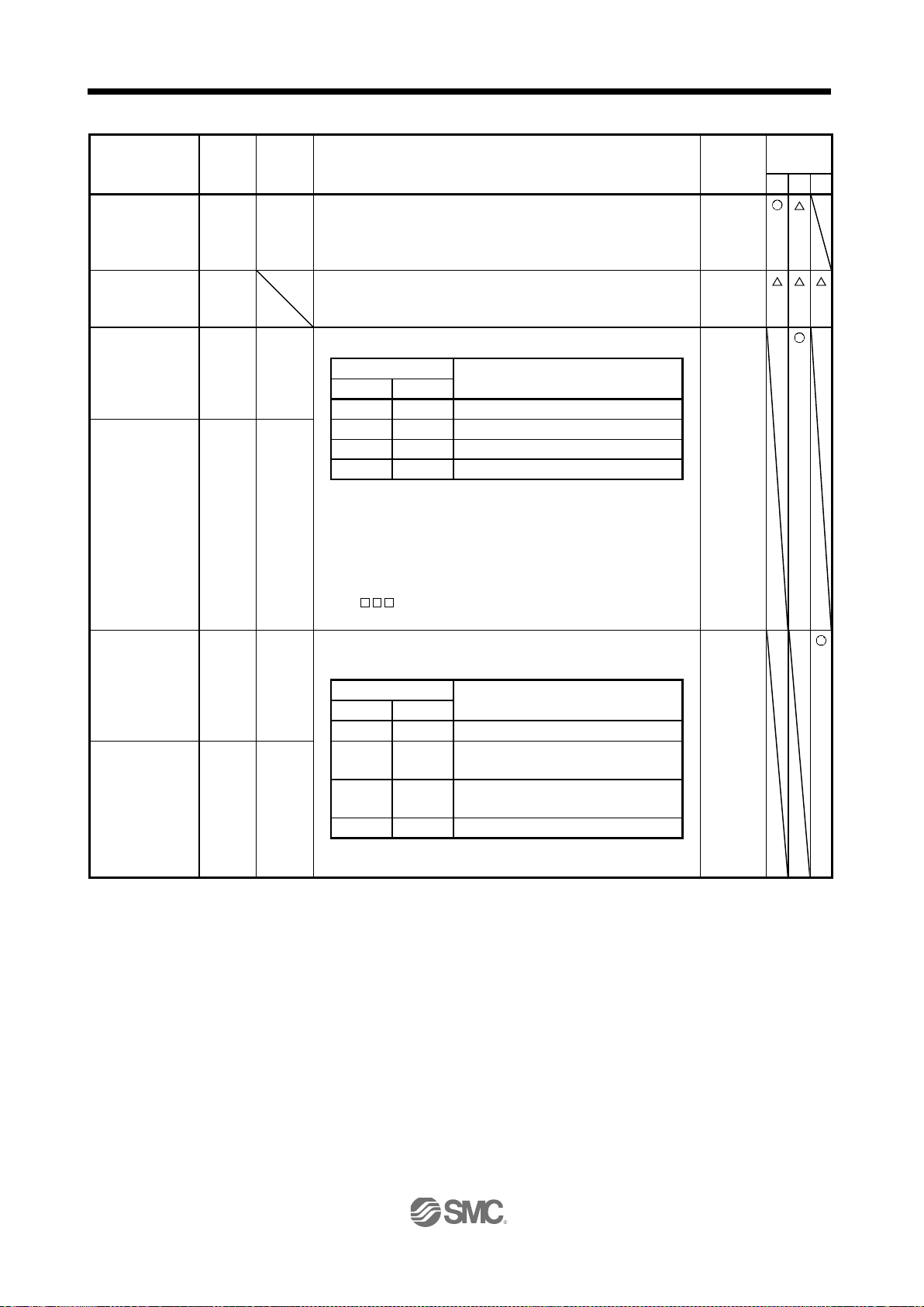
3. SIGNALS AND WIRING
No.
mode
P S T
For details, refer to section 3.6.1 (5).
For details, refer to section 3.6.1 (5).
(Note) Input device
ST2
ST1
0 0
Stop (servo lock)
start
ST2
CN1-18 0
1
CCW
1
0
CW
1 1
Stop (servo lock)
servo-locked after deceleration to a stop.
(Note) Input device
RS2
RS1
0 0
Torque is not generated.
selection
reverse rotation in regenerative mode
forward rotation in regenerative mode
1
1
Torque is not generated.
1: on
Device Symbol
Connec-
tor pin
Functions/Applications
I/O
division
Control
External torque
limit selection
Internal torque
limit selection
Forward rotation
start
Reverse rotation
Note. 0: off
Forward rotation
selection
TL CN1-18 Turn TL off to make Forward torque limit (parameter No.PA11) and
Reverse torque limit (parameter No.PA12) valid, or turn it on to
make Analog torque limit (TLA) valid.
TL1 When using this signal, make it usable by making the setting of
parameter No.PD03 to PD08, PD10 to PD12.
ST1 CN1-17 Used t o start the servo motor in any of the following directi ons.
1: on
If both ST1 and ST2 are switched on or off during operation, the
servo motor will be decelerated to a stop according to the parameter
No.PC02 setting and servo-locked.
When "
RS1 CN1-18 Used to select any of the following servo motor torque generation
directions.
DI-1
DI-1
DI-1
Servo motor starting direction
1" is set in parameter No.PC23, the servo motor is not
DI-1
Reverse rotation
Note. 0: off
RS2 CN1-17
0 1
1 0
Torque generation direction
Forward rotation in driving mode/
Reverse rotation in driving mode/
3 - 24

3. SIGNALS AND WIRING
No.
mode
P S T
Input device
SP3
SP2
SP1 0 0 0 Analog speed command (VC)
0 0 1
Internal sp eed c om ma nd 1 (par am et er No. PC 05)
0 1 0
Internal sp eed c om ma nd 2 (par am et er No.PC06)
Speed selection 3
SP3
0 1 1 Internal sp eed c om ma nd 3 (par am et er No. PC 07)
DI-1 1 0 0 Internal sp eed c om ma nd 4 (par am et er No. PC 08)
1 0 1 Internal sp eed c om ma nd 5 (par am et er No. PC 09)
1 1 0 Internal speed command 6 (para meter No.P C 1 0)
1 1 1 Internal sp eed c om ma nd 7 (par am et er No. PC 11)
Input device
SP3
SP2
SP1 0 0 0
Analog speed limit (VLA)
0 0 1 Internal speed limit 1 (parameter No.PC05)
0 1 0 Internal speed limit 2 (parameter No.PC06)
0 1 1 Internal speed limit 3 (parameter No.PC07)
1 0 0 Internal speed limit 4 (parameter No.PC08)
1 0 1 Internal speed limit 5 (parameter No.PC09)
1 1 0 Internal speed limit 6 (parameter No.PC10)
1 1 1 Internal speed limit 7 (parameter No.PC11)
1: on
Device Symbol
Connec-
tor pin
Functions/Applications
I/O
division
Control
Speed selection 1 SP1 CN1-41 <Speed control mode>
Used to select the command speed for operation.
When using SP3, make it usable by making the setting of parameter
No.PD03 to PD08, PD10 to PD12.
Speed selection 2 SP2 CN1-16
Note. 0: off
(Note)
1: on
<Torque control mode>
Used to select the limit speed for operation.
When using SP3, make it usable by making the setting of parameter
No.PD03 to PD08, PD10 to PD12.
Speed command
DI-1
DI-1
Note. 0: off
(Note)
Speed limit
3 - 25

3. SIGNALS AND WIRING
No.
mode
P S T
torque limit (TLA).
in the emergency stop state to reset that state.
cleared while CR is on.
CM2
(Note) Input device
DI-1
CM2
CM1
0 0 Parameter No.PA06
0 1 Parameter No.PC32
1 0 Parameter No.PC33
1 1 Parameter No.PC34
values into the parameter No.PB29 to PB34 values.
Device Symbol
Connec-
tor pin
Functions/Applications
I/O
division
Control
Proportion control PC CN1-17 Turn PC on to switch the speed amplifier from the proportional
integral type to the proportional type.
If the servo motor at a stop is rotated even one pulse due to any
external factor, it generates torque to compensate for a position
shift. When the servo motor shaft is to be locked mechanically after
positioning completion (stop), switching on the proportion control
(PC) upon positioning completion will suppress the unnecessary
torque generated to compensate for a position shift.
When the shaft is to be locked for a long time, switch on the
proportion control (PC) and external torque limit selection (TL) at the
same time to make the torque less than the rated by the analog
Emergency stop EMG CN1-42 Turn EMG off (open between commons) to bring the motor to an
emergency stop state, in which the base circuit is shut off and the
dynamic brake is operated. Turn EMG on (short between commons)
Clear CR CN1-41 Turn CR on to clear the position control counter droop pulses on its
leading edge. The pulse width should be 10ms or longer.
The delay amount set in parameter No.PB03 (position command
acceleration/deceleration time constant) is also cleared. When the
1 ", the pulses are always
Electronic gear
selection 1
parameter No.PD22 setting is "
CM1 When using CM1 and CM2, make them usable by the setting of
parameters No.PD03 to PD08, PD10 to PD12.
The combination of CM1 and CM2 gives you a choice of four
different electronic gear numerators set in the parameters.
CM1 and CM2 cannot be used in the absolute position detection
system.
DI-1
DI-1
DI-1
DI-1
Electronic gear
selection 2
Note. 0: off
Gain changing CDP W hen using this signal, make it usable by the setting of parameter
1: on
No.PD03 to PD08, PD10 to PD12.
Turn CDP on to change the load inertia moment ratio and gain
Electronic gear molecule
3 - 26
DI-1

3. SIGNALS AND WIRING
No.
mode
P S T
(Note) LOP
Control mode
0
Position
1 Speed
(Note) LOP
Control mode
0 Speed
1 Torque
(Note) LOP
Control mode
0 Torque
1 Position
1: on
(Note) STAB2
Acceleration/deceleration time constant
Acceleration time constant
(parameter No.PC02)
Acceleration time constant 2
(parameter No.PC31)
1: on
transfer. (Refer to chapter 14.)
transfer. (Refer to chapter 14.)
Device Symbol
Connec-
tor pin
Functions/Applications
I/O
division
Control
Control change LOP CN1-45 <Position/speed control change mode>
Used to select the control mode in the position/speed control change
mode.
Note. 0: off
1: on
<Speed/torque control change mode>
Used to select the control mode in the speed/torque control change
mode.
Note. 0: off
1: on
<Torque/position control mode>
Used to select the control mode in the torque/position control
change mode.
DI-1 Refer to
Functions/
Appli-
cations.
Note. 0: off
Second
acceleration/dece
leration selection
Note. 0: off
ABS transfer
mode
ABS request ABSR CN1-18 ABS request device.
STAB2
ABSM CN1-17 ABS transfer mode request device.
When using this signal, set the parameter No.PD03 to PD08/PD10
to PD12 to make it usable.
This signal allows selection of the acceleration/deceleration time
constant at servo motor rotation in the speed control mode or torque
control mode. The S-pattern acceleration/deceleration time constant
is always uniform.
0
1
The CN1-17 pin acts as ABSM only during absolute position data
The CN1-18 pin acts as ABSR only during absolute position data
DI-1
(parameter No.PC01)
Deceleration time constant
(parameter No.PC30)
Deceleration time constant 2
DI-1
DI-1
3 - 27

3. SIGNALS AND WIRING
No.
mode
P S T
turns on within 1s after power-on.
For the driver of 7kW or less, it is not necessary to use this device.
operate.
INP turns on when servo on turns on.
reverse rotation start (ST2) are off.
when servo on (SON) turns off.
(parameter No.PA12) or analog torque limit (TLA).
(b) Output devices
Device Symbol
Connec-
tor pin
Functions/Applications
I/O
division
Control
Trouble ALM CN1-48 ALM turns off when power is switched off or the protective circuit is
activated to shut off the base circuit. Without alarm occurring, ALM
Dynamic brake
interlock
Ready RD CN1-49 RD turns on when the servo is switched on and the driver is ready to
In-position INP CN1-24 INP turns on when the number of droop pulses is in the preset in-
Speed reached SA SA turns on when the servo motor speed has nearly reached the
Limiting speed VLC CN1-25 VLC turns on when speed reaches the value limited using any of the
DB When using the signal, make it usable by the setting of parameter
No.PD13 to PD16 and PD18.
DB turns off when the dynamic brake needs to operate. When using
the external dynamic brake on the driver of 11 kW or more, this
device is required. (Refer to section 12.6)
position range. The in-position range can be changed using
parameter No.PA10.
When the in-position range is increased, may be kept connected
during low-speed rotation.
preset speed. When the preset speed is 20r/min or less, SA always
turns on. SA does not turn on even when the servo on (SON) is
turned off or the servo motor speed by the external force reaches
the preset speed while both the forward rotation start (ST1) and the
internal speed limits 1 to 7 (parameter No.PC05 to PC11) or the
analog speed limit (VLA) in the torque control mode. VLC turns off
DO-1
DO-1
DO-1
DO-1
DO-1
DO-1
Limiting torque TLC TLC turns on when the torque generated reaches the value set to
the Forward torque limit (parameter No.PA11), Reverse torque limit
DO-1
3 - 28

3. SIGNALS AND WIRING
No.
mode
P S T
OFF
ON
0r/min
1)
2)
4)
Forward
rotation
direction
Servo motor
speed
Reverse
rotation
direction
Zero speed
detection
(ZSP)
ON level
50r/min
OFF level
70r/min
ON level
50r/min
OFF level
70r/min
Parameter
No. PC17
20r/min
(Hysteresis width)
20r/min
(Hysteresis width)
Parameter
No. PC17
3)
Hysteresis width is 20r/min for the LECSB□-□ driver.
MBR turns off when the servo is switched off or an alarm occurs.
warning, WNG turns off within about 1.5s after power-on.
after power-on.
Device Symbol
Connec-
tor pin
Functions/Applications
I/O
division
Control
Zero speed
detection
ZSP CN1-23 ZSP turns on when the servo motor speed is zero speed (50r/min)
or less. Zero speed can be changed using parameter No.PC17.
Example
Zero speed is 50r/min
ZSP turns on 1) when the servo motor is decelerated to 50r/min, and
ZSP turns off 2) when the servo motor is accelerated to 70r/min
again.
ZSP turns on 3) when the servo motor is decelerated again to
50r/min, and turns off 4) when the servo motor speed has reached 70r/min.
The range from the point when the servo motor speed has reached
ON level, and ZSP turns on, to the point when it is accelerated again
and has reached OFF level is called hysteresis width.
DO-1
Electromagnetic
brake interlock
MBR Set the parameter No.PD13 to PD16/PD18 or parameter No.PA04
to make this signal usable. Note that ZSP will be unusable.
Warning WNG To use this signal, assign the connector pin for output using
parameter No.PD13 to PD16, PD18. The old signal before
assignment will be unusable.
When warning has occurred, WNG turns on. When there is no
Battery warning BWNG T o use this signal, assign the connector pin for output using
parameter No.PD13 to PD16, PD18. The old signal before
assignment will be unusable.
BWNG turns on when battery cable disconnection warning (AL. 92)
or battery warning (AL. 9F) has occurred.
When there is no battery warning, BWNG turns off within about 1.5s
DO-1
DO-1
DO-1
3 - 29

3. SIGNALS AND WIRING
No.
mode
P S T
Alarm code
ACD 0
CN1-24
DO-1
ACD 1
CN1-23
(Note) Alarm code
22
23
24
88888
Watchdog AL.12
Memory error 1
AL.13
Clock error
AL.15
Memory error 2
AL.17
Board error
AL.19
Memory error 3
AL.37
Parameter error
time-out error
AL.8E
Serial communication error
AL.30
Regenerative error
AL.33
Overvoltage
0 1 0 AL.10
Undervoltage
overheat
AL.46
Servo motor overheat
AL.47
Cooling fan alarm
AL.50
Overload 1
AL.51
Overload 2
AL.24
Main circuit error
AL.32
Overcurrent
AL.31
Overspeed
frequency alarm
AL.52
Error excessive
AL.16
Encoder error 1
AL.1A
Monitor combination error
AL.20
Encoder error 2
AL.25
Absolute position erase
1: on
selection
erasing
data bit 0
during ABS transmission data transmission. (Refer to chapter 14.)
data bit 1
during ABS transmission data transmission. (Refer to chapter 14.)
data ready
during ABS transmission data transmission. (Refer to chapter 14.)
Connec-
Signal Symbol
ACD 2 CN1-22
tor pin
To use this signal, set " 1" in parameter No.PD24.
This signal is output when an alarm occurs. When there is no alarm,
respective ordinary signals (RD, INP, SA, ZSP) are output.
Alarm codes and alarm names are listed below.
Functions/Applications
I/O
division
Control
CN1-
0 0 0
0 0 1
0 1 1
1 0 0
CN1-
CN1-
Alarm
display
AL.8A
AL.45
Name
Serial communication
Main circuit device
Note. 0: off
Variable gain
Absolute position
ABS transmission
ABS transmission
ABS transmission
CDPS CDPS is on during gain changing. DO-1
ABSV ABSV turns on when the absolute position is erased. DO-1
ABSB0 CN1-22 Outputs ABS transmission data bit 0. CN1-22 acts as ABSB0 only
ABSB1 CN1-23 Outputs ABS transmission data bit 1. CN1-23 acts as ABSB1 only
ABST CN1-25 Outputs ABS transmission data ready. CN1-25 acts as ABST only
1 0 1 AL.35
1 1 0
3 - 30
Command pulse
DO-1
DO-1
DO-1

3. SIGNALS AND WIRING
No.
mode
P S T
Resolution:10bit
The torque at 8V input can be changed using parameter No.PC13.
Resolution:14bit or equivalent
limit
No.PC12 is provided at 10V. (Refer to section 3.6.3 (3).)
input
PA13.
(2) Input signals
Signal Symbol
Connec-
tor pin
Functions/Applications
I/O
division
Control
Analog torque
limit
Analog torque
command
Analog speed
command
Analog speed
Forward rotation
pulse train
Reverse rotation
pulse train
TLA CN1-27 To use this signal in the speed control mode, set any of parameters
No.PD13 to PD16, PD18 to make external torque limit selection (TL)
available.
When the analog torque limit (TLA) is valid, torque is limited in the
full servo motor output torque range. Apply 0 to
TLA-LG. Connect the positive terminal of the power supply to TLA.
Maximum torque is generated at
TC Used to control torque in the full servo motor output torque range.
Apply 0 to
8V. (Refer to section 3.6.3 (1).)
VC CN1-2 Apply 0 to 10VDC across VC-LG. Speed set in parameter
No.PC12 is provided at
VLA Apply 0 to 10VDC across VLA-LG. Speed set in parameter
PP
NP
PG
NG
CN1-10
CN1-35
CN1-11
CN1-36
Used to enter a command pulse train.
In the open collector system (max. input frequency 200kpps)
Forward rotation pulse train across PP-DOCOM
Reverse rotation pulse train across NP-DOCOM
If the command pulse train input is open collector method, it supports
only to the sink (NPN) type interface.
It does not correspond to the source (PNP) type interface.
In the differential receiver system (max. input frequency 1Mpps)
Forward rotation pulse train across PG-PP
Reverse rotation pulse train across NG-NP
The command pulse train form can be changed using parameter No.
8VDC across TC-LG. Maximum torque is generated at
10V. (Refer to section 3.6.1 (5).)
10V. (Refer to section 3.6.2 (1).)
10VDC across
Analog
input
Analog
input
Analog
input
Analog
DI-2
3 - 31

3. SIGNALS AND WIRING
No.
mode
P S T
using this pulse, set the creep speed to 100r/min. or less.
driver)
driver)
driver)
LG in terms of voltage. Resolution: 10 bits or equivalent
output
LG in terms of voltage. Resolution: 10 bits or equivalent
output
POINT
No.
mode
P S T
RDN
CN3-6
(3) Output signals
Signal Symbol
Connec-
tor pin
Functions/Applications
I/O
division
Control
Encoder Z-phase
pulse
(Open collector)
Encoder A-phase
pulse
(Differential line
Encoder B-phase
pulse
(Differential line
Encoder Z-phase
pulse
(Differential line
Analog monitor 1 MO1 CN6-3 Used to output the data set in parameter No.PC14 to across MO1-
Analog monitor 2 MO2 CN6-2 Used to output the data set in parameter No.PC15 to across MO2-
OP CN1-33 Outputs the zero-point signal of the encoder. One pulse is output per
servo motor revolution. OP turns on when the zero-point position is
reached. (Negative logic)
s. For home position return
LA
LAR
LB
LBR
LZ
LZR
CN1-4
CN1-5
CN1-6
CN1-7
CN1-8
CN1-9
The minimum pulse width is about 400
Outputs pulses per servo motor revolution set in parameter No.PA15
in the differential line driver system. In CCW rotation of the servo
motor, the encoder B-phase pulse lags the encoder A-phase pulse
by a phase angle of
The relationships between rotation direction and phase difference of
the A- and B-phase pulses can be changed using parameter No.
PC19.
The same signal as OP is output in the differential line driver
system.
/2.
(4) Communication
DO-2
DO-2
DO-2
Analog
Analog
Signal Symbol
RS-422 I/F SDP
SDN
RDP
Refer to chapter 13 for the communication function.
Connec-
tor pin
CN3-5
CN3-4
CN3-3
Terminals for RS-422 communication. (Refer to chapter 13.)
Functions/Applications
I/O
division
Control
3 - 32

3. SIGNALS AND WIRING
No.
mode
P S T
connect of 24VDC external power supply.
power input
terminal with the positive ( ) power of 24VDC.
24VDC external power supply.
Permissible current: 30mA
CN6-1
Shield
SD
Plate
Connect the external conductor of the shield cable.
(5) Power supply
Signal Symbol
Connec-
tor pin
Functions/Applications
I/O
division
Control
Digital I/F power
supply input
Open collector
Digital I/F
common
15VDC power
supply
Control common LG CN1-3
DICOM CN1-20
CN1-21
OPC CN1-12 When inputting a pulse train in the open collector system, supply this
DOCOM CN1-46
CN1-47
P15R CN1-1 Outputs 15V DC to across P15R-LG. Available as power for TC,
CN1-28
CN1-30
CN1-34
CN3-1
CN3-7
Used to input 24VDC (24VDC 10 300mA) for I/O interface of the
driver. The power supply capacity changes depending on the
number of I/O interface points to be used. For sink interface,
connect
Common terminal for input device such as SON and EMG of the
driver. Pins are connected internally. For sink interface, connect
of 24VDC external power supply. For source interface, connect
TLA, VC, VLA.
Common terminal for TLA, TC, VC, VLA, FPA, FPB, OP ,MO1, MO2
and P15R.
Pins are connected internally.
of 24VDC external power supply. For source interface,
of
3 - 33

3. SIGNALS AND WIRING
SD
Servo amplifier
OPC
PP
NP
DOCOM
24VDC
(Note)
Approx.
1.2k
Approx.
1.2k
(ON)(OFF)
(ON) (OFF) (ON) (OFF) (ON)
(OFF)
Forward rotation
pulse train
(transistor)
Reverse rotation
pulse train
(transistor)
(ON)(OFF)
Forward rotation command
Reverse rotation command
(OFF)
Driver
3.6 Detailed description of the signals
3.6.1 Position control mode (1) Pulse train input
(a) Input pulse waveform selection
Command pulses may be input in any of three different forms, for which positive or negative logic can
be chosen. Set the command pulse train form in parameter No.PA13. Refer to section 5.1.10 for details.
(b) Connections and waveforms
1) Open collector system
Connect as shown below.
Note. Pulse train input interface is comprised of a photo coupler.
Therefore, it may be any malfunctions since the current is reduced when connect a
resistance to a pulse train signal line.
If the command pulse train input is open collector method, it supports only to the sink
(NPN) type interface.
It does not correspond to the source (PNP) type interface.
The explanation assumes that the input waveform has been set to the negative logic and forward and
reverse rotation pulse trains (parameter No.PA13 has been set to 0010). Their relationships with
transistor ON/OFF are as follows.
3 - 34

3. SIGNALS AND WIRING
Approx.
100
PP
NP
Servo amplifier
PG
N
G
SD
(Note)
Approx.
100
PP
PG
NP
NG
Forward rotation
pulse train
Reverse rotation
pulse train
Forward rotation command Reverse rotation command
Servo-on (SON)
Alarm
Droop pulses
ON
OFF
Yes
No
In-position range
ON
OFF
In-position (INP)
Driver
2) Differential line driver system
Connect as shown below.
Note. Pulse train input interface is comprised of a photo coupler.
Therefore, it may be any malfunctions since the current is reduced when connect a
resistance to a pulse train signal line.
The explanation assumes that the input waveform has been set to the negative logic and forward and
reverse rotation pulse trains (parameter No.PA13 has been set to 0010).
The waveforms of PP, PG, NP and NG are based on that of the LG of the differential line driver.
(2) In-position (INP)
INP turns on when the number of droop pulses in the deviation counter falls within the preset in-position
range (parameter No.PA10). INP turns on when low-speed operation is performed with a large value set as
the in-position range.
3 - 35

3. SIGNALS AND WIRING
Servo-on (SON)
Alarm
Ready (RD)
ON
OFF
Yes
No
100ms or less 10ms or less 10ms or less
ON
OFF
(Note) Input device
CM2
CM1
0
0
Parameter No.PA06
0
1
Parameter No.PC32
1
0
Parameter No.PC33
1
1
Parameter No.PC34
0 10010
0
[%]
CW direction
Max. torque CCW direction
Torque
Torque limit value in
parameter No.PA12
Torque limit value in
parameter No.PA11
(3) Ready (RD)
(4) Electronic gear switching
The combination of CM1 and CM2 gives you a choice of four different electronic gear numerators set in the
parameters.
As soon as CM1/CM2 is turned ON or OFF, the molecule of the electronic gear changes. Therefore, if any
shock occurs at this change, use position smoothing (parameter No.PB03) to relieve shock.
Electronic gear molecule
(5) Torque limit
CAUTION
(a) Torque limit and torque
By setting parameter No.PA11 (forward rotation torque limit) or parameter No.PA12 (reverse rotation
torque limit ), to rqu e is always limit e d to the maximum value during operation. A relationship between the
limit value and servo motor torque is shown below.
Note. 0: off
1: on
If the torque limit is canceled during servo lock, the servo motor may suddenly rotate
according to position deviation in respect to the command position.
3 - 36

3. SIGNALS AND WIRING
5
Connection example
Japan resistor
RRS10 or equivalent
TLA application voltage vs.
torque limit value
TLA application voltage [V]
000.05 10
(Note)
TL
DOCOM
P15R
TLA
LG
SD
2k
2k
Servo amplifier
Torque limit value [ ]
100
(Note) Input device
Validated torque limit values
CCW driving/CW
regeneration
CW driving/CCW
regeneration
0
0
Parameter No.PA11
Parameter No.PA12
Parameter No.PA11
Parameter No.PA12
Parameter No.PA11
Parameter No.PA12
Parameter No.PA11
Parameter No.PA12
Parameter No.PA11
Parameter No.PA12
TLA
Parameter No.PC35
Parameter No.PC35
Parameter No.PC35
TLA
Parameter No.PC35
TLA
TLA
Driver
A relationship between the applied voltage of the analog torque limit (TLA) and the torque limit value of
the servo moto r i s sh ow n bel ow . To rqu e limit values will vary about 5 relative to the voltage
depending on products.
At the voltage of less than 0.05V, torque may vary as it may not be limited sufficiently. Therefore, use
this function at the voltage of 0.05V or more.
(b) Torque limit value selection
As shown below, the forward rotation torque limit (parameter No.PA11), or reverse rotation torque limit
(parameter No. PA12) and the analog torque limit (TLA) can be chosen using the external torque limit
selection (TL).
When internal torque limit selection (TL1) is made usable by parameter No.PD03 to PD08, PD10 to
PD12, internal torque limit 2 (parameter No.PC35) can be selected. However, if the parameter No.PA11
and parameter No.PA12 value is less than the limit value selected by TL/TL1, the parameter No.PA11
and parameter No.PA12 value is made valid.
Note. For the sink I/O interface. For the source I/O interfac e, ref er to section 3.8. 3.
TL1 TL
0 1
1 0
1 1
Note. 0: off
1: on
(c) Limiting torque (TLC)
TLC turns on when the servo motor torque reaches the torque limited using the forward rotation torque
limit, reve r se rot at io n t o rque l i mit or analog torque limit.
Parameter No.PC35
Parameter No.PC35
Limit value status
TLA
TLA
Parameter No.PA11 Parameter No.PA12
TLA TLA
Parameter No.PA11 Parameter No.PA12
Parameter No.PC35 Paramet er No.PC35
3 - 37

3. SIGNALS AND WIRING
Forward rotation (CCW)
Reverse rotation (
CW
)
-
10
Rated speed [r/min]
CCW direction
0 +10
VC applied voltage [V]
CW direction
Rated speed
Speed [r/min]
(Note 1) Input device
(Note 2) Rotation direction
Analog speed command (VC)
commands
Polarity
0V
Polarity
(Servo lock)
(Servo lock)
(Servo lock)
(Servo lock)
0 1 CCW
(No servo lock)
CW
CCW
1 0 CW
CCW
CW
(Servo lock)
(Servo lock)
(Servo lock)
(Servo lock)
ST2
DOCOM
P15R
VC
LG
SD
ST1
Japan resistor
RRS10 or equivalent
(Note)
2k
2k
Servo amplifier
Driver
3.6.2 Speed control mode (1) Speed setting
(a) Speed command and speed
The servo motor is run at the speeds set in the parameters or at the speed set in the applied voltage of
the analog speed command (VC). A relationship between the analog speed command (VC) applied
voltage and the servo motor speed is shown below.
Rated speed is achieved at
parameter No.PC12.
10V with initial setting. The speed at 10V can be changed using
The following table indicates the rotation direction according to forward rotation start (ST1) and reverse
rotation start (ST2) combination.
ST2 ST1
0 0
1 1
Note 1. 0: off
1: on
2. If the torque limit is canceled during servo lock, the servo motor may suddenly rotate according to position deviation in respect
to the command position.
Stop
Stop
Stop
Stop
Stop
Stop
Stop
Internal speed
Generally, make connection as shown below.
Stop
Stop
Note. For the sink I/O interface. For the source I/O interface, refer to section 3.8.3.
3 - 38

3. SIGNALS AND WIRING
(Note) Input device
SP2
SP1 0 0
Analog speed command (VC)
0
1
Internal speed command 1 (parameter No.PC05)
1
0
Internal speed command 2 (parameter No.PC06)
1
1
Internal speed command 3 (parameter No.PC07)
(Note) Input device
SP3
SP2
SP1 0 0 0 Analog speed command (VC)
0 0 1
Internal speed command 1 (parameter No.PC05)
0 1 0
Internal speed command 2 (parameter No.PC06)
0 1 1
Internal speed command 3 (parameter No.PC07)
1 0 0
Internal speed command 4 (parameter No.PC08)
1 0 1
Internal speed command 5 (parameter No.PC09)
1 1 0
Internal speed command 6 (parameter No.PC10)
1 1 1
Internal speed command 7 (parameter No.PC11)
ON
OFF
ON
OFF
Set speed selection
Internal speed
command 1
Internal speed
command 2
Start (ST1,ST2)
Servo motor speed
Speed reached (SA)
(b) Speed selection 1 (SP1), speed selection 2 (SP2) and speed command value
Choose any of the speed settings made by the internal speed commands 1 to 3 using speed selection 1
(SP1) and speed selection 2 (SP2) or the speed setting made by the analog speed command (VC).
Speed command value
Note. 0: off
1: on
By making speed selection 3 (SP3) usable by setting of parameter No.PD03 to PD08/PD10 to PD12,
you can choose the speed command values of analog speed command (VC) and internal speed
commands 1 to 7.
Speed command value
(2) Speed reached (SA)
(3) Torque limit
Note. 0: off
1: on
The speed may be changed during rotation. In this case, the values set in parameters No.PC01 and
PC02 are used for acceleration/deceleration.
When the speed has been specified under any internal speed command, it does not vary due to the
ambient temperature.
SA turns on when the servo motor speed has nearly reached the speed set to the internal speed command
or analog speed command.
As in section 3.6.1 (5).
3 - 39

3. SIGNALS AND WIRING
Forward rotation (CCW)
Reverse rotation (CW)
-10
Rated speed [r/min]
CCW direction
0 +10
VC applied voltage [V]
CW direction
Rated speed
Speed[r/min]
(Note) Input device
Rotation direction
Torque control command (TC)
Polarity
0V
Polarity
0
0
Torque is not generated.
Torque is not generated.
in regenerative mode)
in regenerative mode)
in regenerative mode)
in regenerative mode)
1
1
Torque is not generated.
Torque is not generated.
RS2
DOCOM
TC
LG
SD
8 to
8V
Servo amplifier
RS1
(Note)
Driver
3.6.3 Torque control mode (1) Torque control
(a) Torque command and torque
A relationship between the applied voltage of the analog torque command (TC) and the torque by the
servo motor is shown below.
The maximum torque is generated at
parameter No.PC13.
Generated torque limit values will vary about 5 relative to the voltage depending on products.
Also the torque may vary if the voltage is low ( 0.05 to 0.05V) and the actual speed is close to the
limit value. In such a case, increase the speed limit value.
The following table indicates the torque generation directions determined by the forward rotation
selection (RS1) and reverse rotation selection (RS2) when the analog torque command (TC) is used.
8V. Note that the torque at 8V input can be changed with
RS2 RS1
0 1
1 0
Note. 0: off
1: on
CCW (reverse rotati on in
driving mode/forward rotation
CW (forward rotation in
driving mode/reverse rotation
Torque is not
generated.
CW (forward rotation in
driving mode/reverse rotation
CCW (reverse rotation in
driving mode/forward rotation
Generally, make connection as shown below.
Note. For the sink I/O interface. For the source I/O interface, refer to section 3.8.3.
3 - 40
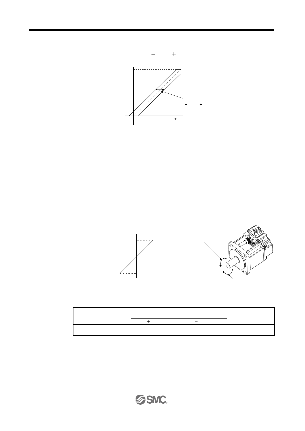
3. SIGNALS AND WIRING
0
8( 8)
Max. torque
Generated torque
TC applied voltage [V]
Parameter No. PC38 offset range
999 to 999mV
Forward rotation (CCW)
Reverse rotation (CW)
-10
Rated speed [r/min]
CCW direction
0
+10
VC applied voltage [V]
CW direction
Rated speed
Speed[r/min]
(Note) Input device
Speed limit direction
Analog speed limit (VLA)
Internal speed
commands
Polarity
Polarity
1 0 CCW
CW
CCW
0 1 CW
CCW
CW
(b) Analog torque command offset
Using parameter No.PC38, the offset voltage of
999 to 999mV can be added to the TC applied
voltage as show n bel ow .
(2) Torque limit
By setting parameter No.PA11 (forward rotation torque limit) or parameter No.PA12 (reverse rotation torque
limit), torque is always limited to the maximum value during operation. A relationship between limit value
and servo motor torque is as in section 3.6.1 (5). Note that the analog torque limit (TLA) is unavailable.
(3) Speed limit
(a) Speed limit value and speed
The speed is limited to the values set in parameters No.PC05 to PC11 (internal speed limits 1 to 7) or
the value set in t he app lie d vol ta ge of t he ana lo g sp eed li mi t ( VLA ) .
A relationship between the analog speed limit (VLA) applied voltage and the servo motor speed is
shown below.
When the servo motor speed reaches the speed limit value, torque control may become unstable. Make
the set value more than 100r/min greater than the desired speed limit value.
The following table indicates the limit direction according to forward rotation selection (RS1) and reverse
rotation selection (RS2) combination.
RS1 RS2
Note. 0: off
1: on
3 - 41
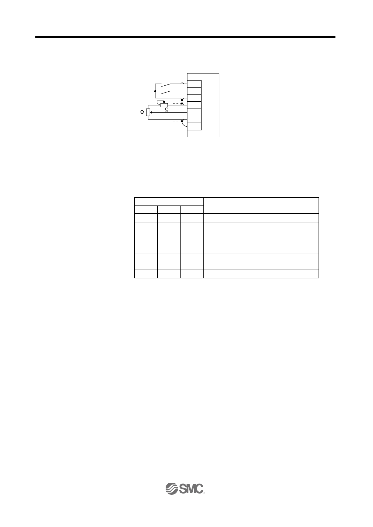
3. SIGNALS AND WIRING
SP2
DOCOM
P15R
VLA
LG
SD
SP1
Japan resistor
RRS10 or equivalent
(Note)
2k
2k
Servo amplifier
(Note) Input device
SP3
SP2
SP1 0 0 0 Analog speed limit (VLA)
0 0 1
Internal speed limit 1 (parameter No.PC05)
0 1 0
Internal speed limit 2 (parameter No.PC06)
0 1 1
Internal speed limit 3 (parameter No.PC07)
1 0 0
Internal speed limit 4 (parameter No.PC08)
1 0 1
Internal speed limit 5 (parameter No.PC09)
1 1 0
Internal speed limit 6 (parameter No.PC10)
1 1 1
Internal speed limit 7 (parameter No.PC11)
Driver
Generally, make connection as shown below.
Note. For the sink I/O interface. For the source I/O interface, refer to section 3.8.3.
(b) Speed selection 1(SP1)/speed selection 2(SP2)/speed selection 3(SP3) and speed limit values
Choose any of the speed settings made by the internal speed limits 1 to 7 using speed selection 1(SP1),
speed selection 2(SP2) and speed selection 3(SP3) or the speed setting made by the analog speed
limit (VLA) , a s indi c at ed bel ow .
Speed limit value
When the internal speed limits 1 to 7 are used to command the speed, the speed does not vary with the
ambient temperature.
(c) Limiting speed (VLC)
VLC turns on when the servo motor speed reaches the speed limited using any of the internal speed
limits 1 to 7 or the analog speed limit (VLA).
Note. 0: off
1: on
3 - 42

3. SIGNALS AND WIRING
(Note) LOP
Servo control mode
0
Position control mode
1
Speed control mode
ON
OFF
ON
OFF
Position
control mode
Speed
control mode
Servo motor speed
Zero speed detection (ZSP)
Control change (LOP)
Zero speed
level
(Note)(Note)
Position
control mode
3.6.4 Position/speed control change mode Set "
1" in parameter No.PA01 to switch to the position/speed control change mode. This function is not
available in the ab solu t e pos i ti on de tec ti on sy st em.
(1) Control change (LOP)
Use control change (LOP) to switch between the position control mode and the speed control mode from
an external contact. Relationships between LOP and control modes are indicated below.
Note. 0: off
1: on
The control mode may be changed in the zero speed status. To ensure safety, change control after the
servo motor has stopped. When position control mode is changed to speed control mode, droop pulses are
reset.
If the LOP has been switched on-off at the speed higher than the zero speed and the speed is then
reduced to the zero speed or less, the control mode cannot be changed. A change timing chart is shown
below.
(2) Torque limit in position control mode
As in section 3.6.1 (5).
Note. When ZSP is not on, control cannot be changed if LOP is switched on-off.
If ZSP switches on after that, control cannot be changed.
3 - 43

3. SIGNALS AND WIRING
ST2
DOCOM
P15R
VC
LG
SD
ST1
Japan resistor
RRS10 or equivalent
(Note)
2k
2k
Servo amplifier
(Note) Input device
SP2
SP1 0 0
Analog speed command (VC)
0
1
Internal speed command 1 (parameter No.PC05)
1
0
Internal speed command 2 (parameter No.PC06)
1
1
Internal speed command 3 (parameter No.PC07)
(Note) Input device
SP3
SP2
SP1 0 0 0 Analog speed command (VC)
0 0 1
Internal speed command 1 (parameter No.PC05)
0 1 0
Internal speed command 2 (parameter No.PC06)
0 1 1
Internal speed command 3 (parameter No.PC07)
1 0 0
Internal speed command 4 (parameter No.PC08)
1 0 1
Internal speed command 5 (parameter No.PC09)
1 1 0
Internal speed command 6 (parameter No.PC10)
1 1 1
Internal speed command 7 (parameter No.PC11)
Driver
(3) Speed setting in speed control mode
(a) Speed command and speed
The servo motor is run at the speed set in parameter No.8 (internal speed command 1) or at the speed
set in the applied voltage of the analog speed command (VC). A relationship between analog speed
command (VC) applied voltage and servo motor speed and the rotation directions determined by the
forward rotation start (ST1) and reverse rotation start (ST2) are as in (a), (1) in section 3.6.2.
Generally, make connection as shown below.
Note. For the sink I/O interface. For the source I/O interface, refer to section 3.8.3.
(b) Speed selection 1 (SP1), speed selection 2 (SP2) and speed command value
Choose any of the speed settings made by the internal speed commands 1 to 3 using speed selection 1
(SP1) and speed selection 2 (SP2) or the speed setting made by the analog speed command (VC).
Speed command value
Note. 0: off
1: on
By making speed selection 3 (SP3) usable by setting of parameter No.PD03 to PD08/PD10 to PD12,
you can choose the speed command values of analog speed command (VC) and internal speed
commands 1 to 7.
Speed command value
Note. 0: off
1: on
3 - 44
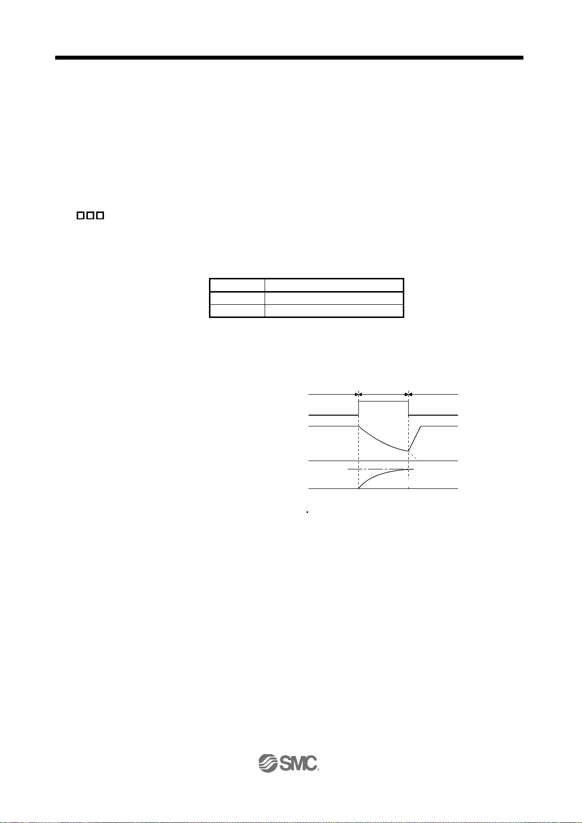
3. SIGNALS AND WIRING
(Note) LOP
Servo control mode
0
Speed control mode
1
Torque control mode
10V
0
ON
OFF
Torque
control mode
Servo motor speed
Control change (LOP)
(Note)
Speed
control mode
Speed
control mode
Analog torque
command (TC)
Load torque
Forward rotation in driving mode
The speed may be changed during rotation. In this case, the values set in parameters No.PC01 and
PC02 are used for acceleration/deceleration.
When the internal speed command 1 to 7 is used to command the speed, the speed does not vary with
the ambient temperature.
(c) Speed reached (SA)
As in section 3.6.2 (2).
3.6.5 Speed/torque control change mode Set "
3" in parameter No.PA01 to switch to the speed/torque control change mode.
(1) Control change (LOP)
Use control change (LOP) to switch between the speed control mode and the torque control mode from an
external contact. Relationships between LOP and control modes are indicated below.
Note. 0: off
1: on
The control mode may be changed at any time. A change timing chart is shown below.
(2) Speed setting in speed control mode
As in section 3.6.2 (1).
(3) Torque limit in speed control mode
As in section 3.6.1 (5).
Note. When the start (ST1 ST2) is switched off as soon as the mode is changed to
speed control, the servo motor comes to a stop according to the deceleration time
constant.
3 - 45

3. SIGNALS AND WIRING
SP1
DOCOM
P15R
VLA
LG
SD
Japan resistor
RRS10 or equivalent
(Note)
2k
2k
Servo amplifier
(Note) Input device
SP1
0
Analog speed limit (VLA)
1
Internal speed limit 1 (parameter No.PC05)
Driver
(4) Speed limit in torque control mode
(a) Speed limit value and speed
The speed is limited to the limit value set in parameter No.8 (internal speed limit 1) or the value set in
the applied v ol ta ge of the ana lo g s pee d l i mit (VLA). A relations hi p betwe en th e an al og spe ed limit (VLA)
applied voltage and the servo motor speed is as in section 3.6.3 (3) (a).
Generally, make connection as shown below.
Note. For the sink I/O interface. For the source I/O interface, refer to section 3.8.3.
(b) Speed selection 1 (SP1) and speed limit value
Use speed selection 1 (SP1) to select between the speed set by the internal speed limit 1 and the
speed set by the analog speed limit (VLA) as indicated in the following table.
Note. 0: off
When the internal speed limit 1 is used to command the speed, the speed does not vary with the
ambient temperature.
(c) Limiting speed (VLC)
As in section 3.6.3 (3) (c)
(5) Torque control in torque control mode
As in section 3.6.3 (1).
(6) Torque limit in torque control mode
As in section 3.6.3 (2).
Speed command value
1: on
3 - 46

3. SIGNALS AND WIRING
(Note) LOP
Servo control mode
0
Torque control mode
1
Position control mode
0V
10V
ON
OFF
ON
OFF
Servo motor speed
Zero speed detection (ZSP)
Control change (LOP)
Zero speed
level
Speed
control mode
Torque
control mode
Speed
control mode
Analog torque
command (TC)
3.6.6 Torque/position control change mode Set "
5 " in parameter No.PA01 to switch to the torque/position control change mode.
(1) Control change (LOP)
Use control change (LOP) to switch between the torque control mode and the position control mode from
an external contact. Relationships between LOP and control modes are indicated below.
Note. 0: off
1: on
The control mode may be changed in the zero speed status.
To ensure safety, change control after the servo motor has stopped. When position control mode is
changed to torque control mode, droop pulses are reset.
If the LOP has been switched on-off at the speed higher than the zero speed and the speed is then
reduced to the zero speed or less, the control mode cannot be changed. A change timing chart is shown
below.
(2) Speed limit in torque control mode
As in section 3.6.3 (3).
(3) Torque control in torque control mode
As in section 3.6.3 (1).
(4) Torque limit in torque control mode
As in section 3.6.3 (2).
(5) Torque limit in position control mode
As in section 3.6.1 (5).
3 - 47

3. SIGNALS AND WIRING
ON
OFF
ON
OFF
ON
OFF
ON
OFF
ON
OFF
ON
OFF
1s
Brake operation
15 to 60ms (Note 2)
Alarm occurs.
Remove cause of trouble.
Brake operation
Power off
Power on
Valid
Invalid
Main circuit
control circuit
power supply
Base circuit
Dynamic brake
Servo-on
(SON)
Reset
(RES)
Ready
(RD)
Trouble
(ALM)
(Note 1)
50ms or longer
3.7 Alarm occurrence timing chart When an alarm has occurred, remove its cause, make sure that the operation signal
CAUTION
is not being input, ensure safety, and reset the alarm before restarting operation.
As soon as an alarm occurs, turn off Servo-on (SON) and power off.
When an alarm occurs in the driver, the base circuit is shut off and the servo motor is coated to a stop. Switch
off the main circuit power supply in the external sequence. To reset the alarm, switch the control circuit power
supply from off to on, press the " SET " button on the current alarm screen, or turn the reset (RES) from off to
on. However, the alarm cannot be reset unless its cause is removed.
Note 1. Shut off the main circuit power as soon as an alarm occurs.
2. Changes depending on the operating status.
(1) Overcurrent, overload 1 or overload 2
If operation is repeated by switching control circuit power off, then on to reset the overcurrent (AL.32),
overload 1 (AL.50) or overload 2 (AL.51) alarm after its occurrence, without removing its cause, the driver
and servo motor may become faulty due to temperature rise. Securely remove the cause of the alarm and
also allow about 30 minutes for cooling before resuming operation.
(2) Regenerative alarm
If operation is repeated by switching control circuit power off, then on to reset the regenerative (AL.30)
alarm after its occurrence, the external regenerative resistor will generate heat, resulting in an accident.
(3) Instantaneous power failure
Undervoltage (AL.10) occurs when the input power is in either of the following statuses.
A power failure of the control circuit power supply continues for 60ms or longer, then the power restores.
During the servo-on status, the bus voltage dropped to 200VDC or less for LECSB2-□, 158VDC or less
for LECSB1-□.
(4) In position control mode (incremental)
When an alarm occurs, the home position is lost. When resuming operation after deactivating the alarm,
make a home position return.
3 - 48

3. SIGNALS AND WIRING
10VDC
D
3
DOCOM
SON SON SON
CN1
15
SP2 SP2 16
PC ST1 RS2 17
TL ST2 RS1 18
RES RES 19
CR SP1 41
EMG 42
LSP 43
LSN 44
LOP 45
46
OPC 12
20
47
PP 10
PG 11
NP 35
NG 36
LSP
LSN
LOP
DICOM
DOCOM
LOP
RES
SP1
P S T
CN1
21
22
23
24
25
48
49
DICOM
INP SA
ZSP
INP
TLC
RD
ZSP
TLC
ALM
RD
ZSP
TLC
RD
SA
P S T
CN1 P S T
4
5
6
7
8
9
33
34
5
4
3
6
1
7
CN3 P S T
LA
LAR
LB
LBR
LZ
LZR
OP
LG
SDP
SDN
RDP
RDN
LG
LG
CN6
P
S T
MO1
MO2
LG
3
2
1
Differential line
driver output
(35mA or less)
Open collector
output
CN1P S T
2VC VLA
27TLA
TLA
TC
1P15R
3
LG
28LG
30LG
Case
SD
(Note 2)
<Isolated>
15VDC
Approx. 5.6k
RS-422
Analog monitor
Servo amplifier
24VDC
CN2 P S T
2
4
7
8
MR
MRR
MD
MDR
LG
Encoder
E
Servo motor
(Note 3)
(Note 3)
USB
M
P S T
D
GND
VBUS 1
2
3
5
CN5
(Note 1)
(
Note 1)
(Note 1)
(Note 1)
(Note 1)
(Note 1)
(Note 1)
(Note 1)
RA
RA
Approx. 5.6k
Approx. 100k
Approx. 100k
Approx. 1.2k
Approx. 1.2k
10VDC
Driver
(Note 4)
(Note 4)
Encoder Z-phase pulse
Encoder A / B / Z-phase pulse
3.8 Interfaces
3.8.1 Internal connection diagram
3 - 49

3. SIGNALS AND WIRING
DOCO 46
OPC 12
20
47
PP 10
PG 11
NP 35
NG 36
DICOM
DOCOM
24VDC
SON,
etc.
Servo amplifier
Switch
Approx. 5mA
For transistor
DICOM
V
CES
1.0V
I
CEO
100 A
TR
24VDC 10
300mA
Approx. 5.6k
(Note)
Servo amplifier
ALM,
etc.
Load
DOCOM
If polarity of diode is
reversed, servo
amplifier will fail.
24VDC 10
300mA
Driver
Driver
driver
Note 1. P: Position control mode S: Speed control mode T: Torque control mode
2. For the differential line driver pulse train input. For the open collector pulse train input, make the following connection.
If the command pulse train input is open collector method, it supports only to the sink (NPN) type interface.
It does not correspond to the source (PNP) type interface.
3. For the sink I/O interface. For the source I/O interface, refer to section 3.8.3.
4. Encoder Z-phase pulse will correspond to the differential line driver system and the open collector system.
If the encoder Z-phase pulse is open collector method, it supports only to the sink (NPN) type interface. It does not correspond
to the source (PNP) type interface.
3.8.2 Detailed description of interfaces This section provides the details of the I/O signal interfaces (refer to the I/O division in the table) given in
section 3.5. Refer to this section and make connection with the external equipment.
(1) Digital input interface DI-1
Give a signal with a relay or open collector transistor. Refer to section 3.8.3 for source input.
(2) Digital output interface DO-1
A lamp, relay or photocoupler can be driven. Install a diode (D) for an inductive load, or install an inrush
current suppressing resistor (R) for a lamp load. (Rated current: 40mA or less, maximum current: 50mA or
less, inrush current: 100mA or less) A maximum of 2.6V voltage drop occurs in the driver.
Refer to section 3.8.3 for the source output.
Note. If the voltage drop (maximum of 2.6V) interferes with the relay operation, apply high
voltage (up to 26.4V) from external source.
3 - 50

3. SIGNALS AND WIRING
SD
PG(NG)
PP(NP)
Max. input pulse
frequency 1Mpps
Servo amplifier
Am26LS31 or equivalent
Approx. 100
V
OH
V
OL
(Note)
10m or less
: 2.5V
: 0.5V
0.9
0.1
tc
tHL
tc tLH
tF
tLH=tHL<0.1 s
tc>0.35 s
tF>3 s
PP PG
NP NG
Driver
(3) Pulse train input interface DI-2
Give a pulse train signal in the differential line driver system or open collector system.
(a) Differential line driver system
1) Interface
Note. Pulse train input interface is comprised of a photo coupler.
Therefore, it may be any malfunctions since the current is reduced when connect a
resistance to a pulse train signal line.
2) Input pulse condition
3 - 51

3. SIGNALS AND WIRING
Approx. 1.2k
Servo amplifier
24VDC
OPC
PP,
NP
DOCOM
SD
Max. input
pulse
frequency 200kpps
2m or less
(Note)
0.9
0.1
tc
tHL
tc
tLH
tF
tLH=tHL<
0.2 s
tc>2 s
tF>3
s
PP
NP
Driver
(b) Open collector system
1) Interface
2) Input pulse condition
Note. Pulse train input interface is comprised of a photo coupler.
Therefore, it may be any malfunctions since the current is reduced when connect a
resistance to a pulse train signal line.
If the command pulse train input is open collector method, it supports only to the sink
(NPN) type interface.
It does not correspond to the source (PNP) type interface.
3 - 52

3. SIGNALS AND WIRING
Photocoupler
Servo amplifier
OP
LG
SD
Servo amplifier
OP
LG
SD
5 to
24VDC
Servo amplifier
LA
(LB, LZ)
LAR
(LBR, LZR)
SD
LG
150
Am26LS32 or equivalent
High-speed photocoupler
Servo amplifier
LAR
(LBR, LZR)
SD
100
LA
(LB, LZ)
Servo motor CCW rotation
LA
LAR
LB
LBR
LZ
LZR
T
/2
OP
Time cycle (T) is determined by the settings
of parameter No.PA15 and PC19.
400 s or longer
Driver
Driver
Driver
Driver
(4) Encoder output pulse DO-2
Encoder Z-phase pulse wil l correspond to the differential line driver system and the open collector
system.
(a) Open collector system
Interface
Max. output current: 35mA
If the encoder Z-phase pulse is open collector method, it supports only to the sink (NPN) type
interface. It does not correspond to the source (PNP) type interface.
(b) Differential line driver system (Encoder A / B / Z-phase pulse)
1) Interface
Max. output current: 35mA
2) Output pulse
3 - 53

3. SIGNALS AND WIRING
Upper limit setting 2k
15VDC
P15R
VC, etc
LG
SD
2k
Servo amplifier
Approx.
10k
LG
MO1
Servo amplifier
(MO2)
Output voltage: 10V (Note)
Max. Output current: 1mA
Resolution: 10 bits or equivalent
Driver
Driver
(5) Analog input
Input impedance 10 to 12k
(6) Analog output
Note. Output voltage range varies depending on the monitored signal. (Refer to section
5.3.3.)
When connecting an analog output to an external device, use one whose withstand
voltage is
15VDC or more.
3 - 54

3. SIGNALS AND WIRING
Servo amplifier
Switch
Approx. 5mA
V
CES
1.0V
I
CEO
100 A
24VDC 10
300mA
Approx. 5.6k
SON,
etc.
DICOM
(Note)
If polarity of diode is
reversed, servo
amplifier will fail.
24VDC 10
300mA
Servo amplifier
ALM,
etc.
Load
DOCOM
Driver
Driver
driver
3.8.3 Source I/O interfaces In this driver, source type I/O interfaces can be used. In this case, all DI-1 input signals and DO-1 output
signals are of source type. Perform wiring according to the following interfaces.
(1) Digital input interface DI-1
(2) Digital output interface DO-1
A maximum of 2.6V voltage drop occurs in the driver.
Note. If the voltage drop (maximum of 2.6V) interferes with the relay operation, apply high
voltage (up to 26.4V) from external source.
3 - 55

3. SIGNALS AND WIRING
External conductor Sheath
External conductor
Pull back the external conductor to cover the sheath.
SheathCore
Strip the sheath.
Screw
Screw
Ground plate
Cable
Screw
Cable
Ground plate
3.9 Treatment of cable shield external conductor In the case of the CN1 and CN2 connectors, securely connect the shielded external conductor of the cable to the ground plate as shown in this section and fix it to the connector shell.
(1) For CN1 connector (Sumitomo 3M Limited connector)
(2) For CN2 connector (Sumitomo 3M Limited or Molex connector)
3 - 56

3. SIGNALS AND WIRING
POINT
Servo
amplifier
Servo motor
PE terminal
Control box
Driver
3.10 Connection of driver and servo motor During power-on, do not open or close the motor power line. Otherwise, a
WARNING
malfunction or faulty may occur.
3.10.1 Connection instructions
WARNING
Insulate the connections of the power supply terminals to prevent an electric shock.
Connect the wires to the correct phase terminals (U, V, W) of the driver and servo
motor. Not doing so may cause unexpected operation.
Do not connect AC power supply directly to the servo motor. Otherwise, a fault may
CAUTION
occur.
Do not use the 24VDC interface power supply for the electromagnetic brake. Always
use the power supply designed exclusively for the electromagnetic brake.
Otherwise, a fault may occur.
Refer to section 12.1 for the selection of the encoder cable.
Refer to the Servo Motor Instruction Manual (Vol.2) for the selection of a surge
absorber for the electromagnetic brake.
This section indicates the connection of the motor power supply (U, V, W). Use of the optional cable or
connector set is recommended for connection between the driver and servo motor. Refer to section 12.1 for
details of the options.
(1) For grounding, connect the earth cable of the servo motor to the protective earth (PE) terminal of the driver
and connect the ground cable of the driver to the earth via the protective earth of the control box. Do not
connect them directly to the protective earth of the control panel.
(2) Do not use the 24VDC interface power supply for the lock. Always use the power supply designed
exclusively for the lock.
3 - 57

3. SIGNALS AND WIRING
CNP3
AWG 19 (red)
AWG 19 (white)
AWG 19 (black)
AWG 19 (green/yellow)
W
V
U
Servo motorServo amplifier
10m or less
MR-PWS1CBL M-A1-L
MR-PWS1CBL M-A2-L
MR-PWS1CBL M-A1-H
MR-PWS1CBL M-A2-H
M
U
V
W
MR-PWS1CBL2M-A1-L
MR-PWS1CBL2M-A2
-L
MR-PWS1CBL2M-A1-H
MR-PWS1CBL2M-A2-H
MR-PWS2CBL03M-A1-L
MR-PWS2CBL03M-A2-L
CNP3
AWG 19 (red)
AWG 19 (white)
AWG 19 (black)
U
V
W
Servo motor
Servo amplifier
Extension cable
50m or less
2m or less
U
VWM
AWG 19 (green/yellow)
(Note)
a) Relay connector for
extension cable
(Note)
b) Relay connector for motor
power supply cable
Relay connector
Description
IP rating
Numeral changes depending on the cable OD.
Connector: RM15WTPZ-4P(71)
Cord clamp: JR13WCC-5(72)
(Hirose Electric)
IP65
b) Relay connector for
cable
Numeral changes depending on the cable OD.
Connector: RM15WTJZ-4S(71)
Cord clamp: JR13WCC-8(72)
(Hirose Electric)
IP65
Driver
Driver
LE-CSM-
LE-CSM-
3.10.2 Power supply cable wiring diagrams (1) LE-□-□ series servo motor
(a) When cable length is 10m or less
(b) When cable length exceeds 10m
When the cable length exceeds 10m, fabricate an extension cable as show n bel ow . In thi s ca se, the
motor power supply cable should be within 2m long.
Refer to section 12.5 for the wire used for the extension cable.
□□□
□□□
Note. Use of the following connectors is recommended when ingress protection (IP65) is
a) Relay connector for
extension cable
motor power supply
necessary.
3 - 58

3. SIGNALS AND WIRING
Servo motor
Electromagnetic brake
B
RA
Contacts must be opened
with the EMG stop switch.
Contacts must be opened when ALM
(Malfunction) or MBR (Electromagnetic
brake interlock) turns off.
24 V DC
POINT
Lock
Contacts must be opened when ALM (Malfunction)
off.
Refer to section 3.11.4 when wiring for the circuit configuration.
3.11 Servo motor with a lock
3.11.1 Safety precautions Configure a lock circuit so that it is activated also by an external emergency stop
switch.
and MBR (Electromagnetic brake interlock) turns
CAUTION
The lock is provided for holding purpose and must not be used for ordinary braking.
Before performing the operation, be sure to confirm that the lock operates properly.
Do not use the 24VDC interface power supply for the lock. Always use the power
supply designed exclusively for the lock. Otherwise, a fault may occ ur .
Refer to chapter 15 for specifications such as the power supply capacity and
operation delay time of the lock.
Refer to chapter 15 for the selection of a surge absorber for the lock.
Note the following when the servo motor with a lock is used.
1) Set " 1" in parameter No.PA04 to make the electromagnetic brake interlock (MBR) valid.
2) The lock will operate when the power (24VDC) switches off.
3) While the res et (RES) is on, th e base circuit is shut off. W hen using the serv o motor with a v ertical
shaft, use the electromagnetic brake interlock (MBR).
4) Switch off the servo-on (SON) after the servo motor has stopped.
3.11.2 Setting (1) Set "
1" in parameter No.PA04 to make the electromagnetic brake interlock (MBR) valid.
(2) Using parameter No.PC16 (electromagnetic brake sequence output), set a delay time (Tb) at servo-off from
lock operation to base circuit shut-off as in the timing chart shown in section 3.11.3(1).
3 - 59

3. SIGNALS AND WIRING
(95ms)
(95ms)
Electromagnetic
brake interlock
(MBR)
(Note 1) ON
OFF
ON
OFF
0 r/min
Base circuit
Servo motor speed
Servo-on (SON)
ON
OFF
Coasting
Tb
Electromagnetic
brake operatio n
delay time
Release
Activate
Position comma nd
(Note 4)
Electromagnetic
brake
Release delay time and external relay (Note 2)
(Note 3)
0 r/min
Servo motor speed
Electromagnetic
brake interlock (MBR)
ON
OFF
Base circuit
(Note) ON
OFF
Emergency stop (EMG)
(10ms)
(210ms)
(210ms)
Dynamic brake
Dynamic brake
Electromagnetic brake
Electromagnetic brake
Invalid (ON)
Valid (OFF)
Electromagnetic brake
operation delay time
Electromagnetic brake release
Lock
Lock
Lock
Lock
Lock release
3.11.3 Timing charts (1) Servo-on (SON) command (from driver) ON/OFF
Tb [ms] after the servo-on (SON) signal is switched off, the servo lock is released and the servo motor
coasts. If the lock is made valid in the servo lock status, the lock life may be shorter. Therefore, when using
the lock in a vertical lift application or the like, set Tb to about the same as the lock operation del ay ti me t o
prevent a drop.
Note 1. ON: Lock is not activated.
OFF: Lock is activated.
2. Lock is released after delaying for the release delay time of lock and operation t ime of external ci rcuit rel ay. For the release
delay time of lock, refer to chapter 15.
3. Give a position command after the lock is released.
4. For the position control mode.
(2) Emergency stop (EMG) ON/OFF
Note. ON: Lock is not activat ed.
OFF: Lock is activated.
3 - 60

3. SIGNALS AND WIRING
Servo motor speed
ON
OFF
Base circuit
Electromagnetic
brake interlock (MBR)
(Note) ON
OFF
Trouble (ALM)
No (ON)
Yes (OFF)
Dynamic brake
Dynamic brake
Electromagnetic brake
Electromagnetic brake
operation delay time
Electromagnetic brake
(10ms)
(10ms)
Dynamic brake
Dynamic brake
Electromagnetic brake
Electromagnetic brake
(Note 1)
15 to 60ms
Electromagnetic brake
operation delay time
(Note 2) ON
OFF
Electromagnetic
brake interlock
(MBR)
ON
OFF
Base circuit
Servo motor speed
No (ON)
Yes (OFF)
Trouble (ALM)
ON
OFF
Main circuit
Control circuit
power
10ms
Lock
Lock
Lock
Lock
Lock operation
delay time
Lock operation
delay time
(3) Alarm occurrence
Note. ON: Lock is not acti vat ed.
OFF: Lock is activated.
(4) Both main and control circuit power supplies off
Note 1. Changes with the operating status.
2. ON: Lock is not activated.
OFF: Lock is activated.
3 - 61

3. SIGNALS AND WIRING
Servo motor speed
ON
OFF
Base circuit
Electromagnetic
brake interlock
(MBR)
(Note 2) ON
OFF
Trouble (ALM)
No (ON)
Yes (OFF)
ON
OFF
Main circuit power
supply
Dynamic brake
Dynamic brake
Electromagnetic brake
Electromagnetic brake
Electromagnetic brake
operation delay time
(10ms)
(Note 1)
15ms or longer
10m or less
Electromagnetic
brake interlock
(MBR)
AWG20
AWG20
(Note 1)
B1
B2
Trouble
(ALM)
Servo motor
B
(Note 4)
(Note 2)
MR-BKS1CBL
M-A1-L
MR-BKS1CBL M-A
2-L
MR-
BKS1CBL M-A1-H
MR-BKS1CBL M-
A2-H
24VDC power
supply for
electromagnetic
brake
(Note 5)
(Note 3)
Lock
Lock
Lock operation
delay time
lock
(5) Only main circuit power supply off (control circuit power supply remains on)
Note 1. Changes with the operating status.
2. ON: Lock is not activated.
OFF: Lock is activated.
3.11.4 Wiring diagrams (LE-□-□ series servo motor)
(1) When cable length is 10m or less
When fabricating the lock cable LE-CSB-R□A, refer to section 12.1.4.
Note 1. Connect a surge absorber as close to the servo motor as possible.
2. There is no polarity in lock t erminals (B 1 and B2).
3. When using a servo motor with a lock, assign the electromagnetic brake interlock (MBR) to
external output signal in the parameters No.PA04, PD13 to PD16 and PD18.
4. Shut off the circuit by interlocking with the emergency stop switch.
5. Do not use the 24VDC interface power supply for the lock.
3 - 62
LE-CSB-□□□

3. SIGNALS AND WIRING
(Note 2)
a) Relay connector for
extension cable
B
MR-BKS1CBL2M-A1-L
MR-BKS1CBL2M-A2-L
MR-BKS1CBL2M-A1-H
MR-BKS1CBL2M-A2-H
MR-BKS2CBL03M-A1-L
MR-BKS2CBL03M-A2-L
2m or less
50m or less
Electromagnetic
brake interlock
(MBR)
AWG20
AWG20
(Note 1)
B1
B2
Trouble
(ALM)
Servo motor
(Note 5)
(Note 3)
24VDC power
supply for
electromagnetic
brake
(Note 2)
b) Relay connector for motor
brake cable
Extension cable
(To be fabricated)
(Note 6)
(Note 4)
Relay connector
Description
IP rating
CM10-CR2P(DDK)
Wire size: S, M, L
lock cable
CM10-SP2S- (D6)
(DDK)
Wire size: S, M, L
LE-CSB
lock
lock cable
(2) When cable length exceeds 10m
When the cable length exceeds 10m, fabricate an extension cable as shown below on the customer side. In
this case, the lock cable should be within 2m long.
Refer to section 12.11 for the wire used for the extension cable.
-□□□
Note 1. Connect a surge absorber as close to the servo motor as possible.
2. Use of the following connectors is recommended when ingress protection (IP65) is necessary.
a) Relay connector for
extension cable
b) Relay connector for
IP65
IP65
3. There is no polarity in lock t erminals (B 1 and B2).
4. When using a servo motor with a lock, assign the electromagnetic brake interlock (MBR) to
external output signal in the parameters No.PA04, PD13 to PD16 and PD18.
5. Shut off the circuit by interlocking with the emergency stop switch.
6. Do not use the 24VDC interface power supply for the lock.
3 - 63

3. SIGNALS AND WIRING
(Note)
Power supply
W
V
U
Ensure to connect it to PE
terminal of the servo amplifier.
Do not connect it directly to the
protective earth of the control
panel.
Control box
Servo motor
M
U
V
W
Encoder
CN2
Servo amplifier
L
11
L
1
L
2
L
3
L
21
CN1
Protective earth (PE)
Outer
box
MC
NFB
Line filter
Programmable
controller
Driver
driver.
PC or
3.12 Grounding Ground the driver and servo motor securely.
WARNING
To prevent an electric shock, always connect the protective earth (PE) terminal
(terminal marked
) of the driver with the protective earth (PE) of the control box.
The driver switches the power transistor on-off to supply power to the servo motor. Depending on the wiring
and ground cable routing, the driver may be affected by the switching noise (due to di/dt and dv/dt) of the
transistor. To prevent such a fault, refer to the following diagram and always ground.
To conform to the EMC Directive, refer to the EMC Installation Guidelines (IB(NA)67310).
PLC…etc
Note. For 1-phase 200 to 230VAC or 1-phase 100 to 120VAC, connect the power supply to L1 L2 and leave L3 open.
There is no L3 for 1-phase 100 to 120VAC power supply. For the specification of power supply, ref er to secti on 1.3.
3 - 64
 Loading...