


No.JXC※-OMW1019-A
PRODUCT NAME
Step Motor Controller
With Step data Teaching Function
(Servo / 24VDC)
MODEL / Series / Product Number
LECP6###-#-XB120
(Number of Step Data: 32 points)
Supplementary
Operation Manual

- 1 -
No.JXC※-OMW1019-A
●Scope of the supplementary operation manual
Applicable Product No.: LECP6###-#-XB120
Applicable model: LECP6 controller
Product specification with teaching function
(Number of Step Data: 32 points)
This supplementary operation manual specifies only the “Product specification
with teaching function” as well as the changes between this special product
and the standard LECP6 series step motor controller due to the addition of the
teaching function.
Refer to Operation Manual "LECP6 series Step Motor Controller” for handling
method and precautions other than “Positional registration function with
parallel I/O”

- 2 -
No.JXC※-OMW1019-A
Contents
1. Safety Instructions 3
2. Product Outline 5
2.1 Product features 5
2.2 How to Order 6
2.3 Startup Procedures (changed) 7
3. Product Specifications 7
3.1 Outside dimension diagram 7
(1) Screw mount type (LECP6##-#-X120) 7
(2) DIN rail mount type (LECP6##D-#-XB120) 8
3.2 How to install 8
4. CN5: Parallel l/O Connector 9
4.1 Parallel I/O signals (changed) 9
(1) When the MODE input (Terminal No. A8) is OFF 9
(2) When the MODE input (Terminal No. A8) is ON 12
4.2 Parallel I/O Wiring Example 13
5. Setting Data Entry 15
6. Supplementary setting data input 15
7. Supplementary operation instruction mode 16
7.1 Operation when MODE is ON (Jog operation, teaching) 16
(1) Jog operation 16
(2) Teaching 17
8. Wiring of cables / Common precautions 18
9. Electric actuators / Common precautions 19
9.1 Design and selection 19
9.2 Mounting 20
9.3 Precautions for Use 20
9.4 Operating environment 21
9.5 Maintenance 22
9.6 Precautions for electric actuator with lock 23
10. Controller and its peripheral devices / Specific product precautions 23
10.1 Design and selection 23
10.2 Handling 24
10.3 Installation 25
10.4 Wiring 25
10.5 Power supply 25
10.6 Grounding 26
10.7 Maintenace 26
- 3 -
No.JXC※-OMW1019-A
LECP6 Series / Controller
1. Safety Instructions
These safety instructions are intended to prevent hazardous situations and/or equipment damage.
These instructions indicate the level of potential hazard with the labels of "Caution", "Warning" or "Danger".
They are all important notes for safety and must be followed in addition to International Standards
(ISO/IEC)*1), and other safety regulations.
*1) ISO 4414: Pneumatic fluid power -- General rules relating to systems.
ISO 4413: Hydraulic fluid power -- General rules relating to systems.
IEC 60204-1: Safety of machinery -- Electrical equipment of machines. (Part 1: General requirements)
ISO 10218: Manipulating industrial robots -Safety.
etc.
Caution
Caution indicates a hazard with a low level of risk which, if not avoided, could
result in minor or moderate injury.
Warning
Warning indicates a hazard with a medium level of risk which, if not avoided,
could result in death or serious injury.
Danger
Danger indicates a hazard with a high level of risk which, if not avoided, will
result in death or serious injury.
Warning
1. The compatibility of the product is the responsibility of the person who designs the
equipment or decides its specifications.
Since the product specified here is used under various operating conditions, its compatibility with specific
equipment must be decided by the person who designs the equipment or decides its specifications
based on necessary analysis and test results.
The expected performance and safety assurance of the equipment will be the responsibility of the person
who has determined its compatibility with the product.
This person should also continuously review all specifications of the product referring to its latest catalog
information, with a view to giving due consideration to any possibility of equipment failure when
configuring the equipment.
2. Only personnel with appropriate training should operate machinery and equipment.
The product specified here may become unsafe if handled incorrectly.
The assembly, operation and maintenance of machines or equipment including our products must be
performed by an operator who is appropriately trained and experienced.
3. Do not service or attempt to remove product and machinery/equipment until safety is
confirmed.
1. The inspection and maintenance of machinery/equipment should only be performed after measures to
prevent falling or runaway of the driven objects have been confirmed.
2. When the product is to be removed, confirm that the safety measures as mentioned above are
implemented and the power from any appropriate source is cut, and read and understand the specific
product precautions of all relevant products carefully.
3. Before machinery/equipment is restarted, take measures to prevent unexpected operation and malfunction.
4. Contact SMC beforehand and take special consideration of safety measures if the
product is to be used in any of the following conditions.
1. Conditions and environments outside of the given specifications, or use outdoors or in a place
exposed to direct sunlight.
2. Installation on equipment in conjunction with atomic energy, railways, air navigation, space, shipping,
vehicles, military, medical treatment, combustion and recreation, or equipment in contact with food and
beverages, emergency stop circuits, clutch and brake circuits in press applications, safety equipment or
other applications unsuitable for the standard specifications described in the product catalog.
3. An application which could have negative effects on people, property, or animals requiring special
safety analysis.
4. Use in an interlock circuit, which requires the provision of double interlock for possible failure by using
a mechanical protective function, and periodical checks to confirm proper operation.
- 4 -
No.JXC※-OMW1019-A
LECP6 Series / Controller
1. Safety Instructions
Caution
1.The product is provided for use in manufacturing industries.
The product herein described is basically provided for peaceful use in manufacturing industries.
If considering using the product in other industries, consult SMC beforehand and exchange
specifications or a contract if necessary.
If anything is unclear, contact your nearest sales branch.
Limited warranty and Disclaimer/Compliance Requirements
The product used is subject to the following "Limited warranty and Disclaimer" and "Compliance
Requirements".
Read and accept them before using the product.
Limited warranty and Disclaimer
1. The warranty period of the product is 1 year in service or 1.5 years after the product is
delivered, whichever is first.2)
Also, the product may have specified durability, running distance or replacement parts.
Please consult your nearest sales branch.
2. For any failure or damage reported within the warranty period which is clearly our
responsibility, a replacement product or necessary parts will be provided.
This limited warranty applies only to our product independently, and not to any other
damage incurred due to the failure of the product.
3. Prior to using SMC products, please read and understand the warranty terms and
disclaimers noted in the specified catalog for the particular products.
2) Vacuum pads are excluded from this 1 year warranty.
A vacuum pad is a consumable part, so it is warranted for a year after it is delivered.
Also, even within the warranty period, the wear of a product due to the use of the
vacuum pad or failure due to the deterioration of rubber material are not covered by the
limited warranty.
Compliance Requirements
1. The use of SMC products with production equipment for the manufacture of weapons of
mass destruction (WMD) or any other weapon is strictly prohibited.
2. The exports of SMC products or technology from one country to another are governed by
the relevant security laws and regulation of the countries involved in the transaction. Prior
to the shipment of a SMC product to another country, assure that all local rules governing
that export are known and followed.
Caution
SMC products are not intended for use as instruments for legal metrology.
Products that SMC manufactures or sells are not measurement instruments that are qualified by pattern
approval tests relating to the measurement laws of each country.
Therefore, SMC products cannot be used for business or certification ordained by the measurement laws of
each country.
- 5 -
No.JXC※-OMW1019-A
2. Product Outline
2.1 Product features
This controller can provide the JOG operation and teaching operation by switching the functions using
the MODE input.
●
U
32 points positioning / pushing are available (MODE=OFF)
Control the electric actuator according to the step data specified by the input of parallel I/O.
It is possible to set up various parameters for each operation pattern.
●
U
Jog operation is available via the parallel I/O (MODE=ON)
It is possible to instruct the jog operation using JOG- input and JOG+ input via the parallel I/O.
● Teaching is available via parallel I/O (MODE=ON)
It is possible to register the current position in the step data via the parallel I/O.
Caution
Please keep this manual safe for future use. It will be necessary to refer to this manual along with the
operation manuals for other electric actuators, teaching box, and controller setting kit at installation and
fault finding.
Keep this operation manual accessible for reference.
- 6 -
No.JXC※-OMW1019-A
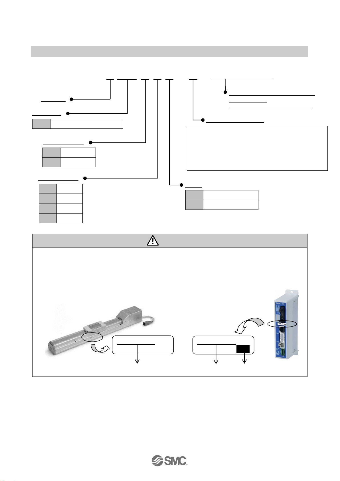
2.2 How to Order
The part number construction for this product is as follows:
LECP6N□□-□- XB120
U
Controller
UCompatible
Electric actuator model
U
Parallel I/O type
I/O cable length
Option
Caution
Products are shipped after setting the electric actuator specification parameters.
Confirm the combination of the controller and the electric actuator is correct.
<Check the following before use.>
(1) Check the electric actuator label for the model number. Check that this matches the controller.
(2) Check Parallel I/O configuration matches (NPN or PNP)
Controller
(1) (1) (2)
With JOG input terminal, WAREA
output function
(Number of step data: 32 points)
Stroke example: For LEFS25B-100B-S36N1,
specify LEFS25B-100.
Rotating angle: For LER10K-2L-R16N1D,
specify LER10K-2.
(Enter from the electric actuator part number “LE” to
“stroke / rotating angle”)
DIN rail mounting
Screw mounting
1.5m
1
None
Nil
3m
3
5m
5
PNP type
P
NPN type
N
Step motor(Servo / 24VDC)
P6
LEFS25B-100
NP N
LEFS25B-100
Electric actuator
- 7 -
No.JXC※-OMW1019-A
Controller
Power supply plug
I/O cable
2.3 Startup Procedures (changed)
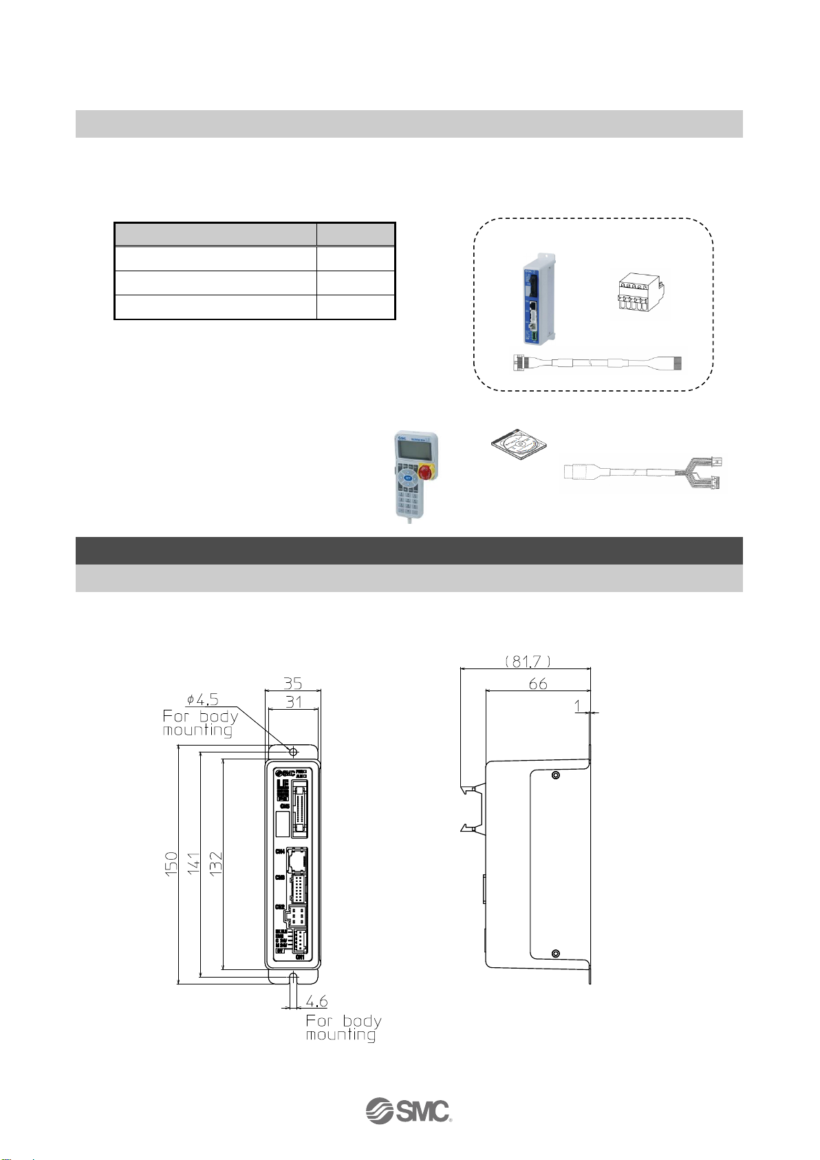
Confirmation of the package content
After unpacking everything, check the description on the label to identify the controller and the number of
accessories. If any parts are missing or damaged, please contact your distributor.
*1) Included in the package only when the I/O cable length is
specified.
【
Option
】
●Teaching box
●Controller setting kit
●
Actuator cable
●I/O cable
3. Product Specifications
3.1 Outside dimension diagram
The outside view of this product is as shown in the diagram below:
(1) Screw mount type (LECP6##-#-X120)
Item
Quantity
Controller (LECP6###-#-XB55)
1 unit
Power supply plug (LEC-D1-1)
1 piece
I/O cable (LEC-CN5-#)
*1)
1 piece
Teaching box Controller setting kit
Actuator cable
- 8 -
No.JXC※-OMW1019-A
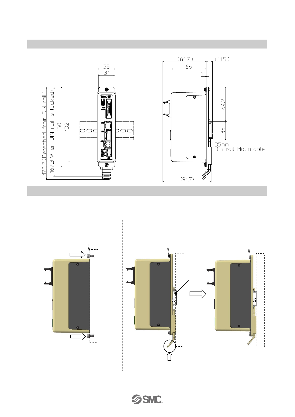
(2) DIN rail mount type (LECP6##D-#-XB120)
3.2 How to install
How to install
The controller can be direct mounted using screws or mounted on a DIN rail.
The followings are the descriptions on how to install each type:
1) Screw mount type 2) DIN rail mount type
(LECP6##-#-XB120) (LECP6##D-#-XB120)
(Installation with two M4 screws) (Installation with the DIN rail)
Screw direction
Screw direction
Ground wire
Ground wire
DIN rail
DIN rail is locked.
Ground wire
A
Hook the controller on the DIN rail and
press the lever of section A in the arrow
direction to lock it.

- 9 -
No.JXC※-OMW1019-A
4. CN5: Parallel l/O Connector
4.1 Parallel I/O signals (changed)
Parallel input / output signal functions can be switched using the MODE input (terminal No. A8).
Functions when the MODE input is OFF and ON are explained as follows.
I/Ocable
Connector for CN5 of the controller The end to be connected to a PLC, etc.
(1) When the MODE input (Terminal No. A8) is OFF
- Input terminal-
No.
Function
Description
A3
INO
Bit no. to specify the step data
(Specify the number by combining On / Off of the terminals.)
IN4
IN3
IN2
IN1
IN0
OFF
OFF
OFF
ON
ON
0 0 0 1 1
A4
IN1
A5
IN2
A6
IN3
A7
IN4
A8
MODE
The input / output signal functions are changed using this terminal.
This table shows the case when the MODE is OFF.
A9
SETUP
When SVRE (B11) is ON, the SETUP operation (return to origin operation) will be performed.
During the SETUP operation, BUSY (B7) will be turned ON and after completion of the
SETUP operation, SETON (B9) and INP (B10) will be turned ON.
A10
HOLD
If HOLD input is ON during operation, the speed decreases at maximum deceleration speed
of the basic parameter until the electric actuator stops. The remaining stroke will be on hold
as long as HOLD is ON and when HOLD is turned OFF, the electric actuator restart to travel
the remaining stroke.
● When DRIVE or SETUP is ON:
Caution
As long as HOLD is ON, the DRIVE input will be disabled.
The output signals are rendered invalid whilst hold is in operation.
A11
DRIVE
When DRIVE is turned ON, the system scans the input IN0 to IN4 and starts the operation of
the electric actuator. Then, when this terminal is turned OFF, the number of the active step
data will be output via the terminals OUT0 to OUT4.
A12
RESET
The terminal to reset the alarm and the operation. After RESET, the speed decreases at
maximum deceleration speed of the basic parameter until the electric actuator stops. INP
and OUT0 to OUT4 will be turned OFF (however, if the electric actuator is stopped within the
in-position range, the INP will be turned ON).
A13
SVON
The SVON signals turns the servomotor ON / OFF.
*1)
*1) When power is applied, it may take up to 10 seconds (max. 20 sec.) from SVON input to SVRE output depending on the electric
actuator position.
B1 A1
B13 A13
A1
・
・
・
A13
B1
・
・
・
B13
Binary code
On hold
ON
OFF
ON
OFF
Restart
DRIVE
or
SETUP
HOLD
Speed

- 10 -
No.JXC※-OMW1019-A
-Output terminal-
No.
Function
Description
B1
OUT0
When the operation is started and DRIVE is turned OFF, a Bit no. corresponding to the
number of the active step data will be output from these terminals.
This output signal will be updated when DRIVE (A11) terminal is be turned ON
Caution
(1) When RESET is turned ON, these terminals are turned OFF.
(2) During an alarm, these terminals output the alarm group.
(3) During a pushing operation, if the actuator runs over the defined pushing width, these
terminals will be turned OFF.
B2
OUT1
B3
OUT2
B4
OUT3
B5
OUT4
B6
MODE
Indicates the MODE input status.
This table shows the case when the MODE is OFF.
B7
BUSY
This terminal is ON during the movement of the electric actuator.
(During the positioning operation, etc.).
Caution
During the pushing operation without movement (no movement but the electric actuator
generating the pushing force), BUSY is OFF. BUSY signal stays on for 50ms or longer
after operation starts.
B8
AREA
When the electric actuator is within the range between Area 2 and Area1 in the step data,
this terminal will be turned ON. The range changes depending on the active step data.
B9
SETON
When the electric actuator is in the SETON status (the position information is established),
this terminal is turned ON.
When the position status is not established, this terminal is OFF.
B10
INP
The condition when the INP output is ON depends on the electric actuator operation.
●During return to origin operation
After stopping the electric actuator operation (turning OFF the BUSY output), the INP
turns ON when the actuator is within the range defined in the origin +/- “Default
positioning range” in the basic parameter.
● During positioning operation
Turns ON when the current position is within "Step data position +/- positioning range".
● During pushing operation.
When the pushing force exceeds the value set in the step data “Trigger LV”.
Caution
After pushing operation is finished, even if controller changes to energy saving mode,
“INP” signal status maintains to ON.
(Example) Step data “force” is 100%
Step data “Trigger LV” is 80%,
The energy saving setting of the
electric actuator is 40%
The electric actuator model determines the energy settings.Please
refer to the specifications of the electric actuator for more details.
If the stop is input from the EMG or RESET terminal or the stop-switch on the connected
Teaching Box during pushing operation, the electric actuator stop. (“Busy” signal turns OFF)
If the electric actuator stops within the range of “Position”± “In posn” as defined in the step
data, the output signal “INP” will turn ON.
INP (ON)
80
100
40
force

- 11 -
No.JXC※-OMW1019-A
B11
SVRE
When the servomotor is OFF, SVRE is OFF. When the servomotor is ON, SVRE is ON.
(*1)
B12
*ESTOP
*2)
During activation of Teaching Box stop switch, this terminal is OFF. During the normal
operation, this is ON. This is synchronized to the input terminal for the EMG signal on the
controller connector CN1.
B13
*ALARM
*2)
When there are no alarms, this terminal is ON.
When there are alarms, this is OFF.
*1) When power is applied, it may take up to 10 seconds (max. 20 sec.) from SVON input to SVRE output depending on the electric
actuator position.
*2) The “*ALARM” and “*ESTOP” are the negative-true logic output.

- 12 -
No.JXC※-OMW1019-A
(2) When the MODE input (Terminal No. A8) is ON
- Input terminal-
No.
Function
Description
A3
IN0
Step data instruction bit No. for writing the current position
(input is specified by combination of IN0 to IN4.)
Example: (Bit no. to specify the step data no.3.)
IN4
IN3
IN2
IN1
IN0
OFF
OFF
OFF
ON
ON
0 0 0 1 1
A4
IN1
A5
IN2
A6
IN3
A7
IN4
A8
MODE
The input / output signal functions are changed using this terminal.
This table shows the case when the MODE is ON.
A9
WRST
Teaching instruction signal
When the teaching instruction signal is ON, the current position is written to the
specified step data between IN0 and IN1.
A10
JOG+
When SVRE output is turned ON, the table moves in the positive direction in
accordance with the operation parameters “JOG speed” and “JOG acceleration”
while the JOG+ input is turned ON.
When ALARM and SVRE are turned ON, it is possible to instruct the JOG operation,
regardless of the SETON ON / OFF condition.
A11
JOG-
When SVRE output is turned ON, the table moves in the negative direction in
accordance with the operation parameters “JOG speed” and “JOG acceleration”
while the JOG- input is turned ON.
When ALARM and SVRE are turned ON, it is possible to instruct the JOG operation,
regardless of the SETON ON / OFF condition.
A12
RESET
Same as the description when the MODE (terminal No. A8) is turned OFF.
A13
SVON
Same as the description when the MODE (terminal No. A8) is turned OFF.
-Output terminal-
No.
Function
Description
B1
-
Unused (OFF)
B2
-
B3
-
B4 - B5
-
B6
MODE
Indicates the MODE input status.
This table shows the case when the MODE is OFF.
B7
BUSY
Same as the description when the MODE (terminal No. A8) is turned OFF.
*3
)
B8
AREA
Same as the description when the MODE (terminal No. A8) is turned OFF.
B9
WREND
Signal for showing the completion of the teaching data writing. This terminal turns
ON when writing of the current position is complete after turning ON the WRST. When
the WRST is turned OFF, WREND is also turned OFF.
B10
INP
Same as the description when the MODE (terminal No. A8) is turned OFF.
B11
SVRE
Same as the description when the MODE (terminal No. A8) is turned OFF.
B12
*ESTOP
Same as the description when the MODE (terminal No. A8) is turned OFF.
B13
*ALARM
Same as the description when the MODE (terminal No. A8) is turned OFF.
*3) The signal will be unstable (chattering occurs) in the JOG operation due to the lower speed of operation.

- 13 -
No.JXC※-OMW1019-A
4.2 Parallel I/O Wiring Example
When you connect a PLC, etc. to the CN5 parallel I/O connector, please use the I/O cable (LEC-CN5-#).
The wiring should be changed depending on the type of the parallel I/O (NPN or PNP).
Please wire referring to the following diagram.
The functions described in the wiring examples below show the case when the MODE is turned OFF.
● NPN type ● PNP type
Caution
The 24VDC controller power supply for CN1 and the 24VDC I/O power supply for CN5 should be
separated.
I/O signal power
24VDC
Load
Load
Load
Load
Load
Load
Load
Load
Load
Load
Load
Load
Load
Load
Load
Load
Load
Load
Load
Load
Load
Load
Load
Load
Load
Load
I/O signal power
24VDC
CN5
B1
*ESTOP
B1
*ALARM
B11
SVRE
B1
INP
B9
SETON
B8
AREA
B7
BUSY
B6
MODE
B5
OUT4
B4
OUT3
B3
OUT2
B2
OUT1
B1
OUT0
A1
SVON
A1
RESET
A11
DRIVE
A1
HOLD
A9
SETUP
A8
MODE
A7
IN4
A6
IN3
A5
IN2
A4
IN1
A3
IN0
A2
COM-
A1
COM+
*ESTOP
*ALARM
SVRE
INP
WREND
AREA
BUSY
MODE
- - -
- - SVON
RESET
JOG-
JOG+
WRST
MODE
IN4
IN3
IN2
IN1
IN0
COM-
COM+
MODE(A8)
OFF
MODE(A8)
ON
CN5
B1
*ESTOP
B1
*ALARM
B11
SVRE
B1
INP
B9
SETON
B8
AREA
B7
BUSY
B6
MODE
B5
OUT4
B4
OUT3
B3
OUT2
B2
OUT1
B1
OUT0
A1
SVON
A1
RESET
A11
DRIVE
A1
HOLD
A9
SETUP
A8
MODE
A7
IN4
A6
IN3
A5
IN2
A4
IN1
A3
IN0
A2
COM-
A1
COM+
*ESTOP
*ALARM
SVRE
INP
WREND
AREA
BUSY
MODE
- - - - -
SVON
RESET
JOG-
JOG+
WRST
MODE
IN4
IN3
IN2
IN1
IN0
COM-
COM+
MODE(A8)
OFF
MODE(A8)
ON

- 14 -
No.JXC※-OMW1019-A
The functions described in the wiring examples below show the case when the MODE is turned OFF.
●NPN Type ●PNP Type
CN5 CN5
B12
*ESTOP
B13
*ALARM
B11
SVRE
B10
INP
B9
SETON
B8
AREA
B7
BUSY
B6
MODE
B5
OUT4
B4
OUT3
B3
OUT2
B2
OUT1
B1
OUT0
A13
SVON
A12
RESET
A11
DRIVE
A10
HOLD
A9
SETUP
A8
MODE
A7
IN4
A6
IN3
A5
IN2
A4
IN1
A3
IN0
A2
COM-
A1
COM+
I/O signal power
24VDC
B12
*ESTOP
B13
*ALARM
B11
SVRE
B10
INP
B9
SETON
B8
AREA
B7
BUSY
B6
MODE
B5
OUT4
B4
OUT3
B3
OUT2
B2
OUT1
B1
OUT0
A13
SVON
A12
RESET
A11
DRIVE
A10
HOLD
A9
SETUP
A8
MODE
A7
IN4
A6
IN3
A5
IN2
A4
IN1
A3
IN0
A2
COM-
A1
COM+
I/O signal power
24VDC
Load
Load
Load
Load
Load
Load
Load
Load
Load
Load
Load
Load
Load
Load
Load
Load
Load
Load
Load
Load
Load
Load
Load
Load
Load
Load

- 15 -
No.JXC※-OMW1019-A
5. Setting Data Entry
Step data changes
Step data is the actual data relating to the operation of the electric actuator.
There are 32 patterns of step data. Each of them has 1 item to be set.
Each step data will become effective as soon as it is written to the controller.
Example) Step data of the controller setting kit [Normal mode]
No.
Move
Speed
mm/s
Position
mm
Accel
mm/s2
Decel
mm/s2
PushingF
%
TriggerLV
%
PushingSp
mm/s
Moving F
%
Area1
mm
Area2
mm
In posn
mm
0
Absolute
100
20.00
1000
1000 0 0 0 100
18.00
22.50
0.5
1
Absolute
50
10.00
1000
1000
70
60 5 100
6.0
12.0
1.5
63
Absolute
20
5.00
500
500 0 0 0 100
3.0
8.0
1.2
6. Supplementary setting data input
Supplementary operation parameter details
Activation: “XX” = Become effective just after recorded into the controller
“X” = Become effective after restarting the controller
“-”= The parameter cannot be changed (fixed value)
Parameter name
Range
Description
Activa
tion
JOG speed
Basic parameter
The same range as “max.
speed”
Sets the speed during jog operation with JOG- /
JOG+ input terminal. (Unit mm/s)
XX
JOG acceleration
Basic parameter
The same range as “max.
Acceleration”
Sets the acceleration when the jog operation
starts with JOG- / JOG+ input terminal. (Unit:
mm/s2)
XX
JOG deceleration
Basic parameter
The same range as “max.
Acceleration”
Sets the deceleration during jog operation stop
with JOG- / JOG+ input terminal. (Unit: mm/s2)
XX
JOG thrust
Step data
The same range as
“positioning force”
Sets the maximum torque during jog operation
with JOG- / JOG+ input terminal. (Unit %)
XX
Caution
Among the operation parameters, please do not change the parameters other than those described
in (1), motor parameter, basic value parameter and alarm parameter. Malfunction, damage or
burnout might occur.

- 16 -
No.JXC※-OMW1019-A
7. Supplementary operation instruction mode
7.1 Operation when MODE is ON (Jog operation, teaching)
Caution
When the MODE is switched from ON to OFF or OFF to ON, the following input signals related to the
operation and writing instructions should be turned OFF.
DRIVE, SETUP, HOLD, JOG+, JOG-, WRST.
(1) Jog operation
- Procedure - - Timing chart -
1) Turn ON the MODE.
↓
2) JOG- input or JOG+ input is turned ON when
there is no alarm (ALARM output is ON) and
servo is ON (SVRE output is ON).
↓
3) The table starts moving and BUSY output is
turned ON.
↓
4) JOG- input or JOG+ input is turned OFF.
↓
5) The table stops and BUSY output is turned OFF.
● JOG operation can be instructed by JOG- /
JOG+ input under the conditions in item (1)
above regardless of the ON / OFF condition of
the SETON output.
● JOG- input and JOG+ input cannot be turned
ON at the same time.
● Chattering may occur depending on the BUSY
speed.
The “*ALARM” are expressed as negative-logic circuit
Input
Outp
ut
External Lock
Speed
OFF
ON
Power
Electric actuator.

- 17 -
No.JXC※-OMW1019-A
(2) Teaching
- Procedures- - Timing chart -
● Step data No.1 operation
1) Turn ON the MODE.
↓
2) Input the step data No. to be written in
IN0 to IN1.
↓
3) Confirm the *ALARM and SETON are
turned ON, then turn ON the WRST.
↓
4) When the controller recognises that
the WRST is turned ON, the WREND
is also turned ON along with the data
writing to the step data.
↓
5) Turn ON the WREND, then turn OFF
the WRST and IN0 to IN1.
When the WRST is turned OFF, the
WREND will also be turned OFF.
The “*ALARM” are expressed as negative-logic circuit
Caution
In teaching mode, writing to the non-volatile memory in the controller is performed. As the number
of write operations is limited by the non-volatile memory (approximately 100,000 times), high
frequency writing should not be performed.
Do not turn OFF the power supply of the controller immediately after a teaching operation. Allow
approximately 10 seconds between a teaching operation and turning OFF the power supply.
In teaching mode, “position” in the step data is only written. Other items in the step data should be
input beforehand using the controller setting kit (LEC-W2) and teaching box (LEC-T1).
Power
Input
Outp
ut

- 18 -
No.JXC※-OMW1019-A
8. Wiring of cables / Common precautions
Warning
(1) Adjusting, mounting or wiring change should never be done before shutting off the power supply
to the product.
Electrical shock, malfunction and damaged can result.
(2) Never disassemble the cable. Use only specified cables.
(3) Do not remove or connect the cable and connector while power is supplied.
Caution
(1) Wire the connector securely. Do not apply any voltage to the terminals other than those specified
in the product Manual.
(2) Wire the connector securely.
Check for correct connector wiring and polarity.
(3) Take appropriate measures against noise.
Noise in a signal line may cause malfunction. As a countermeasure, separate high voltage and low voltage
cables, and shorten wiring lengths, etc.
(4) Do not route wires and cables together with power or high voltage cables.
The product can malfunction due to interference of noise and surge voltage from power and high voltage
cables to the signal line. Route the wires of the product separately from power or high voltage cables.
(5) Take care that electric actuator movement does not catch cables.
(6) Operate with cables secured. Avoid bending cables at sharp angles where they enter the product.
(7) Avoid twisting, folding, rotating or applying an external force to the cable.
Risk of electric shock, wire break, contact failure and loss of control for the product can happen.
(8) Fix the motor cable protruding from the product in place before using.
The motor and lock cables are not robotic type cables and can be damaged when moved. Therefore, do
not place A part below it in a flexible moving tube.
(9) Select “Robotic type cables” in case of inflecting the electric actuator-cable repeatedly. And do not
put cables into a flexible moving tube with a radius smaller than the specified value. (Min. 50 mm).
Risk of electric shock, wire break, contact failure and loss of control for the product can happen if
“Standard cables” are used in case of inflecting the cables repeatedly.
(10) Confirm proper wiring of the product.
Poor insulation (interference with other circuits, poor insulation between terminals and etc.) can apply
excessive voltage or current to the product causing damage.
(11) The Speed / pushing force may vary, depending on the cable length, load and mounting
conditions etc.
If the cable length exceeds 5 m, the speed / pushing force will be reduced by a maximum of 10 % per 5m.
(If cable length is 15 m: Maximum 20 % reduction.)
[Transportation]
Caution
(1) Do not carry or swing the product by the motor or the cable
Motor cable
A
Connector
Actuator cable
Robotic type cable (Flexible type cable)

- 19 -
No.JXC※-OMW1019-A
9. Electric actuators / Common precautions
9.1 Design and selection
Warning
(1) Be sure to read the Operation Manual.
Handling or usage / operation other than that specified in the Operation Manual may lead to breakage and
operation failure of the product.
Any damage attributed to the use beyond the specifications is not guaranteed.
(2) There is a possibility of dangerous sudden action by the product if sliding parts of machinery are
twisted due to external forces etc.
In such cases, human injury may occur, such as by catching hands or feet in the machinery, or damage to
the machinery itself may occur. Design the machinery should be designed to avoid such dangers.
(3) A protective cover is recommended to minimize the risk of personal injury.
If a driven object and moving parts of the product are in close proximity, personal injury may occur. Design
the system to avoid contact with the human body.
(4) Securely tighten all stationary parts and connected parts so that they will not become loose.
When the product operates with high frequency or is installed where there is a lot of vibration, ensure that
all parts remain secure.
(5) Consider a possible loss of power source.
Take measures to prevent injury and equipment damage even in the case of a power source failure.
(6) Consider behavior of emergency stop of whole system.
Design the system so that human injury and / or damage to machinery and equipment will not be caused,
when it is stopped by a safety device for abnormal conditions such as a power outage or a manual
emergency stop of whole system.
(7) Consider the action when operation is restarted after an emergency stop or abnormal stop of
whole system.
Design the system so that human injury or equipment damage will not occur upon restart of operation of
whole system.
(8) Disassembly and modification prohibited
Do not modify or reconstruct (including additional machining) the product. An injury or failure can result.
(9) Do not use stop signal, “EMG” of the controller and stop switch on the teaching box as the
emergency stop of system.
The stop signal, “EMG” of controller and the stop switch on the teaching box are for decelerating and
stopping the electric actuator.
Design the system with an emergency stop circuit which is applied relevant safety standard separately.
(10) When using it for vertical application, it is necessary to build in a safety device.
The rod may fall due to the weight of work. The safety device should not interfere with normal operation
of the machine.
Caution
(1) Operate within the limits of the maximum usable stroke.
The product will be damaged if it is used with the stroke which is over the maximum stroke. Refer to the
specifications of the product.
(2) When the product repeatedly cycles with partial strokes, operate it at a full stroke at least once a
day or every 1000 strokes.
Otherwise, lubrication can run out.
(3) Do not use the product in applications where excessive external force or impact force is applied to
it.
The product can be damaged. Each component that includes motor is made with accurate tolerance. So
even slightly deformed or miss-alignment of component may lead operation failure of the product.
(4) Return to origin cannot return while operating.
It cannot be done during positioning operation, pushing operation and pushing.
(5) Refer to a common auto switch / matter (Best Pneumatics No 2) when an auto switch is built in and
used.
(6) When conformity to UL is required, the electric actuator and controller should be used with a
UL1310 Class 2 power supply.

- 20 -
No.JXC※-OMW1019-A
9.2 Mounting
Warning
(1) Install and operate the product only after reading the Operation Manual carefully and
understanding its contents. Keep the manual in a safe place future reference.
(2) Observe the tightening torque for screws.
Tighten the screws to the recommended torque for mounting the product.
(3) Do not make any alterations to this product.
Alterations made to this product may lead to a loss of durability and damage to the product, which can
lead to human injury and damage to other equipment and machinery.
(4) When using external guide, the guide axis should be parallel to the electric actuator axis.
There will be damage / excessive wear on the lead screw if the external guide is not parallel.
(5) When an external guide is used, connect the moving parts of the product and the load in such a
way that there is no interference at any point within the stroke.
Do not scratch or dent the sliding parts of the product tube or piston rod etc., by striking or grasping them
with other objects. Components are manufactured to precise tolerances, so that even a slight deformation
may cause faulty operation.
(6) Prevent the seizure of rotating parts.
Prevent the seizure of rotating parts (pins, etc.) by applying grease.
(7) Do not use the product until you verify that the equipment can be operated properly.
After mounting or repair, connect the power supply to the product and perform appropriate functional
inspections to check it is mounted properly.
(8) At the overhang mounted impeller fixation
There is a possibility that the power at the bending moment damages the electric actuator when moving it
at high speed.
The support metal fittings that suppress the vibration of the main body of the electric actuator are installed.
Lower and use speed for the state that the electric actuator doesn't vibrate.
(9) When mounting the electric actuator or attaching to the work piece, do not apply strong impact or
large moment.
If an external force over the allowable moment is applied, it may cause looseness in the guide unit, an
increase in sliding resistance or other problems.
(10) Maintenance space.
Allow sufficient space for maintenance and inspection.
9.3 Precautions for Use
Warning
(1) Do not touch the motor while in operation.
The surface temperature of the motor can increase to approx. 90 oC to 100 oC due to operating conditions.
Energizing alone may also cause this temperature increase. As it may cause burns, do not touch the
motor when in operation.
(2) If abnormal heating, smoking or fire, etc., occurs in the product, immediately shut off the power
supply.
(3) Immediately stop operation if abnormal operation noise or vibration occurs.
The product may have been mounted incorrectly. Unless operation of the product is stopped for inspection,
the product can be seriously damaged.
(4) Never touch the rotating part of the motor or moving part of the electric actuator while in operation.
(5) When installing, adjusting, inspecting or performing maintenance on the product, controller and
related equipment, be sure to shut off the power supply to each of them. Then, lock it so that no
one other than the person working can turn the power on, or implement measures such as a safety
plug.
(6) In the case of the electric actuator that has a servomotor (24VDC), the “motor phase detection step”
is done by inputting the servo on signal just after the controller power is turned on. The “motor
phase detection step” operates the table / rod to the maximum distance of the lead screw. (The
motor rotates in the reverse direction if the table hits an obstacle such as the end stop damper.)
Take the “motor phase detection step” into consideration for the installation and operation of this
electric actuator.

- 21 -
No.JXC※-OMW1019-A
Caution
(1) Keep the controller and product combined as delivered for use.
The product is set in parameters for shipment. If it is combined with a different parameter, failure can
result.
(2) Check the product for the following points before operation.
a) Damage to electric driving line and signal lines
b) Looseness of the connector to each power line and signal line
c) Looseness of the electric actuator / cylinder and controller / driver mounting
d) Abnormal operation
e) Emergency stop of the total system
(3) When more than one person is performing work, decide on the procedures, signals, measures and
resolution for abnormal conditions before beginning the work. Also, designate a person to
supervise work other than those performing work.
(4) Actual speed of the product will be changed by the workload.
Before selecting a product, check the catalog for the instructions regarding selection and specifications.
(5) Do not apply a load, impact or resistance in addition to a transferred load during return to origin.
In the case of the return to origin by pushing force, additional force will cause displacement of the origin
position since it is based on detected motor torque.
(6) Do not remove the nameplate.
(7) Operation test should be done by low speed. Start operation by predefined speed after confirming
there is no trouble.
[Ground]
Warning
(1) Please give the earth of the electric actuator.
(2) Please make it to the earth of the exclusive use. The earth construction is D seed.
(Below earth resistance 100 Ω)
(3) Please shorten the distance until the electric actuator and earth.
[Unpackaging]
Caution
(1) Check the received product is as ordered.
If a different product is installed from the one ordered, injury or damage can result.
9.4 Operating environment
Warning
(1) Do not use the product in environment below.
a. Locations where a large amount of dusts and cutting chips are airborne.
b. Locations where the ambient temperature is outside the range of the temperature specification (refer to
specifications).
c. Locations where the ambient humidity is outside the range of the humidity specification (refer to
specifications).
d. Locations where corrosive gas, flammable gas, seawater, water and steam are present.
e. Locations where strong magnetic or electric fields are generated.
f. Locations where direct vibration or impact is applied to the product.
g. Areas that are dusty, or are exposed to splashes of water and oil drops.
h. Areas exposed to direct sunlight (ultraviolet ray).
i. Environment at an altitude of 1000 meters or higher
Heat radiation and withstand voltage will decrease. Contact SMC for details.
(2) Do not use in an environment where the product is directly exposed to liquid, such as cutting oils.
If cutting oils, coolant or oil mist contaminates the product, failure or increased sliding resistance can
result.

- 22 -
No.JXC※-OMW1019-A
(3) Install a protective cover when the product is used in an environment directly exposed to foreign
matters such as dust, cutting chips and spatter.
Play or increased sliding resistance can result.
(4) Shade the sunlight in the place where the product is applied with direct sunshine.
(5) Shield the valve from radiated heat generated by nearby heat sources.
The radiated heat from the heat source can increase the temperature of the product beyond the operating
temperature range.
(6) Grease oil can be decreased due to external environment and operating conditions, and it
deteriorates lubrication performance to shorten the life of the product.
[Storage]
Warning
(1) Do not store the product in direct contact with rain or water drops or is exposed to harmful gas or
liquid.
(2) Store in an area that is shaded from direct sunlight and has a temperature and humidity within the
specified range (-10 oC to 60 oC and 35 to 85% No condensation or freezing).
(3) Do not apply vibration and impact to the product during storage.
9.5 Maintenance
Warning
(1) Do not disassemble or repair the product.
Fire or electric shock can result.
(2) Before modifying or checking the wiring, the voltage should be checked with a tester 5 minutes
after the power supply is turned off.
Electrical shock can result.
Caution
(1) Maintenance should be performed according to the procedure indicated in the Operating Manual.
Incorrect handling can cause injury, damage or malfunction of equipment and machinery.
(2) Removal of product.
When equipment is serviced, first confirm that measures are in place to prevent dropping of work pieces
and run-away of equipment, etc., and then cut the power supply to the system. When machinery is
restarted, check that operation is normal with the electric actuators in the proper positions.
(3) When moving the electric actuator slider manually by hand, please disconnect the electric actuator
cable.
The electric actuator cannot be moved smoothly by the induced voltage of the motor goes to the controller
when the electric actuator slider is moved with the electric actuator connected with the controller.
Moreover, the controller might break down by the induced voltage when moving the electric actuator slider
at high frequency.
[Lubrication]
Caution
(1) The product has been lubricated for life at manufacturer, and does not require lubrication in
service.
Contact SMC if lubrication will be applied.

- 23 -
No.JXC※-OMW1019-A
9.6 Precautions for electric actuator with lock
Warning
(1) Do not use the lock as a safety lock or a control that requires a locking force.
The lock used for the product with a lock is designed to prevent dropping of work piece.
(2) For vertical mounting, use the product with a lock.
If the product is not equipped with a lock, the product will move and drop the work piece when the power is
removed.
(3) “Measures against drops” means preventing a work piece from dropping due to its weight when
the product operation is stopped and the power supply is turned off.
(4) Do not apply an impact load or strong vibration while the lock is activated.
If an external impact load or strong vibration is applied to the product, the lock will lose it’s holding force
and damage to the sliding part of the lock or reduced lifetime can result. The same situations will happen
when the lock slips due to a force over the thurst of the product, as this accelerates the wear to the lock.
(5) Do not apply liquid or oil and grease to the lock or its surrounding.
When liquid or oil and grease is applied to the sliding part of the lock, its holding force will reduce
significantly.
(6) Take measures against drops and check that safety is assured before mounting, adjustment and
inspection of the product.
If the lock is released with the product mounted vertically, a work piece can drop due to its weight.
(7) When the electric actuator is operated manually (when SVRE output signal is off), supply 24DCV to
the [BK RLS] terminal of the power supply connector.
If the product is operated without releasing the lock, wearing of the lock sliding surface will be accelerated,
causing reduction in the holding force and the life of the locking mechanism.
(8) Do not supply 24VDC power supply constantly to the [BK RLS (Lock release)] terminal.
Stop supplying 24VDC power supply to the [BK RLS (Lock release)] terminal during normal operation. If
power is supplied to the [BK RLS] terminal continuously, the lock will be released, and work pieces may be
dropped at stop (EMG).
/ Refer to the operation manual of LEC (controller) for details of wiring.
10.
Controller and its peripheral devices / Specific product precautions
10.1 Design and selection
Warning
(1) Be sure to apply the specified voltage.
Otherwise, a malfunction and breakage of the controller may be caused.
If the applied voltage is lower than the specified, it is possible that the load cannot be moved due to an
internal voltage drop. Please check the operating voltage before use.
(2) Do not operate beyond the specifications.
It may cause a fire; malfunction or the electric actuator damage can result. Please check the specifications
before use.
(3) Install an emergency stop circuit.
Please install an emergency stop outside of the enclosure so that it can stop the system operation
immediately and intercept the power supply.
(4) In order to prevent danger and damage due to the breakdown and the malfunction of this product,
which may occur at a certain probability, a backup system should be established previously by
giving a multiple-layered structure or a fail-safe design to the equipment, etc.
(5) If a fire or danger against the personnel is expected due to an abnormal heat generation, ignition,
smoking of the product, etc., cut off the power supply for this product and the system immediately.

- 24 -
No.JXC※-OMW1019-A
10.2 Handling
Warning
(1) The inside of the controller and its connector should not be touched.
It may cause an electric shock or damage to the controller.
(2) Do not perform the operation or setting of this equipment with wet hands.
It may cause an electric shock.
(3) Product with damage or the one lacking of any components should not be used.
It may cause an electric shock, fire, or injury.
(4) Use only the specified combination between the controller and the electric actuator.
It may cause damage to the controller or the electric actuator.
(5) Be careful not to be caught or hit by the work piece while the electric actuator is moving.
It may cause an injury.
(6) Do not connect the power supply or power on the product before confirming the area where the
work moves is safe.
The movement of the work may cause accident.
(7) Do not touch the product when it is energized and for some time after power has been
disconnected, as it is very hot.
It may lead to a burn due to the high temperature.
(8) Check the voltage using a tester for more than 5 minute after power-off in case of installation,
wiring and maintenance.
There is a possibility of getting electric shock, fire and injury.
(9) Do not use in an area where dust, powder dust, water or oil is in the air.
It will cause failure or malfunction.
(10) Do not use in an area where a magnetic field is generated.
It will cause failure or malfunction.
(11) Do not install in the environment of flammable gas, corrosive gas and explosive gas.
It could lead to fire, explosion and corrosion.
(12) Do not apply radiant heat from a large heat source such as direct sunlight or heat treatment
furnace.
It will cause failure of the controller or its peripheral devices.
(13) Do not use the product in an environment subject to a temperature cycle.
It will cause failure of the controller or its peripheral devices.
(14) Do not use in a place where surges are generated.
When there are units that generate a large amount of surge around the product (e.g., solenoid type lifters,
high frequency induction furnaces, motors, etc.), this may cause deterioration or damage to the
product’s' internal circuit. Avoid supplys of surge generation and crossed lines.
(15) Do not install this product in an environment under the effect of vibrations and impacts.
It will cause failure or malfunction.
(16) If this product is used with a relay or solenoid valve, they should be the surge absorbing element
built-in type.

- 25 -
No.JXC※-OMW1019-A
10.3 Installation
Warning
(1) The controller and its peripheral devices should be installed on a fire-proof material.
A direct installation on or near a flammable material may cause fire.
(2) Do not install this product in a place subject to vibrations and impacts.
It may cause an electric shock, fire, or injury.
(3) Take measure so that the operating temperature of this controller and its peripheral devices are
within the range of the specifications. Also, this controller should be installed with 50mm or larger
spaces between each side of it and the other structures or components.
It may cause a malfunction of the controller and its peripheral devices and a fire.
(4) Do not mount this controller and its peripheral devices together with a large-sized electromagnetic
contactor or no-fuse breaker, which generates vibration, on the same panel. Mount them on
different panels, or keep the controller and its peripheral devices away from such a vibration
supply.
(5) This controller and its peripheral devices should be installed on a flat surface.
If the mounting surface is distorted or not flat, an unacceptable force may be added to the housing, etc. to
cause troubles.
10.4 Wiring
Warning
(1) Do not apply any excessive force to cables by repeated bending, tensioning or placing a heavy
object on the cables.
It may cause an electric shock, fire, or breaking of wire.
(2) Connect wires and cables correctly.
Incorrect wiring could break he controller or its peripheral devices depending on the seriousness.
(3) Do not connect wires while the power is supplied.
It can break the controller or its peripheral devices could be damaged to cause a malfunction.
(4) Do not carry this product by holding its cables.
It may cause an injury or damage to the product.
(5) Do not connect power cable or high-voltage cable in the same wiring route as the unit.
The wires to the controller or its peripheral devices can be interrupted with noise or induced surge voltage
from power lines or high-voltage lines and malfunction could be caused.
Separate the wiring of the controller and its peripheral device from that of power line and high voltage line.
(6) Verify the insulation of wiring.
Insulation failure (interference with other circuit, poor insulation between terminals and etc.) could
introduce excessive voltage or current to the controller or its peripheral devices and damage them.
10.5 Power supply
Warning
(1) Use a power supply that has low noise between lines and between power and ground.
In cases where noise is high, an isolation transformer should be used.
(2) The power supplys should be separated between the controller power and the I/O signal power and
both of them do not use the power supply of “rush-current restraining type”.
If the power supply is “rush-current restraining type”, a voltage drop may be caused during the
acceleration of the electric actuator.
(3) To prevent surges from lightning, an appropriate measure should be taken. Ground the surge
absorber for lightning separately from the grounding of the controller and its peripheral devices.

- 26 -
No.JXC※-OMW1019-A
10.6 Grounding
Warning
(1) It may cause an electric shock or fire.
(2) Dedicated grounding should be used.
Grounding should be to a D-class ground (Ground resistance of 100 Ω or less.)
(3) Grounding should be performed near the unit as much as possible to shorten the grounding
distance.
(4) In the unlikely event that malfunction is caused by the ground, it may be disconnected.
10.7 Maintenace
Warning
(1) Perform a maintenance check periodically
Confirm wiring and screws are not loose.
Loose screws or wires may cause unintentional malfunction.
(2) Conduct an appropriate functional inspection after completing the maintenance.
In case of any abnormities (in the case that the electric actuator does no move, etc.), stop the operation of
the system. Otherwise, an unexpected malfunction may occur and it will become impossible to secure the
safety.
(3) Do not disassemble, modify or repair this controller and the peripheral equipment.
(4) Do not put anything conductive or flammable inside of this controller.
It may cause a fire and explosion.
(5) Do not conduct an insulation resistance test and withstand voltage test on this product.
(6) Ensure sufficient space for maintenance activities. Provide space required for maintenance.
Design the system that allows required space for maintenance.

No.JXC※-OMW1019-A
Revision history
A: Contents revised in several places
[February 2019]
4-14-1, Sotokanda, Chiyoda-ku, Tokyo 101-0021 JAPAN
Tel: + 81 3 5207 8249 Fax: +81 3 5298 5362
URL http://www.smcworld.com
Note: Specifications are subject to change without prior notice and any obligation on the part of the manufacturer.
© 2019 SMC Corporation All Rights Reserved
 Loading...