

Page 1
No.JXC※-OMU0030-A
PRODUCT NAME
Programless controller (with stroke study)
Step motor (servo 24 VDC)
MODEL / Series / Product Number
LECP2 Series
Page 2

- 1 -
No.JXC※-OMU0030-A
Contents
1. Safety Instructions.................................................................... 4
2. Product Outline ......................................................................... 6
2.1 Product features ....................................................................................................... 6
2.2 Product configuration .............................................................................................. 7
2.3 How to Order ............................................................................................................. 8
2.4 Option ........................................................................................................................ 9
(1) Actuator cable (5m or less) ................................................................................ 9
(2) Actuator cable (8-20m) ........................................................................................ 9
(3) Actuator cable for with lock and sensor (5m or less) ................................... 10
(4) Actuator cable for with lock and sensor (8-20m) ........................................... 10
2.5 Startup Procedures ................................................................................................ 11
(1) Confirmation of the package content .............................................................. 11
(2) Installation .......................................................................................................... 11
(3) Wiring and connection ...................................................................................... 11
(4) Power ON alarm (error) ..................................................................................... 12
(5) Stroke study ....................................................................................................... 12
(6) Registering of the stopping position .............................................................. 12
(7) Operation check ................................................................................................ 12
(8) The operation of the electric actuator ............................................................. 12
3. Product Specifications ........................................................... 13
3.1 Basic specifications ............................................................................................... 13
3.2 Parts description .................................................................................................... 14
3.3 Outside dimension diagramm ............................................................................... 15
3.4 How to install .......................................................................................................... 16
(1) How to install ..................................................................................................... 16
(2) Ground wire connection ................................................................................... 16
(3) Installation location ........................................................................................... 17
4. External Wiring Diagram ........................................................ 18
4.1 CN1: Power supply cable ...................................................................................... 18
4.2 CN2: Motor power connector and CN3: Encoder connector ............................. 18
4.3 CN4: Parallel I/O connector ................................................................................... 18
5. CN1: Power supply cable ....................................................... 19
5.1 Power supply cable specifications....................................................................... 19
5.2 Wiring of power supply cable ............................................................................... 19
(1) Wiring of the power supply .............................................................................. 19
Page 3

- 2 -
No.JXC※-OMU0030-A
(2) Wiring of the lock release ................................................................................. 20
(3) Stop the power supply for the motor .............................................................. 20
6. CN4: Parallel l/O Connector ................................................... 22
6.1 Parallel I/O specifications ...................................................................................... 22
6.2 Parallel I/O type (NPN / PNP type) ........................................................................ 22
(1) Parallel I/O input circuit (same for both NPN and PNP type) ........................ 22
(2) Parallel I/O output circuit .................................................................................. 22
6.3 Details of parallel input / output signal and cable .............................................. 23
(1) Parallel I/O cable(LEC-CK4-□) .......................................................................... 23
(2) Derails of input / Output signal ........................................................................ 23
(3) The change of I/O output signal ....................................................................... 25
6.4 Parallel I/O Wiring Example ................................................................................... 26
7. Setting method ........................................................................ 27
7.1 Setting procedure ................................................................................................... 28
(1) Supply of power ................................................................................................. 28
(2) Changes to Manual mode ................................................................................. 28
(3) Stroke study ....................................................................................................... 28
(4) Test run ............................................................................................................... 30
(5) Setting of Speed and Acceleration .................................................................. 30
(6) Completion of setting ........................................................................................ 30
(7) Intermediate position setting ........................................................................... 31
7.2 Setting of the speed and the acceleration ........................................................... 35
7.3 Setting parameters ................................................................................................. 36
8. Operations ............................................................................... 39
8.1 Return to origin ....................................................................................................... 39
(1) Return to origin operation ................................................................................ 39
(2) How to command the return to origin ............................................................. 40
8.2 Positioning operation ............................................................................................ 41
8.3 Jog operation / inching operation ........................................................................ 42
(1) Jog operation ..................................................................................................... 42
(2) Inching operation .............................................................................................. 42
8.4 Servo ON ................................................................................................................. 43
8.5 Response time for the controller input signal .................................................... 43
9. Operation instruction ............................................................. 44
9.1 Operation instruction overview ............................................................................ 44
(1) Return to origin .................................................................................................. 44
(2) The command to drive to the stroke end and the intermediate position .... 44
(3) Stop ..................................................................................................................... 44
Page 4

- 3 -
No.JXC※-OMU0030-A
9.2 Operating procedure of parallel I/O ...................................................................... 45
(1) Power on → Return to origin ............................................................................ 45
(2) Positioning operation:Driving to the stroke end and Driving to the
intermediate position ....................................................................................... 46
(3) Reset : Reset of the driving and Reset of the alarm ................................... 47
(4) STOP ................................................................................................................... 47
10. Initial setting value of electric actuator (LEM series) ......... 48
11. Alarm Detection ..................................................................... 49
11.1 Alarm group output .............................................................................................. 49
11.2 Alarm details ......................................................................................................... 50
12. Wiring of cables / Common precautions ............................. 53
13. Electric actuators / Common precautions .......................... 54
13.1 Design and selection ........................................................................................... 54
13.2 Mounting ............................................................................................................... 55
13.3 Precautions for Use ............................................................................................. 55
13.4 Operating environment ........................................................................................ 57
13.5 Maintenance .......................................................................................................... 57
13.6 Precautions for electric actuator with lock ....................................................... 58
14.
Controller and its peripheral devices / Specific product
precautions
............................................................................. 59
14.1 Design and selection ........................................................................................... 59
14.2 Handling ................................................................................................................ 59
14.3 Installation ............................................................................................................. 60
14.4 Wiring ..................................................................................................................... 60
14.5 Power supply ........................................................................................................ 61
14.6 Grounding ............................................................................................................. 61
14.7 Maintenance and inspection ............................................................................... 61
15. Troubleshooting .................................................................... 62
Page 5
- 4 -
No.JXC※-OMU0030-A
LECP2 Series / Controller
1. Safety Instructions
These safety instructions are intended to prevent hazardous situations and/or equipment damage.
These instructions indicate the level of potential hazard with the labels of “Caution,” “Warning” or
“Danger.”
They are all important notes for safety and must be followed in addition to International Standards
(ISO/IEC)*1) , and other safety regulations.
*1) ISO 4414: Pneumatic fluid power -- General rules relating to systems.
ISO 4413: Hydraulic fluid power -- General rules relating to systems.
IEC 60204-1: Safety of machinery -- Electrical equipment of machines .(Part 1: General requirements)
ISO 10218: Manipulating industrial robots -Safety.
etc.
Caution
Caution indicates a hazard with a low level of risk which, if not avoided, could
result in minor or moderate injury.
Warning
Warning indicates a hazard with a medium level of risk which, if not avoided,
could result in death or serious injury.
Danger
Danger indicates a hazard with a high level of risk which, if not avoided, will
result in death or serious injury.
Warning
1.The compatibility of the product is the responsibility of the person who designs the equipment or
decides its specifications.
Since the product specified here is used under various operating conditions, its compatibility with specific
equipment must be decided by the person who designs the equipment or decides its specifications based
on necessary analysis and test results.
The expected performance and safety assurance of the equipment will be the responsibility of the person
who has determined its compatibility with the product.
This person should also continuously review all specifications of the product referring to its latest catalog
information, with a view to giving due consideration to any possibility of equipment failure when configuring
the equipment.
2.Only personnel with appropriate training should operate machinery and equipment.
The product specified here may become unsafe if handled incorrectly.
The assembly, operation and maintenance of machines or equipment including our products must be
performed by an operator who is appropriately trained and experienced.
3.Do not service or attempt to remove product and machinery/equipment until safety is confirmed.
1.The inspection and maintenance of machinery/equipment should only be performed after measures to
prevent falling or runaway of the driven objects have been confirmed.
2.When the product is to be removed, confirm that the safety measures as mentioned above are
implemented and the power from any appropriate source is cut, and read and understand the specific
product precautions of all relevant products carefully.
3.Before machinery/equipment is restarted, take measures to prevent unexpected operation and
malfunction.
4.Contact SMC beforehand and take special consideration of safety measures if the product is to
be used in any of the following conditions.
1.Conditions and environments outside of the given specifications, or use outdoors or in a place exposed to
direct sunlight.
2.Installation on equipment in conjunction with atomic energy, railways, air navigation, space, shipping,
vehicles, military, medical treatment, combustion and recreation, or equipment in contact with food and
beverages, emergency stop circuits, clutch and brake circuits in press applications, safety equipment or
other applications unsuitable for the standard specifications described in the product catalog.
3.An application which could have negative effects on people, property, or animals requiring special safety
analysis.
4.Use in an interlock circuit, which requires the provision of double interlock for possible failure by using a
mechanical protective function, and periodical checks to confirm proper operation.
Page 6
- 5 -
No.JXC※-OMU0030-A
LECP2 Series / Controller
1. Safety Instructions
Caution
The product is provided for use in manufacturing industries.
The product herein described is basically provided for peaceful use in manufacturing industries.
If considering using the product in other industries, consult SMC beforehand and exchange
specifications or a contract if necessary.
If anything is unclear, contact your nearest sales branch.
Limited warranty and Disclaimer/Compliance Requirements
The product used is subject to the following “Limited warranty and Disclaimer” and “Compliance
Requirements”.
Read and accept them before using the product.
Limited warranty and Disclaimer
1.The warranty period of the product is 1 year in service or 1.5 years after the product is
delivered,whichever is first.
2)
Also, the product may have specified durability, running distance or replacement parts. Please
consult your nearest sales branch.
2. For any failure or damage reported within the warranty period which is clearly our
responsibility, a replacement product or necessary parts will be provided.
This limited warranty applies only to our product independently, and not to any other damage
incurred due to the failure of the product.
3. Prior to using SMC products, please read and understand the warranty terms and disclaimers
noted in the specified catalog for the particular products.
2) Vacuum pads are excluded from this 1 year warranty.
A vacuum pad is a consumable part, so it is warranted for a year after it is delivered.
Also, even within the warranty period, the wear of a product due to the use of the vacuum
pad or failure due to the deterioration of rubber material are not covered by the limited
warranty.
Compliance Requirements
1. The use of SMC products with production equipment for the manufacture of weapons of mass
destruction(WMD) or any other weapon is strictly prohibited.
2. The exports of SMC products or technology from one country to another are governed by the
relevant security laws and regulation of the countries involved in the transaction. Prior to the
shipment of a SMC product to another country, assure that all local rules governing that export
are known and followed.
Caution
SMC products are not intended for use as instruments for legal metrology.
Measurement instruments that SMC manufactures or sells have not been qualified by type approval
tests relevant to the metrology (measurement) laws of each country.
Therefore, SMC products cannot be used for business or certification ordained by the metrology
(measurement) laws of each country.
Page 7
- 6 -
No.JXC※-OMU0030-A
2. Product Outline
2.1 Product features
The followings are the main functions of this controller:
●
Electric actuator control
Positioning operation and operation at a specific speed for the electric actuator are possible by
controlling the Step motor (servo 24 VDC).
●
Operation and settings are available with the controller.
Settings can be altered and operation can be run from the controller. Adjustments of the position,
speed, acceleration and test runs are available without the teaching box, PC, and PLC.
●
Power supply separation input
The power input is separated into two systems of motor power supply and control power supply,
and when the control power supply is on while the power supply is off, the parallel I/O control is not
lost without losing the position information of the encoder is possible.
●
Positioning of 12 intermediate points and both stroke end points are possible.
According to the combination of parallel I/O inputs, it is possible to perform positioning operation of
12 points (position numbers 3 to 14 (E)) and positioning operation to the stroke end point (two
points on the end side and the motor side).
In addition, it is possible to set the speed and the acceleration by the switch for each driving
direction.
●
Stroke study
By the stroke study, LEC 6 controller recognizes the possible moving area and registers both
stroke end points automatically.
Just after the controller is delivered and after adjusting the stopper of the electric actuator, the
stroke study must be performed.
Caution
·
When the power is turned on immediately after purchasing the controller, the ALM LED of the
controller blinks in red because the stroke learning has not been performed yet. When stroke learning
is executed, the ALM LED goes out.
· When executing stroke learning, the registration position of all intermediate positions will be changed
so be sure to re-register all intermediate positions (position numbers 3 to 14 (E)).
●
Automatic sequence function of the return to origin position
When power is applied to the LECP2 controller stroke study is performed and return to origin to the
commanded side is possible when the first command of driving to stroke end is executed.
(A dedicated signal for return to origin is not required.)
●
Alarm detection function
Abnormal conditions are self-detected. Alarms are displayed by LED on the controller and
abnormal conditions are output to the parallel I/O terminal.
Caution
Please keep this manual safe for future use. It will be necessary to refer to this manual along with the
operation manuals for other electric actuators, teaching box, and controller setting kit at installation and
fault finding.
Keep this operation manual accessible for reference.
Page 8
- 7 -
No.JXC※-OMU0030-A
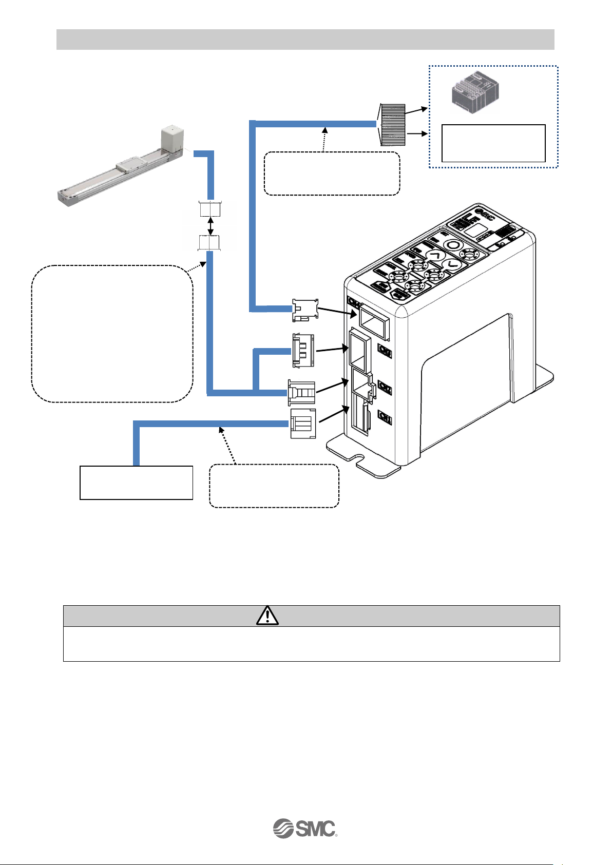
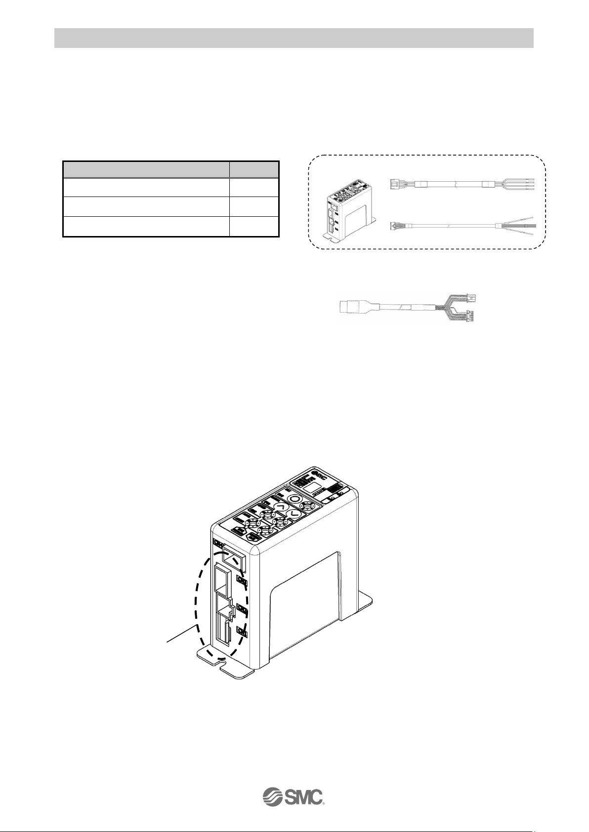
2.2 Product configuration
The product configuration of this controller is as follows.
●
Electric actuator
*1)
*1) These items are included when ordered using the part number for an electric actuator set.
*2) When conformity to UL is required, the electric actuator and controller should be used with a
UL1310 Class 2 power supply.
Warning
Refer to “4. External Connection for wiring”
Refer to “12. Precautions for wiring and cables” when handling the wiring and cables.
To CN4
To CN3
To CN2
To CN1
● Controller
● I/O cable
*1)
Part No: LEC-CK4-□
● Actuator cable
*1)
Part No: LE-CP-□-S
LE-CP-□-B-S
(Standard cable)
LE-CP-□
LE-CP-□-B
(Robotic type cable)
Controller power supply
24VDC
PLC
*3)*4)
Input / output signal
power supply
24 VDC
● Power supply cable
Part No: LEC-CK1-1
Page 9
- 8 -
No.JXC※-OMU0030-A
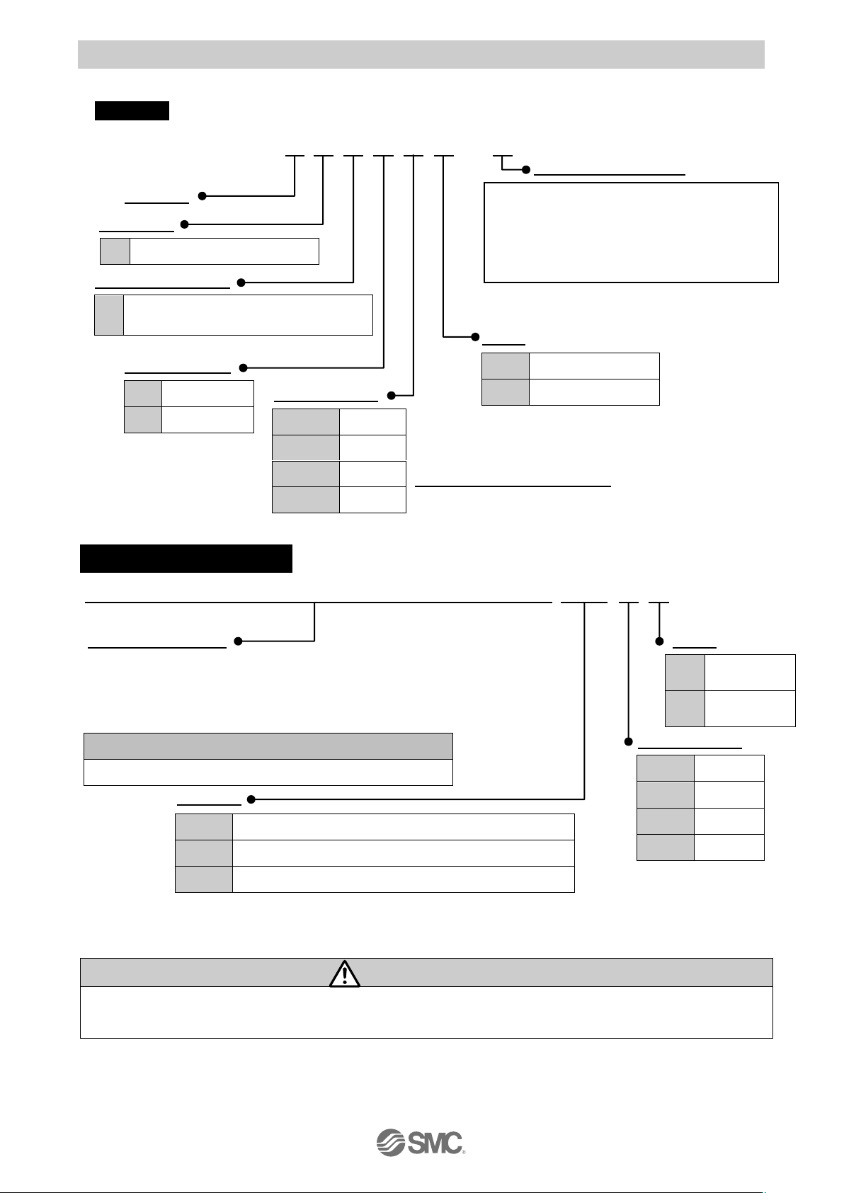
2.3 How to Order
The part number construction for this product is as follows:
Controller
LECP2 N□□-□
Electric actuator model
Controller
Compatible
Number of step data
Option
Parallel I/O type
I/O cable length
1.5 m power cable is included
Electric actuator+Controller
LEMB25UT- 500B-R12 N □□
Electric actuator type
Option
Compile the product number while referring to the How to order section
in the electric actuator catalogue. Please refer to the table below for the
corresponding electric actuator.
I/O cable length
*1)
Controller
*1) An I/O cable cannot be specified for the electric actuator without a controller.
The LECP6 series I/O cable cannot be used because the specifications are different.
Caution
Single controllers are also shipped after setting the electric actuator specification parameters.
Check that the combination of the controller and the electric actuator is correct before use.
Example: LEMB25T-500B-R12N1D
Specify “LEMB25UT-500”
(Enter from the electric actuator part
number “LE” to “stroke / rotating angle”)
P
Step motor (Servo DC24V)
2
12 intermediate points and 2 stroke
end points (Programless)
N
NPN type
P
PNP type
Nil
None
1
1.5m
3
3m
5
5m
Applicable electric actuators
Electric actuator / Low profile slider type:LEM Series
Nill
No controller
*
1)
2N
Programless controller with stroke study (NPN)
2P
Programless controller with stroke study (PNP)
Nil
None
1
1.5m
3
3m 5 5m
Nil
Screw mounting
D
DIN rail mounting
Nil
Screw
mounting
D
DIN rail
mounting
Page 10
- 9 -
No.JXC※-OMU0030-A
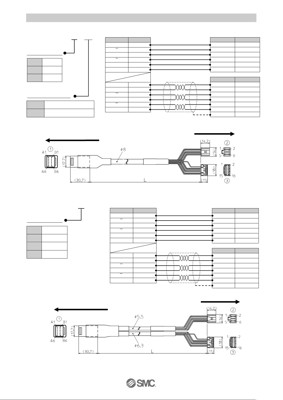
2.4 Option (1) Actuator cable (5m or less)
LE-CP-□-□
Cable length (L)
U Actuator cable type
Electric actuator side
(2) Actuator cable (8-20m)
L E - C P - □
Cable length (L)
*1) Produced upon receipt of order.
Only Robotic type cable can be
selected.
Electric actuator side
Controller side
8
8m
*1)
A
10m
*1)
B
15m
*1)
C
20m
*1)
Controller side
Cable color
Terminal no.
Brown
2
Red
1
Orenge
6
Yellow
5
Green
3
Blue 4 Cable color
Terminal no.
Brown
12
Black
13
Red 7 Black
6
Orange
9
Black 8 - 3 signal
Terminal no.
A
B-1 A A-1 B B-2 B A-2
COM-A / COM
B-3
COM-B / -
A-3 Vcc
B-4
GND
A-4 A B-5 A A-5 B B-6 B A-6
Cable color
Terminal no
Brown
2
Red
1
Orange
6
Yellow
5
Green
3
Bule
4
Cable color
Terminal no
Brown
12
Black
13
Red
7
Black
6
Orenge
9
Black
8
-
3
Shield
① ② ③
signal
Terminal no.
A
B-1
A
A-1
B
B-2
B
A-2
COM-A / COM
B-3
COM-B / -
A-3
Vcc
B-4
GND
A-4
A
B-5
A
A-5
B
B-6
B
A-6
Shield
①
②
③
Nil
Robotic type cable
S
Standard cable
1
1.5m
3
3m
5
5m
Page 11
- 10 -
No.JXC※-OMU0030-A
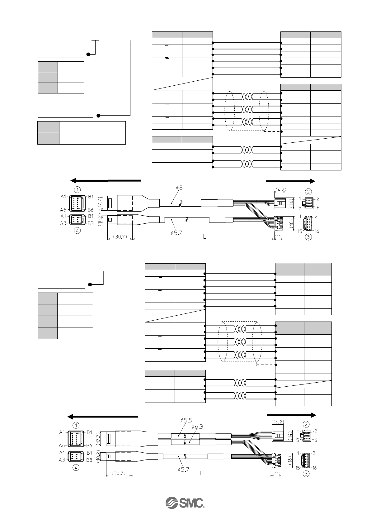
(3) Actuator cable for with lock and sensor (5m or less)
LE-CP-□-B-□
Cable length (L)
Actuator cable type
Electric actuator side
(4) Actuator cable for with lock and sensor (8-20m)
L E - C P - □ - B
Cable length (L)
*1) Produced upon receipt of order.
Only Robotic type cable can
be selected.
Controller side
1
1.5m
3
3m
5
5m
signal
Terminal no.
A
B-1
A
A-1
B
B-2
B
A-2
COM-A / COM
B-3
COM-B / -
A-3
Vcc
B-4
GND
A-4
A
B-5
A
A-5
B
B-6
B
A-6
Cable color
Terminal no.
Brown
2
Red
1
Orange
6
Yellow
5
Green
3
Blue
4
Cable color
Terminal no.
Brown
12
Black
13
Red
7
Black
6
Orange
9
Black
8
-
3
Red 4 Black
5
Brown
1
Blue
2
Shield
①
② ④ ③
signal
Terminal no
A
B-1 A A-1
B
B-2
B
A-2
COM-A / COM
B-3
COM-B / -
A-3 Vcc
B-4
GND
A-4 A B-5 A A-5 B B-6 B A-6
Cable color
Terminal
no
Brown
2
Red
1
Orange
6
Yellow
5
Green
3
Blue 4
Cable color
Terminal
no
Brown
12
Black
13
Red
7
Block
6
Orange
9
Black
8
-
3 Red 4 Black
5
Shield
①
②
signal
Terminal no
Lock
(+)
B-1
Lock
(-)
A-1
Sensor
(+)
B-3
Sensor
(-)
A-3
④
③
8
8m *
1
)
A
10m *
1
)
B
15m *
1
)
C
20m
*1
)
Electric actuator side
Controller side
Nil
Robotic type cable
S
Standard cable
signal
Terminal no.
Lock
(+)
B-1
Lock
(-)
A-1
Sensor
(+)
B-3
Sensor
(-)
A-3
Page 12
- 11 -
No.JXC※-OMU0030-A
2.5 Startup Procedures
Be sure to check the procedure below before use.
(1) Confirmation of the package content
After unpacking everything, check the description on the label to identify the controller and the number
of accessories. If any parts are missing or damaged, please contact your distributor.
*1) Included in the package only when the I/O
cable length is specified.
【
Option
】
●
Actuator cable
(2) Installation
Please refer to “3.4 How to install”
(3) Wiring and connection
Connect cables, etc. to the connector (CN1 to CN4) of the controller.
Please refer to “4 External Wiring Diagram” for the wiring of the connectors.
Connector
Item
Quantity
Controller
(LECP2□□-□)
1 unit
Power supply cable
(LEC-CK1-1)
1 piece
I/O cable
(LEC-CK4-□)
1 piece
Actuator cable
Controller Power supply cable
I/O cable
Page 13
- 12 -
No.JXC※-OMU0030-A
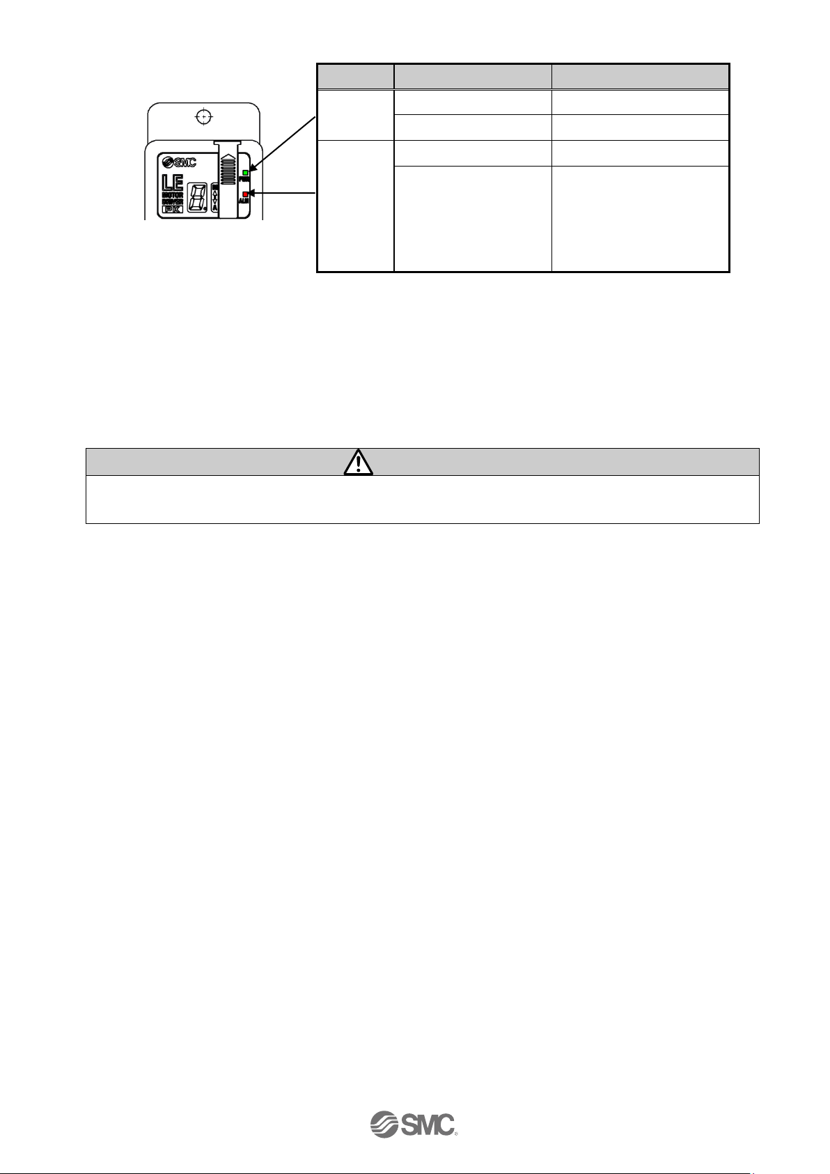
(4) Power ON alarm (error)
Supply 24 VDC power supply.
Controller
Under normal conditions, the LED [PWR] on the front of the controller changes from a flashing to a
solid light.
The servo will be turned ON if the conditions are normal.
When the LED [ALM] on the front of the controller is ON red, an alarm is generated.
When the power is supplied to the controller just after it is delivered, ALM LED of the controller flashes
in red because Stroke study is not completed.
Therefore, in this case, it is necessary to perform Stroke study.
Caution
If an alarm is generated, check the content of the alarm using the 7-segment LED on the controller or
I/O output, and eliminate the cause while referring to section
“11. Alarm Detection”
.
(5) Stroke study
The stroke study is performed with the buttons and the switches on the controller.
A stroke study of the controller must be performed immediately after purchase or adjustment of the
electric actuator stopper.
Refer to
“7.1(3) Stroke study”
for details.
(6) Registering of the stopping position
The stopping position, speed and acceleration and deceleration are registered with the buttons and
switches on the controller. Refer to
“7.1(7) Registering of the intermediate position”
for details.
(7) Operation check
The operation of the electric actuator is tested by the test run.
The test run is performed with the buttons and the switches on the controller.
Refer to
“7.1(4) Test run”
for details.
(8) The operation of the electric actuator
Change the mode to auto mode using the controller switch. Electric actuator can be operated by
external equipment (PLC, etc.). Refer to
“9. Operation instruction”
for details.
Function
LED turns on
Status
PWR
Green LED is ON
Servo is turned on
Green LED is flashing
Servo is turned off
ALARM
Red LED is ON
Alarm is generated
Red LED is flashing
Stroke study is not
completed
(Only when the power is
supplied for the first time
after the purchase)
Page 14

- 13 -
No.JXC※-OMU0030-A
3. Product Specifications
3.1 Basic specifications
The basic specifications of this controller are as follows:
Item
Specifications
Compatible motor
Unipolar winding method 2-Phase HB step motor
Power supply
*1)
Power voltage: 24 VDC +/-10%
*2)
When conformity to UL is required, use UL1310 compliant Class 2
power supply unit for direct current.
Parallel input
6 inputs (photo-coupler isolation)
Parallel output
6 outputs (photo-coupler isolation)
Stop points
Stroke ends 2 points (Position number 1 and 2),Intermediate position
12 points (Position number 3 to14(E))
(Stroke end (Position number 1 and 2) cannot be changed)
Compatible encoder
Incremental A / B phase (800 pulse / rotation)
Memory
EEPROM
LED indicator
2 of LED’s (green and red)
7-segment LED display
*3)
1 digit, 7-segment display (red)
Figures are expressed in hexadecimal (10 to 15 in decimal number are
expressed as A to F)
Lock control
Forced-lock release terminal (Applicable to non -magnetizing lock.)
Cable length
I/O cable: 5m or less
Actuator cable: 20m or less
Cooling system
Natural air cooling
Operating temperature
range
0 to 40oC (No freezing)
Operating humidity range
90%RH or less (No condensation)
Storage temperature
-10 to 60oC (No freezing)
Storage humidity range
90%RH or less (No condensation)
Insulation resistance
Between external terminals and case
Mass
130 g (screw mount type)
150 g (DIN rail mount type)
*1) Do not use the inrush current suppression type power supply for the controller power (24VDC).
*2) The power consumption changes depending on the electric actuator model.
Please refer to the specifications of the electric actuator for more details.
*3) "10" to "15" in decimal number are displayed as follows in the 7-segment LED.
Decimal display 10 11 12 13 14 15
Hexadecimal display A b c d E F
Page 15
- 14 -
No.JXC※-OMU0030-A
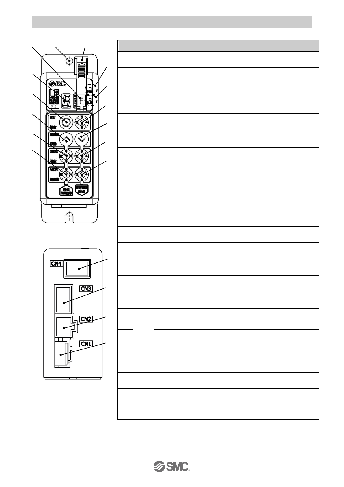
3.2 Parts description
The detailed descriptions of each part are as follows:
No.
Display
Description
Details
(a)
PWR
Power
supply LED
Power supply ON / Servo ON: Green turns on
Power supply ON / Servo OFF: Green flashes
(b)
ALM
Alarm LED
Power supply ON / With alarm: Red flashes
Power supply ON / Un-performing of Stroke study
:Flashes in red
Power supply ON / Parameter setting: Red flashes
(c)
―
Cover
Protection of the mode switch changing.
(Close the cover after changing swich).
(d)
―
FG
Frame ground
(Tighten the bolt with the nut when mounting the
controller. Connect the grounding wire.)
(e)
―
Mode switch
Swich the mode between manual and auto.
(f)
―
7-segment
LED
Auto mode / Without alarm:
Indicates the position number which is command
by ON/OFF of IN0 to IN3 of the CN4 parallel I/O.
(During command operation: Flashing / Instruction
command completed: ON)
Auto mode / With alarm:
Indicates Alarm Group.
Manual mode: Indicates that content may vary
depending on the operating function.
(g)
SET
Set button
Determines the settings and gives a command to
operate in manual mode.
(h)
―
Position
switch
Assigns the position to drive (1 to 14).
(i)
MAN
UAL
Forward
button
Performs forward jog and inching.
(j)
Reverse
button
Performs reverse jog and inching.
(k)
SPEED
Forward
speed switch
16 forward speeds are available.
*1)
(l)
Reverse
speed switch
16 reverse speeds are available.
*1)
(m)
ACCEL
Forward
acceleration
switch
16 forward acceleration steps are available.
*1)
(n)
Reverse
acceleration
switch
16 reverse acceleration steps are available.
*1)
(o)
CN1
Power
supply
connector
Connect the power supply cable.
(p)
CN2
Motor driving
connector
Connect motor connector of actuator cable.
(q)
CN3
Encoder
connector
Connect encoder connector of actuator cable.
(r)
CN4
I/O
connector
Connect I/O cable.
*1) The Set value of speed and acceleration are set for r
everse
and f
orward
directions.
The set value will be reflected in the operation of all position numbers.
(e) (d) (c)
(a)
(b)
(h)
(j)
(l)
(n)
(f)
(g)
(i)
(k)
(m)
(r)
(q)
(p)
(o)
Page 16
- 15 -
No.JXC※-OMU0030-A
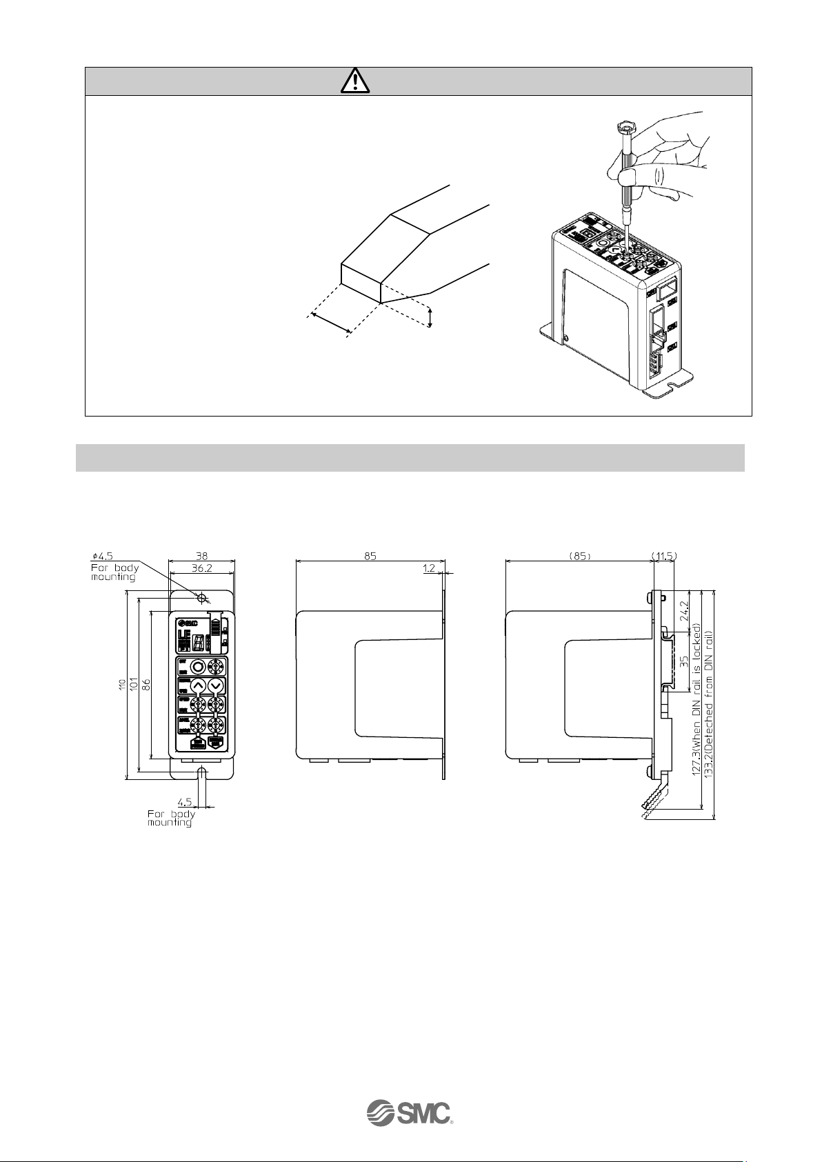
Caution
Use a flat blade watchmaker's screwdriver of the size shown below when
changing position switch (h) and the set value of the speed / acceleration
switches (k) to(n)
<Size>
End width L:2.0 to 2.4 [mm]
End thickness W:0.5 to 0.6 [mm]
Magnified view of the end of the
flat blade screwdriver
3.3 Outside dimension diagramm
The outside view of this product is as shown in the diagram below:
(1) Screw mount type (2) DIN rail mount type
(LECP2□□-□) (LECP2□□D-□)
L
W
Page 17
- 16 -
No.JXC※-OMU0030-A
3.4 How to install
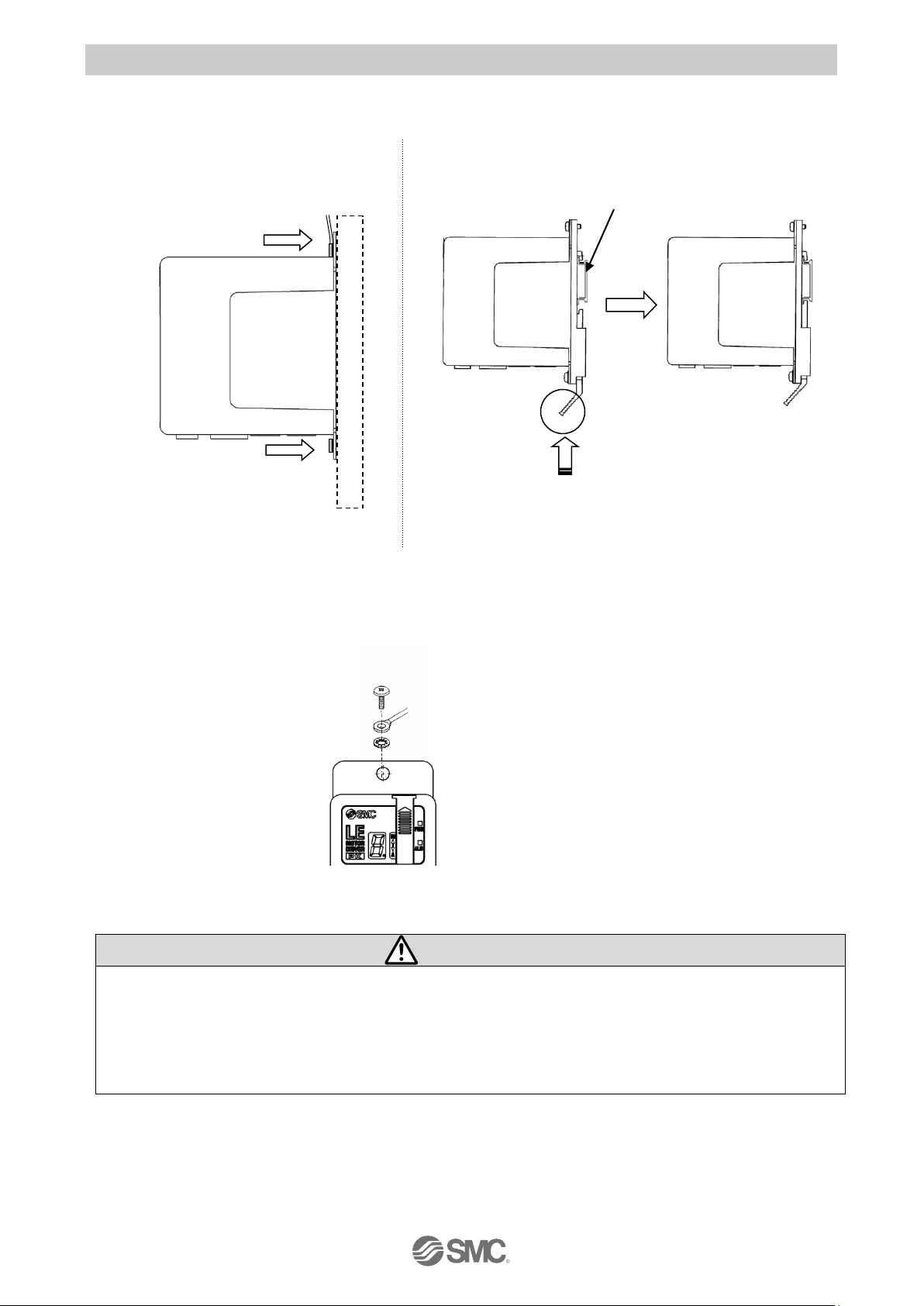
(1) How to install
The followings are the descriptions on how to install each type:
1) Screw mounting (LECP2□□-□) 2) DIN rail mounting (LECP2□□D-□)
(Installation with two M4 screws)
(2) Ground wire connection
Place the grounding cable with crimping terminal and toothed washer as shown below and tighten the
screw.
Controller
Caution
The M4 screw, cable with crimping terminal, and toothed washer should be obtained separately.
Ground the controller to shield it from electric noise.
Controller attaching hole (Installation position of grounding cable) and SG (Signal ground) are
connected in the controller.
Please do not ground the controller when using it in the plus earth environment.
Mounting
direction
Mounting
direction
Ground
wire
DIN rail
Hook the controller on the DIN rail
and press the lever of section A in
the arrow direction to lock it.
A
M4 screw
Cable with crimping terminal
Toothed washer
Page 18
- 17 -
No.JXC※-OMU0030-A
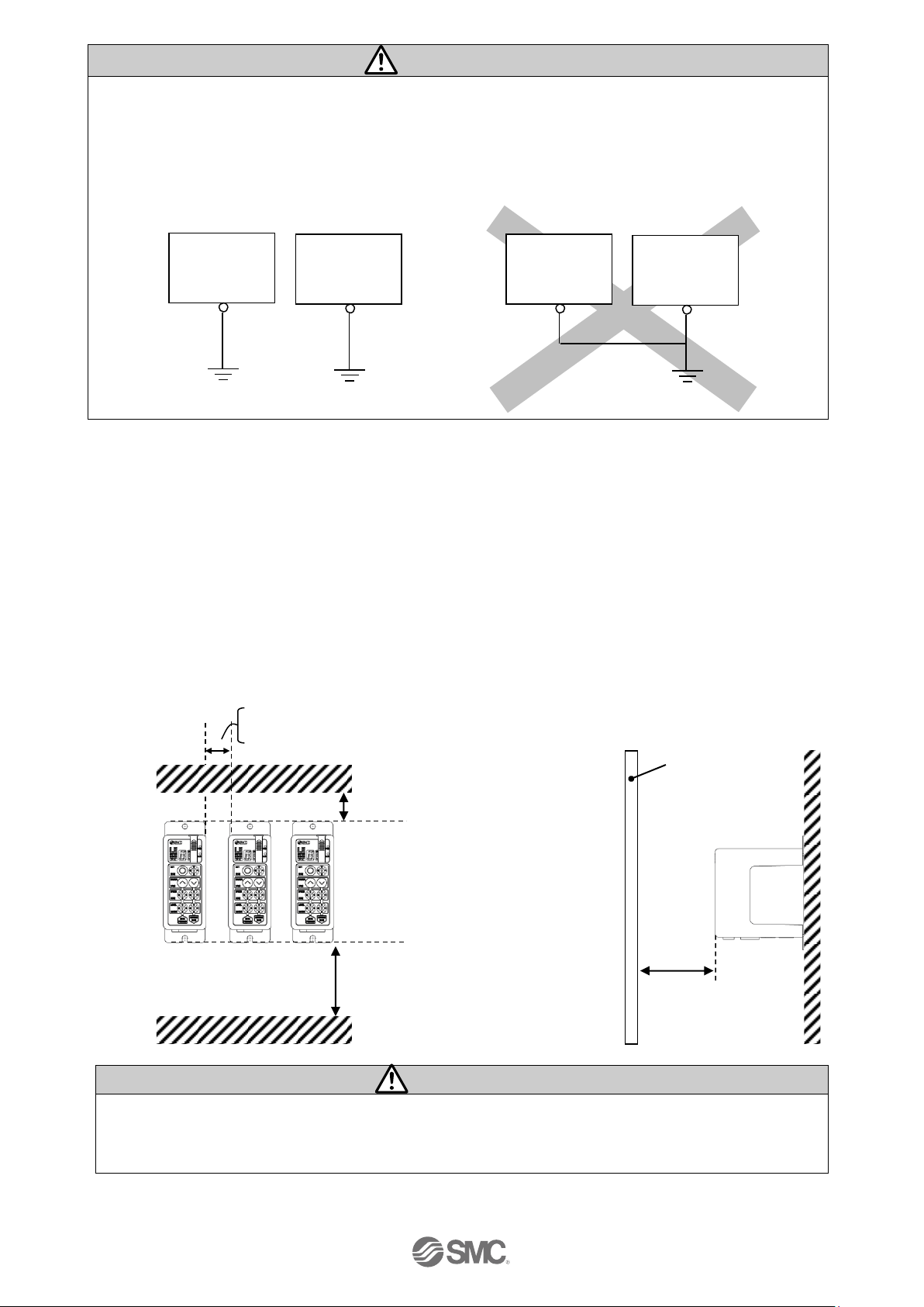
Caution
The earthling should be the dedicated grounding point. It should be a functional ground with less
than 100 Ω resistance.
The cross section of the grounding wire should be greater than 2mm2.
The ground point should be near this controller to make the wire length short.
The controller case mounting is connected to 0 V of the power supply.
Recommended Functional grounding Not Recommended grounding
(3) Installation location
Select the size and the installation style so that the ambient temperature around the controller is 40
o
C or less.
Mount the controller vertically on a wall with the space allowed as shown in Fig.1.
As shown in Fig.2, establish the construction so that the connectors can be connected and
disconnected.
Enough space must be allowed around the controller so that the operating temperature of the
controller stays within the specification range.
Avoid mounting the controller near a vibration source, such as a large electromagnetic contactor or
circuit fuse breaker on the same panel.
Fig.1 Fig.2
Caution
If the mounting surface of the controller is distorted or not flat, excessive force may be applied to the
housing, etc. causing malfunction.
Mount this product on a plane flat surface.
controller
30 mm or more
60 mm or more
60 mm or more
Controller
Door (Lid)
0 mm or more: Body size 16 or less *Only the LEH series apply to all size
10 mm or more: Body size 25 or more *Except for LEH Series
Controller
Other
device
Controller
Other
device
Page 19
- 18 -
No.JXC※-OMU0030-A
PLC, etc
(The PLC, etc. should be obtained separately.)
Controller input power supply 24 VDC
(The 24 VDC power supply and the power cable
should be obtained separately.)
4. External Wiring Diagram
Examples of standard wiring are shown for each connector (CN1 to CN4) of the controller.
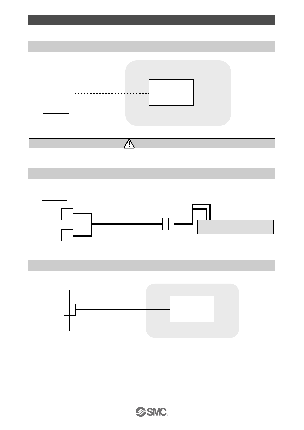
4.1 CN1: Power supply cable
Controller
CN1 Power supply cable
Please refer to “5. CN1: Power supply cable” for how to wire the CN1 connector.
Caution
Do not use the inrush current suppression type power supply for the controller power (24VDC).
4.2 CN2: Motor power connector and CN3: Encoder connector
Connect the controller and the electric actuator with the actuator cable (LE-CP-□-□).
Controller
CN3 Actuator cable Electric actuator
CN2
4.3 CN4: Parallel I/O connector
Controller
I/O cable
CN4
Please refer to "6.4 Parallel I/O Wiring Example" for how to wire the CN4 connector.
Please refer to "6.3 The parallel I/O signal is detailed" for details of each signal of parallel I/O.
Motor
Page 20
- 19 -
No.JXC※-OMU0030-A
5. CN1: Power supply cable
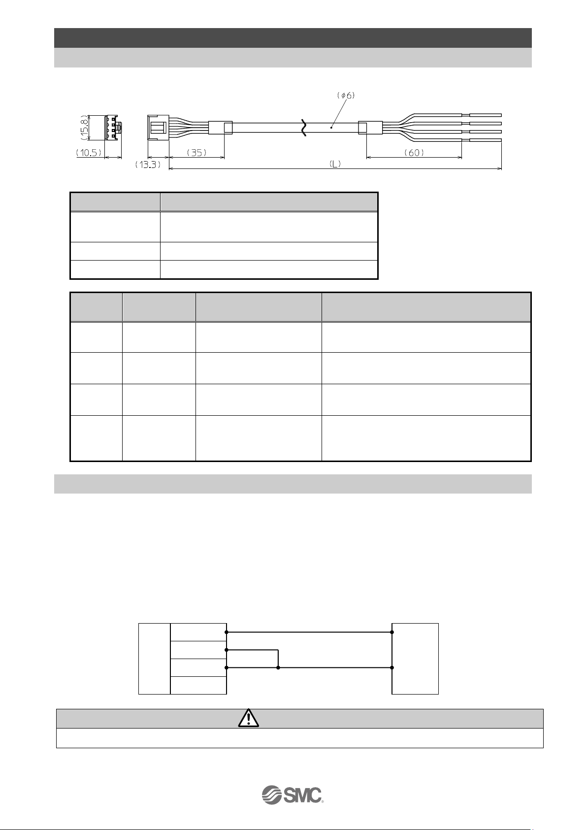
5.1 Power supply cable specifications
Included power supply cable specification is shown below.
Item
Specifications
Connector
Manufacturer : J.S.T. Mfg. Co.,Ltd.
Product number : VHR-4N
Conductor size
AWG20
Length (L)
LEC-CK1-1:1.5m only
Terminal
Color of
covered wire
Function
Functional explanation
0V
Blue
Common power supply (-)
Negative common power for M24V, C24V,
and BK RLS.
M24V
White
Power supply of motor (+)
Positive power for the motor to be supplied
via the controller.
C24V
Brown
Control power supply (+)
Positive control power to be supplied to the
controller.
BK RLS
Black
Unlocking (+)
Positive power for lock release.
(Connected to the M24V in the controller
internal circuit.)
5.2 Wiring of power supply cable
Referring to (1) to (4), connect the power supply cable included in accessories to the controller input
power supply 24 VDC and insert it to the controller CN1 power supply connector.
(1) Wiring of the power supply
Connect the positive side (+) of the controller input power supply 24 VDC to the C24V and M24V
terminals of the power supply cable, and connect the negative side (-) to the 0V terminal.
Power supply cable Controller input power supply
Caution
Do not use the inrush current suppression type power supply for the controller power (24VDC).
0V
24V
0V
M24V
C24V
BK RLS
Page 21
- 20 -
No.JXC※-OMU0030-A
(2) Wiring of the lock release
Install an unlocking switch for adjustment or recovery during an emergency of the electric actuator with
lock. The switch (24 VDC, Contact capacity: 0.5A or more) should be obtained separately.
One terminal of the lock release switch should be connected to the 24 VDC power supply and the
other should be connected to the BK RLS terminal. When this is switched on, the lock will be released
forcibly.
Power supply cable Controller input power supply
Switch for forced unlocking
Caution
If the electric actuator is a non-lock type, it is not necessary to wire the BK RLS terminal.
Do not supply power to the BK RLS (lock release) during normal operation.
The 24 VDC supply to the BK RLS (lock release) is only required for the adjustment and the recovery
in the emergency.
- STOP command (CN4 14pin STOP) is turned ON and Servo is turned OFF.
- When the control power supply (C24V) is shut off.
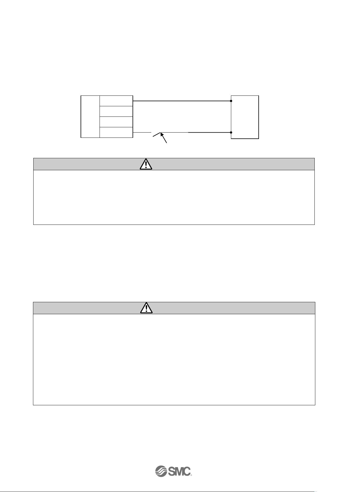
(3) Stop the power supply for the motor
If it is necessary to shut off the power supply for the motor from outside, connect the relay between the
input power supply for the controller 24 VDC and the power supply plug for the controller M24V.
(Refer to the wiring diagram in the next page.)
The motor power supply should be shut off after the STOP command (CN4 14pin STOP) is turned ON.
Refer to “6.3 Details of parallel input / output signal and cable” for the STOP command
Warning
- Do not perform a return to origin position when the the power supply for the motor (M24V) is off. The
controller cannot recognize the correct origin if a return to origin instruction is made with the motor
drive power (M24V) disconnected.
- If the M24V is off during electric actuator operation, there will be an additional delay experienced
before it stops (the stop distance will be extended) due to inertia of the work piece or regenerated
energy. When the M24V is turned off, and the STOP command is turned ON (CN4 14pin STOP)
simultaneously the time to stop can be shortened.
- If the motor drive power is off during a vertical stop, the table may drop due to lock response.
- BK RLS is internally connected to the M24V inside the controller, so do not apply 24 VDC to the BK
RLS terminal when the M24V is off.
0V
M24V
C24V
BK RLS
0V
24V
Page 22

- 21 -
No.JXC※-OMU0030-A
(Circuit example: The figure below shows the stopped state.)
Power supply cable(the 1st controller) Controller input power supply
Power supply cable(the 2nd controller) Controller input power supply
Power supply cable(the 3rd controller) Controller input power supply
24 VDC
Ry
0 V
STOP
switch
Surge suppressor
Reset switch for stop
Ry
0V
24V
Ry
0V
M24V
C24V
BK RLS
Ry
0V
M24V
C24V
BK RLS
0V
24V
Ry
0V
M24V
C24V
BK RLS
0V
24V
Page 23

- 22 -
No.JXC※-OMU0030-A
6. CN4: Parallel l/O Connector
6.1 Parallel I/O specifications
■ Input specifications ■Output specifications
6.2 Parallel I/O type (NPN / PNP type)
There are two types of parallel I/O for this controller: NPN type and PNP type.
(1) Parallel I/O input circuit (same for both NPN and PNP type)
●
NPN type (LECP2N
□□-□)
●
PNP type (LECP2P
□□-□)
(2) Parallel I/O output circuit
●
NPN type (LECP2N
□□-□)
● PNP type (LECP2P□□-□)
No
Item
Specification
1
Output circuit
Internal circuit and photo
coupler Isolation
2
Number of outputs
6 outputs
3
Max. voltage
between terminal
30 VDC
4
Max. output current
10mA supply / sink
5
Saturation voltage
2.0V (Max.)
No
Item
Specification
1
Input circuit
Internal circuit and photo
coupler isolation
2
Number of
inputs
6 inputs
3
Voltage
24 VDC +/- 10%
4
Input current at
ON
3.5mA +/- 20%
(at 24 VDC)
5
Input current /
voltage at OFF
Current 1.5 mA or less
Voltage 11V or less
(a)
(b)
Inside of the controller
(a)
「COM+」〈1〉
(b)
IN0〈9〉 to STOP〈14〉
(a)
「COM-」〈2〉
(b)
IN0〈9〉 to STOP〈14〉
Outside
OUT0〈3〉
~ALARM〈8〉
「COM-」 〈2〉
「COM+」 〈1〉
Outside
Outside
1kΩ
10Ω
10Ω
OUT0〈3〉
~ALARM〈8〉
6.8kΩ
Inside of the controller
Inside of the controller
Page 24

- 23 -
No.JXC※-OMU0030-A
6.3 Details of parallel input / output signal and cable (1) Parallel I/O cable(LEC-CK4-□)
Controller side PLC side
Item
Specification
Connector
Manufacturer : J.S.T. Mfg.Co.,Ltd.
Product number : PADP-14V-1-S
Conductor size
AWG26
Length (L)
The suffix of the part number (1,3,5) specifies the length.
LEC-CK4-1: 1.5m LEC-CK4-3: 3m LEC-CK4-5: 5m
(2) Derails of input / Output signal
Terminal
No.
Insulation
color
Dot
Mark
Dot color
Function
Contents
1
Light
brown
■
Black
COM+
Connect the 24 V side of the power supply (24 VDC) for input /
output signal.
2
Light
brown
■
Red
COM-
Connect the 0 V side of the power supply (24 VDC) for input /
output signal.
3
Yellow
■
Black
OUT0
Operation completion output
(Output with the combination of OUT0 to OUT3)
*1)
・When the return to origin is performed:
OUT0 output is turned on only when the return to origin is
commanded by IN0.
OUT1 output is turned on only when thereturn to origin is
commanded by IN1.
・Command the target position (end side or motor end):
OUT output equal to the IN input is turned on at the
position several mm away from the end.
・Target position is intermediate position of the stroke:
After stopping at the target position, OUT output equal to
the IN input is turned on.
Example) Output the operation completion of position No. 3
OUT3
OUT2
OUT1
OUT0
OFF
OFF
ON
ON
After the external stopper of the electric actuator is adjusted,
when the operation to motor side or end side is commanded
without the stroke study, the electric actuator might not be
reached to the stroke ends. In that case, the OUT output
state is kept, and the alarm is not generated. Perform the
stroke study and register all of the intermediate positions
after adjusting the external stopper.
4
Yellow
■
Red
OUT1
5
Light
green
■
Black
OUT2
6
Light
green
■
Red
OUT3
7
Grey
■
Black
BUSY
BUSY signal (Turning ON during operating)
Page 25

- 24 -
No.JXC※-OMU0030-A
8
Grey
■
Red
ALAR
M
ALARM signal N.C.
(Turned off when an alarm is generated or servo is turned off.
The ALARM output is turned off when STOP is input and the
electric actuator has stopped).
9
White
■
Black
IN0
・Inputting the intermediate target position command
(Input the binary position number by combining IN0 to
IN3.
*1)
)
Example) Command to move to position number 5.
IN3
IN2
IN1
IN0
OFF
ON
OFF
ON
・End start command input (only IN0 is ON)
・Motor start command input (only IN1 is ON)
Return to origin
When power is applied to the LECP2 in which stroke
study has already been performed, the electric actuator
return to origin in the specified direction at low speed by
turning on the target position command (motor end or
end side).
When the power is applied to the LECP2 in which stroke
study is performed, the input of target position command
(IN0, IN1) is disabled.
10
White
■
Red
IN1
11
Light
brown
■
■
Black
IN2
12
Light
brown
■
■
Red
IN3
13
Yellow
■
■
Black
RESE
T
Operation interruption or alarm reset
In action: The speed is reduced from the point where the
signal is input until the electric actuator stops.
(Servo stays ON)
Alarm occurring: Alarm reset
14
Yellow
■
Red
STOP
Stop command (Immediate deceleration to turn off servo)
Parallel I/O signal is valid in auto mode. (STOP signal is valid in auto mode and manual mode.)
During manual mode, input signals except STOP isinvalid. All output signals are OFF.
During manual mode testing, output signals are valid (input signals other than STOP are invalid)
*1) The following table shows the relation of the positon number and the combination of IN0 to IN3 or
OUT0 to OUT3.
○:
OFF ●:ON ○:OFF ●:ON
Position
number
IN3
IN2
IN1
IN0
Position
number
OUT3
OUT2
OUT1
OUT0
1
(End side)
○ ○ ○
●
1
(End side)
○ ○ ○
●
2
(Motor side)
○ ○ ●
○
2
(Motor side)
○ ○ ●
○ 3 ○ ○ ●
●
3
○ ○ ●
●
4
○ ● ○
○
4
○ ● ○
○
5
○ ● ○
●
5
○ ● ○
● 6 ○ ● ●
○
6
○ ● ●
○
7
○ ● ●
●
7
○ ● ●
●
8
● ○ ○
○
8
● ○ ○
○ 9 ● ○ ○
●
9
● ○ ○
●
10 (A)
● ○ ●
○
10 (A)
● ○ ●
○
11 (b)
● ○ ●
●
11 (b)
● ○ ●
●
12 (c)
● ● ○
○
12 (c)
● ● ○
○
13 (d)
● ● ○
●
13 (d)
● ● ○
●
14 (E)
● ● ●
○
14 (E)
● ● ●
○
Page 26

- 25 -
No.JXC※-OMU0030-A
(3) The change of I/O output signal
The change of I/O output signal under the condition of controller at auto mode.
Condition of the controller
Output signal
OUT0
OUT1
OUT2
OUT3
BUSY
ALARM
Right after supplying power
OFF
OFF
OFF
OFF
OFF
OFF
After supplying power and at the stop
before return to origin.
OFF
OFF
OFF
OFF
OFF
ON
During the return to origin,
positioning, and pushing operation.
OFF
OFF
OFF
OFF
ON
ON
When return to origin is completed.
*1) *1)
OFF
OFF
OFF
ON
When positioning operation or
pushing operation is completed.
*2) *2) *2) *2)
OFF
ON
Stopped by RESET command
OFF
OFF
OFF
OFF
OFF
ON
Stopped by STOP command
*3)
*3)
*3)
*3)
OFF
OFF
When alarm is generated
OFF
*4) *4) *4)
OFF
OFF
*1) Return to origin command is given by the IN0 ON: OUT0 is ON, OUT1-OUT3 are OFF.
Return to origin command is given by the IN1 ON: OUT1 is ON, OUT0 and OUT2,OUT3 are OFF.
*2) The ON / OFF status of OUT0 to OUT3 is different depending on the commanded position number.
*3) Not fixed. Varies depending on conditions. (When STOP command is given, OUT0 to OUT3 are
OFF. When an alarm is generated, the alarm group is output to the OUT1 to OUT3.)
*4) ON, OFF of OUT1 to OUT3 depends on the alarm group.
There is no servo ON signal with this controller. The servo turns off when conditions to turn off the
servo are satisfied. Refer to “8.4 Servo ON” for details.
Caution
・IN0 to IN3 input during the switching from manual mode to auto mode are invalid. IN0 to IN3 become
valid after the auto mode is set up.
・Output signal are not output from parallel I/O right after switching from manual mode to auto mode.
Output signal will be output from parallel I/O after inputting the next command.
・Output from I/O is not made if switching from auto mode to manual mode.
Page 27

- 26 -
No.JXC※-OMU0030-A
6.4 Parallel I/O Wiring Example
When you connect a PLC, etc. to the CN4 parallel I/O connector, please use the I/O cable
(LEC-CK4-□).
The wiring should be changed depending on the type of the parallel I/O (NPN or PNP).
Please wire referring to the following diagram.
● NPN type ● PNP type
Caution
The 24 VDC controller power supply for CN1 and the 24 VDC I/O power supply for CN4 should be
separated.
Load
Load
Load
Load
I/O signal power
24VDC
ALARM
BUSY
OUT3
OUT2
OUT1
OUT0
STOP
RESET
IN3
IN2
IN1
IN0
COM-
COM+
Load
Load
Load
Load
Load
Load
I/O signal power
24VDC
ALARM
BUSY
OUT3
OUT2
OUT1
OUT0
STOP
RESET
IN3
IN2
IN1
IN0
COM-
COM+
Load
Load
Page 28

- 27 -
No.JXC※-OMU0030-A
7. Setting method
It is necessary to set the stop position and operation method using the controller in order to move the
electric actuator to the specified position. Set data is stored in the memory in the controller.
In manual mode, operation of the electric actuator is based on position
registration parameters. In auto mode, the electric actuator operation is
based on setting of external equipment via CN4 parallel I/O.
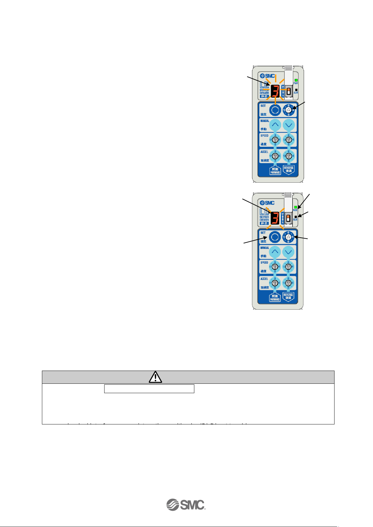
1. Switching the mode
The mode is switched by moving Mode switch (e).
Upper part of the right figure (M) : Manual mode
Lower part of the right figure (A) : Auto mode
The display at auto mode:
"-" or the position number that is commanded through IN0 to
IN3 of CN4 parallel I/O is displayed in 7-segment LED(f).
・When driving : Displayed in flashing state.
・When driving is completed: Displayed in on state.
When the button is pressed or rotary switch is rotated during
auto mode, the 7-segment LED(f) flashes for a specified
period of time to indicate that inputting by the button or rotary
switch is disabled (locked).
Caution
Close the cover (c) after the switching of the mode to avoid unexpected mode changes.
2. Difference according to mode ○: available ×: not available △: Depending on conditions
Manual mode (M)
Auto mode (A)
Register intermediate position
(Step data registration)
○
×
Stroke study
○
×
Setting of Speed and
Acceleration
○
△
(Only in speed adjustment)
*1)
Setting of parameters
○
×
Driving the electric actuator with
using the button on the controller
○
×
Operation of the electric actuator
via CN4 parallel I/O
×
○
Positioning operation
(In LECP2 pushing operation is
not available)
○
○
Test run
○
×
Check the presence of alarm
(Alarm LED(b))
○
○
Check the content of alarm
(7-segment LED (f) display)
○
○
How to release the alarm
Press set button (g)
Turn on RESET or press set button (g)
Servo OFF method
Press Forward button (i)
and Reverse button (j)
simultaneously for 3 sec.
- Turn on STOP
Turn on STOP
*1) Refer to “7.2. Setting of the speed and the acceleration” for details of the adjustment of the
speed in the auto mode.
(f) (e) (c)
(g)
(i)
(a)
(b)
(h)
(j)
Page 29

- 28 -
No.JXC※-OMU0030-A
7.1 Setting procedure
Follow the procedure below for setting.
(1) Supply of power
↓
(2) Changes to Manual mode
↓
(3) Stroke study
↓ (7) Intermediate position setting
(4) Test run
↓
(5) Setting of speed / acceleration
↓
(6) Setting completed
(1) Supply of power
Apply 24 VDC to the power supply for the power line and the signal line. After applying the power,
confirm that the Power supply LED (a) lights green (= Servo ON). Refer to “8.4 Servo ON” if the
power supply LED (a) flashes green (= Servo OFF).
When alarm LED (b) lights up, refer to “11. Alarm Detection”.
(After supplying power, it may take approximately 10 seconds (max. 20 sec.) until ALARM is output
depending on the electric actuator positions.)
(2) Changes to Manual mode
Switch the controller mode switch (e) to manual mode (M side). In manual mode, the 7-segment LED
(f) indicates the value of the position switch (h) with high speed flashing.
(3) Stroke study
Electric actuator end and motor end can be automatically detected and registered to the controller.
Be sure to perform a "Stroke study" before initial operation and when the operating stroke range is
changed, due to the replacement of the electric actuator or the installation of an external stopper.
*When power is supplied to the controller just after it is delivered, LED [ALM] flashes in red. This
indicates that stroke study is not yet performed. Please perform Stroke study.
After the external stopper of the electric actuator is adjusted, when operation the operation to motor
side or end side is commanded without the stroke study, the electric actuator might not be reached to
the stroke ends.
After the external stopper of the electric actuator is adjusted, when the driving to motor side or end
side is commanded without the stroke study, the electric actuator might hit the stroke ends or external
stopper, and the electric actuator might be broken.
(f) (e) (c)
(g)
(a)
(b)
(h)
Page 30

- 29 -
No.JXC※-OMU0030-A
1) Movement of Storoke study
When “Stroke study” is performed, the electric actuator drives to the end side and the motor side,
and detec the stroke ends of electric actuator.
The positions of stroke ends are registered in the controller by this operation.
Stroke end is detected
Table
Motor side Motor side End side
Table
Motor side End side
2) Procedure of Stroke study
1. Switch to manual mode (M side) by Mode switch (e).
2. Rotate Position switch (h) to “15”.
LED(f) displays “F” with flashing.
3. Push Set button (g) and keeps pushing 3 seconds or more.
Stroke study is started.
4. When the display "F" in LED (f) is changed from flashing state to
solid light state, Stroke study is completed.
Caution
During stroke study, all registered intermediate positions are changed.
Register all intermediate positions (position number from 3 to 14(E)) again.
Caution
When the parameter “Reference for rotating
direction” is changed, the driving direction in
“Stroke study” is opposite to above explanation.
Electric actuator
motor
Electric actuator
motor
Electric actuator
motor
Stop position
A few mm
(h)
(f)
(g)
(e)
1. Table moves to motor side of
electric actuator.
2. Table drives to end side of electric
actuator.
3. Table drives a few mm to motor side
and stops. (Completed)
Page 31

- 30 -
No.JXC※-OMU0030-A
(4) Test run
Check the registered positions by operating the electric actuator with
the controller button and switch operation. The test operation
procedure is as follows.
1) Rotate the position switch (h) to the position number to be tested.
2) Confirm that the 7-segment LED (f) flashes at the specified
position number.
3) Press the set button (g).
When the display in LED (f) is changed from flashing state to
no-flashing state, Trial run is completed.
Item
Test operation state
Input of CN4 parallel I/O
Disable
(Valid only for STOP)
Output of CN4 parallel I/O
The output state when switching
to manual mode is kept
The display of 7-segment LED
Before Test run
: The position number flashes
During Test run : “-” flashes.
Reaching the target position
: Position number lit
Adjusting speed and
acceleration
Possible by using (k) to (n)
(5) Setting of Speed and Acceleration
One speed and acceleration can be set for each movement direction (Reverse and Forward) and it is
applied for the operation of all position numbers.
Set the speed and the acceleration by switch (k) to (n) per direction of actuation. The switch can be
set in 16 steps. Actual value depends on the electric actuator. Refer to “10. Initial setting value of
electric actuator (LEM series)” for details of setting the speed and the acceleration. The operation
with the set speed and acceleration can be checked by test run as shown above (4)Test run.
Different speeds and accelerations cannot be individually set for positioning of each position number.
(6) Completion of setting
After set-up is completed, switch to auto mode using the mode switch (e) and perform operation with
PLC. Please confirm “9. Operation instruction” for driving instruction method with PLC.
Caution
Close the cover (c) after the switching of the mode to avoid unexpected mode change.
(f) (e) (c)
(g)
(i)
(k)
(m)
(h)
(j)
(l)
(n)
Page 32
- 31 -
No.JXC※-OMU0030-A
(7) Intermediate position setting
In the manual mode after return to origin, the position can be registered by the following 2 methods.
(A) Position setting by Jog operation and Inching operation.
Method to register the electric actuator slider position by Jog or Inching operation.
The following is an example of registering a position in
position number 3.
1) Switch Position switch (h) to the position number
to register ("3" is in this example).
7-segment LED (f) displays the position number.
The position can not be registered into the position
number "0",”1”,”2” and "F (15)".
2) When PWR LED (a) is ON, push Set button (g).
The electric actuator drives to the originally
registered position in the commanded position
number.
When completing, the display of 7-segment LED
(f) change from flashing state to solid light state.
Then, keep pushing Set button (g) until 7-segment
LED (f) displays with flashing.
The electric actuator stops on the way when Set button (g) is pushed during driving the electric
actuator.
Then, when Set button (g) is pushed again, the electric actuator drives to the originally registered
position.
Caution
● When procedure (2) Changes to Manual mode is performed before the return to origin is not
completed, the driving command is canceled and the electric actuator does not drive. In that
case, perform the return to origin.
● When the electric actuator cannot drive to the originally registered position due to the
(f)
(h)
(f)
(g)
(a)
(b)
(h)
Page 33

- 32 -
No.JXC※-OMU0030-A
3) Move to the position to be registered with the Jog or
Inching operation using the Forward button (i) or
Reverse button (j).
Inching starts by pressing either the Forward button
(i) or Reverse button (j).
Jog starts by holding down either the Forward button
(i) or Reverse button (j).
For further details, refer to ”8.3 Jog operation /
inching operation”.
4) Keep pressing the set button (g) from solid light state
of the 7-segment LED (f) until it stays on to indicate
registration of the position.
When the position is registered and set button (g) is
released, 7-segment LED (f) returns to the flashing
state.
Registering the position by jog operation / inching operation is completed.
Caution
If you perform jog / inching operation before the servo is turned on (Power supply LED (a) lights up
in green), an alarm is generated. Perform jog / inching operation after confirming that the servo is
turned on.
(i)
(j)
(f)
(g)
Page 34

- 33 -
No.JXC※-OMU0030-A
(B) Setting by direct teaching (Ex. Position switch initial value [4])
Method to register the electric actuator slider position by moving the slider by hand.
The method below is an example of how to register the
position to position number 3.
1) Press the Forward button (i) and Reverse button (j)
simultaneously for 3 seconds or longer until the flashing
state of 7-segment LED changes to the on state. When
the 7-segment LED state has changed, the power supply
LED state changes from on to flashing.
The power supply LED (a) flashing indicates that
the servo is off.
2) Rotate the position switch (h) to the required position
("3" in this case).
The position number specified by the position
switch (h) is lit on the 7-segment LED (f).
“1” and ”2” are the position number for the stroke ends.
They cannot be registered for intermediate position.
“0” and “F(15)” are not position numbers. They cannot
be registered for intermediate position.
3) Keep pressing until the 7-segment LED (f) is flashing.
(a)
(j)
(f)
(i)
(f)
(h)
(f)
(g)
Page 35

- 34 -
No.JXC※-OMU0030-A
4) Move the electric actuator slider to the position to register
slowly using external force.
5) Keep pressing the set button (g) from the flashing
state of the 7-segment LED (f) until it remains on, for
registration of the position.
If you perform procedure (4) Test run before performing
return to origin, an alarm is generated (7-segment
LED(f) displays [A] and alarm LED (b) will turn on).
In this case, press the set button (g) to release the
alarm. Then perform return to origin
6) Press the Forward button (i) and Reverse button (j) simultaneously until the power supply LED
(a) changes from flashing to the on state. Returns to servo ON state.
Positioning by direct teaching is complete.
Caution
The slider of the electric actuators with a smaller lead may not be moved by the external force.
Perform (A) Position setting by Jog operation and Inching operation on the previous page.
(g)
(i)
(j)
Page 36

- 35 -
No.JXC※-OMU0030-A
7.2 Setting of the speed and the acceleration
The speed and the acceleration can be set by using switch (k) to (n) in
each driving direction.
This setting of the speed and the acceleration applies to the driving of all
position number.
The speed and the acceleration cannot be set in each position number
respectively.
● How to set the speed and the acceleration
According to the mode, the setting procedure of the speed and the
acceleration is different. And the application of the function of changed
setting is different.
The difference in the setting of the speed and the acceleration according to the mode is shown in the
table below.
Setting of the Speed
and the Acceleration
Manual mode(M)
Auto mode(A)
Method
Change the
switch (k) to (n)
1) Keep pushing Forward button (i) and Reverse
button (j) for 3 seconds or more.
2) Rotate the switch(k) to (n) while “□”(value
(or “-.” )) is lit in the 7-segment LED (f).
When changeable
Controller state
Always
(It is required that the
stroke study has been
completed.)
State in which “□.”(value (or “-.” )) is lit in the
7-segment LED (f).
Setting value
16 steps of speed and acceleration can be set.
The set value of the speed and the acceleration are different according to
the electric actuator. Refer to “10. Initial setting value of electric
actuator (LEM series)”.
Change speed,
acceleration reflection
timing
Applied when the electric actuator is stopping.
Not applied when the electric actuator is driving. Applied after the electric
actuator stops.
Change speed,
acceleration applied
operation
Test run
Positioning operation by parallel I/O
(f)
(i)
(k)
(m)
(j)
(l)
(n)
Page 37

- 36 -
No.JXC※-OMU0030-A
7.3 Setting parameters
In manual mode, it is possible to set parameters. The 3 parameters below can be set and changed.
Parameters
No.
Description of
parameters
Value and the content of parameters
1
Reference for
rotating
direction
Change the direction of the return to origin and forward and reverse
*
1)
Value
Description
1
CW
2
CCW
2
Jog speed level
Sets the speed of jog and inching operation.
Jog, inching speed=(Reference value of electric actuator)×(power)
Value
Description
1
1 (Default value at the time of shipment)
2
2
3
4
4
8
3
Inching level
Sets the moving distance during the inching operation.
Inching level=(Reference value per electric actuator)×(Multiplier)
Value
Description
1
1 (Default value at the time of shipment)
2
2
3 4 4
8
*1) The default value varies depending on the electric actuator.
Please refer to the manual of the electric actuator for more details.
The procedure to set the parameters is shown below.
1) Switch the controller mode switch (e) to manual mode (M).
Example: "4" (Default value of position switch)
(e)
Page 38

- 37 -
No.JXC※-OMU0030-A
2) Press and hold the Forward button (i) and Reverse
button (j) simultaneously for 3 seconds so that the
power supply LED (a) is changed from a solid light to
a flashing.
3) Set the value of the position switch (h) to "0" and
press and hold the set button (g) for 3 seconds. The
7-segment LED (f) displays "0" with a dot and the
alarm LED (b) flashes.
4) When the position switch (h) is set at the required
parameter number ("2" in this case), the 7-segment
LED (f) displays the value of the position switch (h)
with a dot.
No.
Description
Function
1
Reference for
rotating direction
Changing forward and backward
direction
2
Jog speed level
Jog operation, speed setting during
inching operation
3
Inching level
Setting in moving distance during
inching operation
Refer to “7.3 Setting parameters” for the details of parameters.
(i)
(a)
(j)
(b)
(h)
(f)
(g)
(f)
(h)
Page 39

- 38 -
No.JXC※-OMU0030-A
5) Push set button (g) the 7-segment LED(f) displays the
set value of the parameter without a dot.
If the value of the position switch (h) is changed at
this stage, it will return to the state of 4) above.
6) Press the set button (g) for 2 seconds or longer to
change the 7-segment LED(f) from on to flashing
state.
The set parameter value can be changed during this
state.
7) Push Forward button (i) or Reverse button (j) to
change the set value of the parameter ("3" is in this
example).
Keep pushing Set button (g) until the display of
7-segment LED (f) changes from flashing state to on
state (for 2 seconds or more). When the display of
7-segment LED (f) is no-flashing state, the set value
is registered into the controller.
The changed parameter is applied after the power
supply for the controller is re-supplied.
The parameter setting is completed.
When set the other parameter, repeat the procedure of 4) to 7).
Caution
● The changed parameter is applied after the power supply for the controller is re-supplied.
● For the default value of the return to origin and the reference value of jog speed and inching
amount, refer to “10. Initial setting value of electric actuator (LEM series)”.
●When the reference for rotating direction is changed, the direction of forward and reverse is
switched, and the speed and acceleration per direction are changed as well. Therefore, it is
necessary to set the position, speed and acceleration again.
(h)
(e)
(j)
(f)
(g)
(f)
(g)
(g)
(i)
Page 40

- 39 -
No.JXC※-OMU0030-A
8. Operations
8.1 Return to origin
Origin return is necessary after turning on the power supply in this controller.
By recognizing the stroke end by return to the origin, positioning operation of the electric actuator
becomes possible.
(1) Return to origin operation
When power is supplied to the controller, the first command to move toward the stroke end is
recognized as the return to origin command.
Controller speed and acceleration setting switches are ignored. The slider of the electric
actuator moves toward the specified direction with the speed and acceleration of the electric actuator
itself.
After that, the electric actuator keeps pushing the stroke end.
When the electric actuator keeps pushing the stroke end for several seconds, the controller
recognizes the current position as the stroke end and the return to origin is completed.
The stop position in all position numbers doesn't change regardless of the direction of the return to
origin.
The speed of the return to origin depends on the electric actuator. Refer to “10. Initial setting value
of electric actuator (LEM series)” for the default setting of the return to origin.
Commands the return to origin
↓
Drives to commanded direction
↓
Keeps pushing the storke end
↓
Recognizes as the stroke end (Completed)
Recognizes
the stroke end
Electric actuator
Motor
Starting point
Table
Return to origin commanded to end side
End side
Table
Electric actuator
Motor
Starting point
Recognizes the
stroke end
Return to origin commanded to motor side
Motor side
Page 41

- 40 -
No.JXC※-OMU0030-A
(2) How to command the return to origin
Only when the following two conditions are satisfied, it is possible to command the return to origin.
· Stroke study has been completed before.
· It must be immediately after turning on the controller.
Return to origin command is an operation command to the first stroke end after turning on the power
supply.
Return to origin command method includes manual mode and auto mode.
Manual mode:
1) Supply the power supply to the controller.
2) Switch the position switch (h) to “1” or “2”, and push Set button (g).
During return to origin, 7-segment LED (f) displays “F” with flashing.
Switch the position switch”1”: Return to origin by end side movement.
Switch the position switch”2”: Return to origin by motor side movement.
3) When the return to origin is completed, the display of 7-segment LED (f) changes from flashing
state to solid light state.
Auto mode:
1) Supply the power supply to the controller.
2) Turn on IN0 or IN1 input in CN4 parallel I/O.
During return to origin, 7-segment LED (f) displays “F” with flashing.
Turn on IN0:Return to origin by end side movement
Turn on IN1:Return to origin by motor side movement.
3) When the return to origin is completed, OUT0 or OUT1 output turns on.
When return to origin with IN0 ON:OUT0 output turns on. OUT1 to 3 output turns off
When return to origin with IN1 ON:OUT1 output turns on. OUT0, OUT2 to 3 output turns off.
When the power supply is supplied to controller, only “Stroke study” and “The command to stroke
end (The return to origin)” is valid in the first command to drive.
When an operation toward the intermediation position is commanded immediately after power is
supplied, return to origin is invalid.
When a stroke study is performed, return to origin is performed simultaneously. After the stroke
study, the command to move toward the stroke end is not recognized as return to origin command.
Positioning operation will be performed.
Page 42

- 41 -
No.JXC※-OMU0030-A
8.2 Positioning operation
Accelerate to the set speed with the acceleration set for
each movement direction
When the set speed is reached, it moves at constant
speed.
At the target position, decelerate at the acceleration set
for each direction, and stop at the target position.
● Positioning operation instruction method
Positioning operation can be command under the
condition that return to origin is completed.
Return to origin instruction method includes manual
mode and auto mode.
Manual mode:
The positioning operation can be commanded in test run function.
Refer to “7.1(4) Test run” for details of how to command the positioning operation in test run
function.
Auto mode:
The positioning operation can be commanded through CN4 parallel I/O.
Refer to “9.2(2) Positioning operation:Driving to the stroke end and Driving to the
intermediate position” for detail of how to command the positioning operation through CN4 parallel
I/O.
The speed wave in the chart above is simplified
Electric actuator
Motor
Load
Position
Set speed
Speed
Stop position
Target position
Page 43

- 42 -
No.JXC※-OMU0030-A
8.3 Jog operation / inching operation
Jog operation and Inching operation can be operated in manual mode.
(1) Jog operation
The electric actuator moves to the specified direction while the
button is pressed. It stops when the button is released. This
operation is available before return to origin is performed.
Procedure
1) Switch the controller mode switch (e) to manual mode (M).
2) When the Forward button (i) and Reverse button (i) are pressed
simultaneously, the inching operation starts. When the buttons
are pressed for longer than 1 second in that state, Jog operation
starts.
When this button is released, the product stops operating.
(2) Inching operation
When the button is pressed once, the electric actuator moves for a specified distance in the specified
direction and stops.The operation is available before return to origin is performed.
Procedure
1) Switch the controller mode switch (e) to manual mode.
2) Press the Forward button (i) or Reverse button (j). The electric actuator will perform the inching
operation in the specified direction and stops.
Caution
●The driven distance and the speed when Inching, and the speed when Jog are different in each
electric actuator.
Refer to “10. Initial setting value of electric actuator (LEM series)” for details.
●The driven distance and the speed when Inching, and the speed when Jog can be change by the
parameter.
Refer to “7.3 Setting parameters” for details.
(f) (e) (c)
(g)
(i)
(k)
(m)
(h)
(j)
(l)
(n)
Time
Stop
Jog
Stop
Stop
Jog
1 sec
1 sec. or less
Stop
Inching
1 sec
Inching
E
lectric
actuator
Pushing
Reverse
button
Pushing Reverse button
Pushing Forward button
Page 44

- 43 -
No.JXC※-OMU0030-A
8.4 Servo ON
Servo ON signal is not assigned to the parallel I/O of this controller. When the power supply is supplied
to controller, “Servo on” is automatically commanded in the controller. At this time, when the alarm is
not generated, the electric actuator becomes the servo on state after a few seconds.
(Just after the motor power is applied, it may take up to 10 seconds for ALARM output depending on
the electric actuator position.)
When the electric actuator becomes the servo on state normally, Power
LED (a) changes from flashing state to no-flashing state.
The table below shows conditions for becoming servo off state.
Mode
Conditions for becoming servo off state.
Indication
when servo
OFF
Manual
mode
1) Alarm generated
→Servo ON is recovered when the set button (g) is
pressed and the alarm is released.
2) Press the Forward button (i) and Reverse button (j)
simultaneously for 3 seconds or longer. Manual Servo
OFF
→Press the Forward button (i) and Reverse button (j)
simultaneously again for 3 seconds or longer. Manual
Servo ON
Power LED
(a): Flashing
Auto
mode
1) Alarm generated
→Servo ON is recovered when the RESET input is ON
and the alarm is released.
2) When CN4 parallel I/O STOP input signal is ON
→Servo ON is recovered when the STOP input signal is
OFF.
Power LED
(a): Flashing
8.5 Response time for the controller input signal
Response delay due to the controller input signal contains following factors.
(1) Controller input signal scan delay
(2) Delay due to input signal analysis
(3) Delay of command analysis
Leave an interval of a minimum of 15 ms (recommendation is 30 ms) between input signals and
maintain the state of the signal for a minimum of 15ms (recommendation is 30 ms), because PLC
processing delays and controller scanning delays can occur. Time the input signal conditions
according to the response output signals.
When one command is made by inputting several I/O
simultaneously, the time difference between signals has to
be 3 ms or less. If the time difference is longer than 3 ms, it is
recognized as another signal and starts the operation. For
example, when IN0 and IN1 are commanded to turn ON
(position number 3) simultaneously and the time difference
between them is large, only the first command is recognized
(Only IN0 input is recognized in the following example).
(a)
(j)
(g)
(i)
If the time difference is large, only IN0 input
is recognized.
ON
OFF
Time
IN0
IN1
ON
OFF
Page 45

- 44 -
No.JXC※-OMU0030-A
9. Operation instruction
9.1 Operation instruction overview
(1) Return to origin
When the power supply is supplied to controller in the state that Stroke study has completed, the
return to origin starts in the first turning on of IN0 or IN1. The electric actuator performs the return to
origin to commanded direction with the speed and acceleration of the electric actuator or itself
(2) The command to drive to the stroke end and the intermediate position
1) The command to drive to the stroke end:
After registering the stroke end into the position number 1 and 2 in this controller by Stroke study,
the electric actuator drives to the registered position in the position number by the set speed and
set acceleration when commanding the position number through CN4 parallel I/O.
2) The command to drive to the intermediate position:
After registering the stop position into the position number 3 to 14 in this controller, the electric
actuator drives to the registered position in the position number by the set speed and set
acceleration when commanding the position number through CN4 parallel I/O.
(3) Stop
1) Reset of driving
During positioning operation, the RESET input turns on to decelerate during operation and
maintains the servo ON status and stops.
2) STOP input signal
During positioning operation, when turning on the STOP input signal, the electric actuator
decelerates rapidly on the way of driving and stops. Then the electric actuator change to the servo
OFF state.
Page 46

- 45 -
No.JXC※-OMU0030-A
9.2 Operating procedure of parallel I/O
The operation procedure is shown below.
(1) Power on → Return to origin
- Procedure- - Timing chart Power on → Return to origin -
1) Apply the power supply.
↓
2) The servo ON instruction (state in which
the motor can operate) is automatically
done inside the5 controller. When servo
turns on normally * ALARM output turns
on.
The time to servo on differs depending on
the type of electric actuator and
conditions of use.
In case of electric actuator with lock, lock
is released.
↓
3) Turn on IN0 or IN1 input signal.
↓
4) BUSY output signal turns on.
(The electric actuator starts to drive.)
Controller speed and acceleration speed setting switches are ignored. The electric actuator moves
with the speed and acceleration of the electric actuator itself.
↓
5) BUSY output signal turns off. (The electric actuator stops.)
OUT0 output signal turns on when turning on IN0 input signal.
OUT1 output signal turns on when turning on IN1 input signal.
↓
6) Return to origin is completed.
Power
Input IN0 or IN1
BUSY
OUT0 or OUT1
*ALARM
External Lock
Output
Electric actuator
Return to
origin
Speed
The “*ALARM” is expressed as
negative-logic circuit.
24V
0V
ON
OFF
ON
OFF
・
・
・
・
OFF
ON
0mm/s
OUT0, OUT1, OUT2, OUT3
Output signals are all ON when
Turns on after servo on
Page 47

- 46 -
No.JXC※-OMU0030-A
(2) Positioning operation:Driving to the stroke end and Driving to the intermediate position
- Procedure - Driving to the stroke end - -Timing chart- Driving to the stroke end
1) Turn on IN0 (To end side) or IN1 (To motor
side) input signal.
↓
2) OUT turns OFF and BUSY output signal turns
on.(Starts to drive to stroke end)
↓
3) From a few mm of stroke end, OUT0 output
signal turns on when turning on IN0 input
signal. OUT1 output signal turns on when
turning on IN1 input signal.
↓
4) BUSY output turns off.
(The electric actuator stops.)
After OUT0 or OUT1 output turns on, the
electric actuator drives to the stroke end and
stops. Then, BUSY output turns off.
↓
5) Driving to the stroke end is completed.
- Procedure - Driving to the intermediate position - -Timigng chart-Driving to the intermediate position -
1) Turn on IN0 to IN3 input signals.
(Inputs the position number with the
binary by the combination of IN0-IN3.)
When one command is made by inputting
several I/O simultaneously, the time
difference between signals has to be 3 ms
or less.
↓
2) BUSY is turned on.
(The positioning operation starts.)
↓
3) BUSY output turns off.
(The electric actuator stops)
OUT0 to OUT3 outputs corresponding to the
commanded IN0 to IN3 input signals turns on.
↓
4) Driving to the intermediate position is completed.
Power
IN0-3
OUT0 to 3
BUSY
External Lock
Output
Input
Electric actuator
Speed
Positioning operation
24V
0V
ON
OFF
ON
OFF
・
・
OFF
ON
0mm/s
When positioning is complete. the OUT
output which number is the same as the IN
Power
IN0 or 1
OUT0 or 1
BUSY
External Lock
Output
Input
Electric actuator
Driving to the stroke end
Speed
24V
0V
ON
OFF
ON
OFF
・
・
OFF
ON
0mm/s
A few mm before the stroke end, the
OUT output which number is the same
Page 48

- 47 -
No.JXC※-OMU0030-A
(3) Reset : Reset of the driving and Reset of the alarm
- Procedure - Reset of the driving - Timing chart - Reset of the driving -
1) During operation (BUSY output ON) Turn
on the RESET input.
↓
2) The operation stops and the BUSY output
turns off.
All of OUT0-OUT3 outputs turn off.
.
- Procedure - Reset of the alarm (Release) - Timing chart - Reset of the alarm (Release)-
1) Alarm occurrence
*ALARM output turns off.
OUT0 to OUT3 output turns on.
(Outputs the alarm group)
↓
2) Turn on the RESET input.
↓
3) When the alarm is reset, *ALARM output turns on. Outputs OUT0 to OUT3 are all turned off.
(4) STOP
- Procedure - The stop that becomes servo off state after stopping
- Timing chart –
The stop that becomes servo off state after stopping -
1) During operation (BUSY output ON) Turn on
the STOP input. (Stop instruction)
↓
2) *ALARM output turns off.
↓
3) The operation stops and the BUSY output
turns off.
↓
4) Servo off (Motor is in free state).
In case of electric actuator with lock, lock it.
↓
5) Turn off the STOP input.
(Stop cancellation instruction)
↓
6) ALARM output turns on.
Servo ON (state where the motor can operate).
In case of electric actuator with lock, unlock it.
Power
IN0 to 3
RESET
OUT0 to 3
BUSY
INP
External Lock
Speed
Input
Output
Electric actuator
Deceleration
starting point
24V
0V
ON
OFF
・
・
ON
OFF
・
・
ON
OFF
OFF
ON
RESET
*ALARM
Output
Input
ON
OFF
ON
OFF
Alarm reset
Alarm occurrence
Power
IN0-3
STOP
OUT0-3
BUSY
*ALARM
DExternal Lock
Speed
STOP during positioning operation
Output
Input
Electric actuator
Deceleration starting
point
24V
0V
ON
OFF
ON
OFF
ON
OFF
・
・
・
・
OFF
ON
What is "Reset of the driving"
Stopping method of canceling the positioning
operation of the specified position number
during operation and decelerating and stopping
Page 49

- 48 -
No.JXC※-OMU0030-A
10. Initial setting value of electric actuator (LEM series)
The default setting values are shown below.
Return to origin, jog operation, inching operation are as shown in the table below.
Common to LEM series
Return to origin
Direction
Motor side
Speed [mm/s]
60
Acceleration [mm/s2]
500
Jog operation
Speed [mm/s]
48
Acceleration [mm/s2]
1000
Inching operation
Distance [mm]
0.12
Refer to the table below for the speed and the acceleration of the LEM series.
LEMB / LEMC
LEMH / LEMHT
Speed
[mm/s]
Acceleration
[mm/s2]
Speed
[mm/s]
Acceleration
[mm/s2]
0
48
250
48
250
1
75
500
75
500
2
100
1000
100
1000
3
150
1500
150
1500
4
200
2000
200
2000
5
250
2500
300
2500
6
300
3000
400
3000
7
350
4000
500
4000
8
400
5000
600
5000
9
450
6000
800
6000
10
500
7500
1000
7500
11
600
10000
1200
10000
12
700
12500
1400
12500
13
800
15000
1600
15000
14
900
17500
1800
17500
15
1000
20000
2000
20000
Page 50

- 49 -
No.JXC※-OMU0030-A
11. Alarm Detection
Details of the alarm can be checked by the controller LED indication and parallel I/O terminal.
(During manual mode, only the 7-segment LED is ON)
When an alarm has been generated, reset the alarm after taking countermeasures and correcting the
error, refer to ”11.2 Alarm details”
Alarms are divided into two types. One type can be cleared by pressing the set button (g) or inputting the
RESET I/O signal. The other type cannot be cleared unless the control power supply (C24V) is turned off
and on once.
11.1 Alarm group output
This controller outputs signals from LED output and I/O so that the type of alarm can be determined
when an alarm occurs. The alarm LED (b) of the controller is lit in red, and the 7-segment LED (f)
displays the alarm group. From I/O, ALARM indicates presence / absence of alarm, and it is expressed
by OUT 0 to OUT 3.
If multiple alarms occur at the same time, the 7-segment LED display will show a severe alarm group.
【 Light A - B - C - D - E Severe 】
Alarm
group
7seg LED
Display
Parallel output
*3)
Procedure of restart
ALARM
*1)、*2)
OUT0
OUT1
OUT2
OUT3
A A OFF
ON
OFF
OFF
OFF
Press the set button (g) or
input RESET.
B b OFF
OFF
ON
OFF
OFF
C c OFF
OFF
OFF
ON
OFF
D d OFF
OFF
OFF
OFF
ON
E E OFF
OFF
OFF
OFF
OFF
The control power supply turn off
⇒Turn on the power again
When multiple alarms in alarm groups A to D occur, the relevant OUT0 to OUT3 will be ON.
However, when alarm group E occurs, regardless of any other alarms that may be occurring, OUT0 to
OUT3 will all be OFF.
*1) ALARM is turned OFF when an alarm occurs because of N.C. specification.
*2) Because the ALARM output is turned OFF even when the servo is OFF, alarm occurrence can not
be identified with ALARM output only.
*3) Parallel signal output during manual mode will not turn ON.
(g)
(b)
(f)
Page 51

- 50 -
No.JXC※-OMU0030-A
11.2 Alarm details
Group
The condition of
the controller
when an alarm is
generated
How to reset
Alarm contents / Countermeasure
A
Manual mode
Servo is OFF
Press setting
button
(RESET input
is ON)
<Condition>
In registering the intermediate position by Direct teaching, the alarm occurs
when the position is registered before the return to origin is completed.
<Countermeasure>
Perform the return to origin.
B
Any condition
RESET input
is ON
(Press setting
button)
<Condition>
The alarm occurs when the controller’s internal data or parameters are
abnormal.
<Countermeasure>
If the problem is not solved by supplying power again, please contact SMC.
C
Stopped
RESET input
is ON
(Press setting
button)
<Condition>
The alarm occurs when the return to origin, positioning or a jog operation is
commanded when the electric actuator is servo off state.
<Countermeasure>
Check if I/O signal STOP is input.Also, check if the servo off in manual mode.
Refer to 8.5 Servo ON for turning servo off.
C
Stopped
RESET input
is ON
(Press setting
button)
<Condition>
The alarm occurs when positioning is commanded before the return to origin is
completed.
<Countermeasure>
Start operation after the completion of the return to origin.
Return to origin must be performed after a group E alarm is generated and
deactivated.
D
During operation
RESET input
is ON
(Press setting
button)
<Condition>
Motor rotation exceeds specified value.
<Countermeasure>
If an external force is being applied, remove it. If there is no external force being
applied, and the problem is not solved by supplying power again, please contact
SMC.
D
During operation
RESET input
is ON
(Press setting
button)
<Condition>
It occurs when the motor power supply voltage detected inside the controller
falls outside the specified range.It may occur when the regenerative power of
the motor is large.
<Countermeasure>
Check the voltage supplied to the power supply for the controller motor (M24V).
Check if the operating condition of the electric actuator is within the specification
range.
Caution
If the power supply is an inrush current suppressor type, a voltage drop may
occur during acceleration / deceleration, generating an alarm.
Page 52

- 51 -
No.JXC※-OMU0030-A
D
Any
condition
RESET
input is ON
(Press setting
button)
<Condition>
The temperature around the power element of the controller is too high.
<Countermeasure>
Improve the peripheral environment of the controller after checking the installation
of the controller.
Refer to 3.4 How to install for the mounting conditions of the controller.
D
Any
condition
RESET
input is ON
(Press setting
button)
<Condition>
It occurs when the control power supply voltage detected inside the controller falls
outside the specified range
<Countermeasure>
Please check the voltage supplied to the control power supply (C24V) of the
controller.
Caution
If a single power supply is used for both the control power and the motor power,
or the power supply is “inrush current suppression type”, a power voltage drop
may occur during acceleration / deceleration, generating an alarm.
D
During or
after
suspension
of
operation
RESET
input is ON
(Press setting
button)
<Condition>
The time to reach the target position is longer than the specified value.
<Countermeasure>
Check that the electric actuator’s move is not interrupted.
If you are adjusting the stopper, perform stroke learning and re-registration of all
intermediate positions.
E
Immediately
after
turning on
the power
Control
power
supply is
shut down
<Condition>
This alarm occurs when an abnormality is detected in the encoder signals.
<Countermeasure>
Please check whether there are any loose connections or any damage to the
connector of the controller and / or electric actuator. Please check whether there
is any damage to the actuator cable (severed wires, etc.).
E
Immediately
after
turning on
the power
Control
power
supply is
shut down
<Condition>
Positioning of the polarity is not finished properly. When the power is supplied, the
electric actuator slightly moves to detect the polarity of the motor. This alarm is
generated when the electric actuator cannot be moved.
<Countermeasure>
Supply power in conditions in which the electric actuator is operable.
E
Immediately
after
turning on
the power
Control
power
supply is
shut down
<Condition>
An abnormality is confirmed with the current sensors which are recognized when
the controller is initialized.
<Countermeasure>
Please check that the motor is not operated by external force during servo ON.
Install the electric actuator vertically and check that the BK RLS is not energized.
Confirm the combination of the controller and the electric actuator is correct.
If the problem is not solved by supplying power again, please contact SMC.
E
During
operation
Control
power
supply is
shut down
<Condition>
Position deviation counter in the controller has overflowed.
<Countermeasure>
Check that the electric actuator’s move is not interrupted.
Check if the load of the electric actuator is within the specification range.
Page 53

- 52 -
No.JXC※-OMU0030-A
E
Any
condition
Control
power
supply is
shut down
<Condition>
Output current at the power supply circuit is abnormally high.
<Countermeasure>
Check if the actuator cable or connector is short-circuited.
Confirm the combination of the controller and the electric actuator is correct.
E
Any
condition
Control
power
supply is
shut down
<Condition>
Abnormality concerning EEPROM is confirmed.
<Countermeasure>
If the problem is not solved by supplying power again, please contact SMC.
(The write limit of the EEPROM is roughly 100,000 times)
E
Any
condition
Control
power
supply is
shut down
<Condition>
CPU is not operating properly.
(Failure of CPU and peripheral circuits, or malfunction due to noise)
<Countermeasure>
If the problem is not solved by supplying power again, please contact SMC.
Page 54

- 53 -
No.JXC※-OMU0030-A
12. Wiring of cables / Common precautions
Warning
(1) Adjusting, mounting or wiring change should never be done before shutting off the power
supply to the product.
Electrical shock, malfunction and damag can result.
(2) Never disassemble the cable. Use only specified cables.
(3) Do not remove or connect the cable and connector while power is supplied.
Caution
(1) Wire the connector securely. Do not apply any voltage to the terminals other than those
specified in the product Manual.
(2) Wire the connector securely.
Check for correct connector wiring and polarity.
(3) Take appropriate measures against noise.
Noise in a signal line may cause malfunction. As a countermeasure, separate high voltage and low
voltage cables, and shorten wiring lengths, etc.
(4) Do not route wires and cables together with power or high voltage cables.
The product can malfunction due to interference of noise and surge voltage from power and high
voltage cables to the signal line. Route the wires of the product separately from power or high voltage
cables.
(5) Take care that electric actuator movement does not catch cables.
(6) Operate with cables secured. Avoid bending cables at sharp angles where they enter the
product.
(7) Avoid twisting, folding, rotating or applying an external force to the cable.
Risk of electric shock, wire break, contact failure and loss of control for the product can happen.
(8) Fix the motor cable protruding from the product in place before using.
The motor and lock cables are not robotic type cables and can be damaged when moved. Therefore,
do not place A part below it in a flexible moving tube.
(9) Select “Robotic type cables” in case of inflecting the electric actuator-cable repeatedly. And
do not put cables into a flexible moving tube with a radius smaller than the specified value.
(Min. 50mm).
Risk of electric shock, wire break, contact failure and loss of control for
the product can happen if “Standard cables” are used in case of
inflecting the cables repeatedly.
(10) Confirm proper wiring of the product.
Poor insulation (interference with other circuits, poor insulation between terminals and etc.) can
apply excessive voltage or current to the product causing damage.
(11) The Speed / pushing force may vary, depending on the cable length, load and mounting
conditions etc.
If the cable length exceeds 5m, the speed / pushing force will be reduced by a maximum of 10% per
5m. (If cable length is 15m: Maximum 20% reduction.)
[Transportation]
Caution
(1) Do not carry or swing the product by the motor or the cable.
Motor cable
A
Connector
Actuator cable
Robotic type cable (Flexible type cable)
Page 55

- 54 -
No.JXC※-OMU0030-A
13. Electric actuators / Common precautions
13.1 Design and selection
Warning
(1) Be sure to read the Operation Manual.
Handling or usage / operation other than that specified in the Operation Manual may lead to
breakage and operation failure of the product.
Any damage attributed to the use beyond the specifications is not guaranteed.
(2) There is a possibility of dangerous sudden action by the product if sliding parts of machinery
are twisted due to external forces etc.
In such cases, human injury may occur, such as by catching hands or feet in the machinery, or damage
to the machinery itself may occur. Design the machinery should be designed to avoid such dangers.
(3) A protective cover is recommended to minimize the risk of personal injury.
If a driven object and moving parts of the product are in close proximity, personal injury may occur.
Design the system to avoid contact with the human body.
(4) Securely tighten all stationary parts and connected parts so that they will not become loose.
When the product operates with high frequency or is installed where there is a lot of vibration, ensure
that all parts remain secure.
(5) Consider a possible loss of power source.
Take measures to prevent injury and equipment damage even in the case of a power source failure.
(6) Consider behavior of emergency stop of whole system.
Design the system so that human injury and / or damage to machinery and equipment will not be
caused, when it is stopped by a safety device for abnormal conditions such as a power outage or a
manual emergency stop of whole system.
(7) Consider the action when operation is restarted after an emergency stop or abnormal stop of
whole system.
Design the system so that human injury or equipment damage will not occur upon restart of operation
of whole system.
(8) Disassembly and modification prohibited
Do not modify or reconstruct (including additional machining) the product. An injury or failure can
result.
(9) When using it for vertical application, it is necessary to build in a safety device.
The rod may fall due to the weight of work. The safety device should not interfere with normal
operation of the machine.
Caution
(1) Operate within the limits of the maximum usable stroke.
The product will be damaged if it is used with the stroke which is over the maximum stroke. Refer to
the specifications of the product.。
(2) When the product repeatedly cycles with partial strokes, operate it at a full stroke at least
once a day or every 1000 strokes.
Otherwise, lubrication can run out.
(3) Do not use the product in applications where excessive external force or impact force is
applied to it.
The product can be damaged. Each component that includes motor is made with accurate tolerance.
So even slightly deformed or miss-alignment of component may lead operation failure of the product.
(4) Return to origin cannot return while operating.
It cannot be done during positioning operation, pushing operation and pushing.
(5) Refer to a common auto switch / matter (Best Pneumatics No 2) when an auto switch is built in
and used.
(6) When conformity to UL is required, the electric actuator and controller should be used with a
UL1310 Class 2 power supply.
Page 56

- 55 -
No.JXC※-OMU0030-A
13.2 Mounting
Warning
(1) Install and operate the product only after reading the Operation Manual carefully and
understanding its contents. Keep the manual in a safe place future reference.
(2) Observe the tightening torque for screws.
Tighten the screws to the recommended torque for mounting the product.
(3) Do not make any alterations to this product.
Alterations made to this product may lead to a loss of durability and damage to the product, which
can lead to human injury and damage to other equipment and machinery.
(4) When using external guide, the guide axis should be parallel to the electric actuator axis.
There will be damage / excessive wear on the lead screw if the external guide is not parallel.
(5) When an external guide is used, connect the moving parts of the product and the load in such
a way that there is no interference at any point within the stroke.
Do not scratch or dent the sliding parts of the product tube or piston rod etc., by striking or grasping
them with other objects. Components are manufactured to precise tolerances, so that even a slight
deformation may cause faulty operation.
(6) Prevent the seizure of rotating parts.
Prevent the seizure of rotating parts (pins, etc.) by applying grease.
(7) Do not use the product until you verify that the equipment can be operated properly.
After mounting or repair, connect the power supply to the product and perform appropriate functional
inspections to check it is mounted properly.
(8) At the overhang mounted impeller fixation
There is a possibility that the power at the bending moment damages the electric actuator when
moving it at high speed.
The support metal fittings that suppress the vibration of the main body of the electric actuator are
installed.
Lower and use speed for the state that the electric actuator doesn't vibrate.
(9) When mounting the electric actuator or attaching to the work piece, do not apply strong
impact or large moment.
If an external force over the allowable moment is applied, it may cause looseness in the guide unit,
an increase in sliding resistance or other problems.
(10) Maintenance space.
Allow sufficient space for maintenance and inspection.
13.3 Precautions for Use
Warning
(1) Do not touch the motor while in operation.
The surface temperature of the motor can increase to approx. 90 oC to 100 oC due to operating
conditions. Energizing alone may also cause this temperature increase. As it may cause burns, do
not touch the motor when in operation.
(2) If abnormal heating, smoking or fire, etc., occurs in the product, immediately shut off the
power supply.
(3) Immediately stop operation if abnormal operation noise or vibration occurs.
The product may have been mounted incorrectly. Unless operation of the product is stopped for
inspection, the product can be seriously damaged.
(4) Never touch the rotating part of the motor or moving part of the electric actuator while in
operation.
(5) When installing, adjusting, inspecting or performing maintenance on the product, controller
and related equipment, be sure to shut off the power supply to each of them. Then, lock it so
that no one other than the person working can turn the power on, or implement measures
such as a safety plug.
Page 57

- 56 -
No.JXC※-OMU0030-A
Caution
(1) Keep the controller and product combined as delivered for use.
The product is set in parameters for shipment. If it is combined with a different parameter, failure can
result.
(2) Check the product for the following points before operation.
a) Damage to electric driving line and signal lines
b) Looseness of the connector to each power line and signal line
c) Looseness of the electric actuator / cylinder and controller / driver mounting
d) Abnormal operation
e) Emergency stop of the total system
(3) When more than one person is performing work, decide on the procedures, signals, measures
and resolution for abnormal conditions before beginning the work. Also, designate a person
to supervise work other than those performing work.
(4) Actual speed of the product will be changed by the workload.
Before selecting a product, check the catalog for the instructions regarding selection and
specifications.
(5) Do not apply a load, impact or resistance in addition to a transferred load during return to
origin.
In the case of the return to origin by pushing force, additional force will cause displacement of the
origin position since it is based on detected motor torque.
(6) Do not remove the nameplate.
(7) Operation test should be done by low speed. Start operation by predefined speed after
confirming there is no trouble.
[Ground]
Warning
(1) Be sure to ground the electric actuator.
(2) Grounding should be dedicated ground.
Ground construction is Class D grounding. (Ground resistance 100 Ω or less)
(3) Make the grounding as close as possible to the electric actuator and shorten the distance to
ground.
[Unpackaging]
Caution
(1) Check the received product is as ordered.
If a different product is installed from the one ordered, injury or damage can result.
Page 58

- 57 -
No.JXC※-OMU0030-A
13.4 Operating environment
Warning
(1) Do not use the product in environment below.
1. Locations where a large amount of dusts and cutting chips are airborne.
2. Locations where the ambient temperature is outside the range of the temperature specification
(refer to specifications).
3. Locations where the ambient humidity is outside the range of the humidity specification (refer to
specifications).
4. Locations where corrosive gas, flammable gas, seawater, water and steam are present.
5. Locations where strong magnetic or electric fields are generated.
6. Locations where direct vibration or impact is applied to the product.
7. Areas that are dusty, or are exposed to splashes of water and oil drops.
8. Areas exposed to direct sunlight (ultraviolet ray).
9. Environment at an altitude of 1000 meters or higher
Heat radiation and withstand voltage will decrease. Contact SMC for details.
(2) Do not use in an environment where the product is directly exposed to liquid, such as cutting oils.
If cutting oils, coolant or oil mist contaminates the product, failure or increased sliding resistance can
result.
(3) Install a protective cover when the product is used in an environment directly exposed to
foreign matters such as dust, cutting chips and spatter.
Play or increased sliding resistance can result.
(4) Shade the sunlight in the place where the product is applied with direct sunshine.
(5) Shield the valve from radiated heat generated by nearby heat sources.
The radiated heat from the heat source can increase the temperature of the product beyond the
operating temperature range.
(6) Grease oil can be decreased due to external environment and operating conditions, and it
deteriorates lubrication performance to shorten the life of the product.
[Storage]
Warning
(1) Do not store the product in direct contact with rain or water drops or is exposed to harmful
gas or liquid.
(2) Store in an area that is shaded from direct sunlight and has a temperature and humidity within
the specified range (-10 oC to 60 oC and 35 to 85% No condensation or freezing).
(3) Do not apply vibration and impact to the product during storage.
13.5 Maintenance
Warning
(1) Do not disassemble or repair the product.
Fire or electric shock can result.
(2) Before modifying or checking the wiring, the voltage should be checked with a tester 5
minutes after the power supply is turned off.
Electrical shock can result.
Page 59

- 58 -
No.JXC※-OMU0030-A
Caution
(1) Maintenance should be performed according to the procedure indicated in the Operating
Manual.
Incorrect handling can cause injury, damage or malfunction of equipment and machinery.
(2) Removal of product.
When equipment is serviced, first confirm that measures are in place to prevent dropping of work
pieces and run-away of equipment, etc., and then cut the power supply to the system. When
machinery is restarted, check that operation is normal with the electric actuators in the proper
positions.
(3) When moving the electric actuator slider manually by hand, please disconnect the actuator
cable.
The electric actuator cannot be moved smoothly by the induced voltage of the motor goes to the
controller when the electric actuator slider is moved with the electric actuator connected with the
controller. Moreover, the controller might break down by the induced voltage when moving the
electric actuator slider at high frequency.
[Lubrication]
Caution
(1) The product has been lubricated for life at manufacturer, and does not require lubrication in
service.
Contact SMC if lubrication will be applied.
13.6 Precautions for electric actuator with lock
Warning
(1) Do not use the lock as a safety lock or a control that requires a locking force.
The lock used for the product with a lock is designed to prevent dropping of work piece.
(2) For vertical mounting, use the product with a lock.
If the product is not equipped with a lock, the product will move and drop the work piece when the
power is removed.
(3) “Measures against drops” means preventing a work piece from dropping due to its weight
when the product operation is stopped and the power supply is turned off.
(4) Do not apply an impact load or strong vibration while the lock is activated.
If an external impact load or strong vibration is applied to the product, the lock will lose it’s holding
force and damage to the sliding part of the lock or reduced lifetime can result. The same situations
will happen when the lock slips due to a force over the thurst of the product, as this accelerates the
wear to the lock.
(5) Do not apply liquid or oil and grease to the lock or its surrounding.
When liquid or oil and grease is applied to the sliding part of the lock, its holding force will reduce
significantly.
(6) Take measures against drops and check that safety is assured before mounting, adjustment
and inspection of the product.
If the lock is released with the product mounted vertically, a work piece can drop due to its weight.
(7) When the electric actuator is operated manually (when SVRE output signal is off), supply 24
VDC to the [BK RLS] terminal of the power supply connector.
If the product is operated without releasing the lock, wearing of the lock sliding surface will be
accelerated, causing reduction in the holding force and the life of the locking mechanism.
(8) Do not supply 24 VDC power supply constantly to the [BK RLS (Lock release)] terminal.
Stop supplying 24 VDC power supply to the [BK RLS (Lock release)] terminal during normal
operation. If power is supplied to the [BK RLS] terminal continuously, the lock will be released, and
work pieces may be dropped at stop (EMG).
/ Refer to the operation manual of LEC (controller) for details of wiring.
Page 60

- 59 -
No.JXC※-OMU0030-A
14.
Controller and its peripheral devices / Specific product precautions
14.1 Design and selection
Warning
(1) Be sure to apply the specified voltage.
Otherwise, a malfunction and breakage of the controller may be caused.
If the applied voltage is lower than the specified, it is possible that the load cannot be moved due to
an internal voltage drop. Please check the operating voltage before use.
(2) Do not operate beyond the specifications.
It may cause a fire; malfunction or the electric actuator damage can result. Please check the
specifications before use.
(3) Install an emergency stop circuit.
Please install an emergency stop outside of the enclosure so that it can stop the system operation
immediately and intercept the power supply.
(4) In order to prevent danger and damage due to the breakdown and the malfunction of this
product, which may occur at a certain probability, a backup system should be established
previously by giving a multiple-layered structure or a fail-safe design to the equipment, etc.
(5) If a fire or danger against the personnel is expected due to an abnormal heat generation,
ignition, smoking of the product, etc., cut off the power supply for this product and the
system immediately.
14.2 Handling
Warning
(1) The inside of the controller and its connector should not be touched.
It may cause an electric shock or damage to the controller.
(2) Do not perform the operation or setting of this equipment with wet hands.
It may cause an electric shock.
(3) Product with damage or the one lacking of any components should not be used.
It may cause an electric shock, fire, or injury.
(4) Use only the specified combination between the controller and the electric actuator.
It may cause damage to the controller or the electric actuator.
(5) Be careful not to be caught or hit by the work piece while the electric actuator is moving.
It may cause an injury.
(6) Do not connect the power supply or power on the product before confirming the area where
the work moves is safe.
The movement of the work may cause accident.
(7) Do not touch the product when it is energized and for some time after power has been
disconnected, as it is very hot.
It may lead to a burn due to the high temperature.
(8) Check the voltage using a tester for more than 5 minute after power-off in case of installation,
wiring and maintenance.
There is a possibility of getting electric shock, fire and injury.
(9) Do not use in an area where dust, powder dust, water or oil is in the air.
It will cause failure or malfunction.
(10) Do not use in an area where a magnetic field is generated.
It will cause failure or malfunction.
(11) Do not install in the environment of flammable gas, corrosive gas and explosive gas.
It could lead to fire, explosion and corrosion.
(12) Do not apply radiant heat from a large heat source such as direct sunlight or heat treatment
furnace.
It will cause failure of the controller or its peripheral devices.
Page 61

- 60 -
No.JXC※-OMU0030-A
(13) Do not use the product in an environment subject to a temperature cycle.
It will cause failure of the controller or its peripheral devices.
(14) Do not use in a place where surges are generated.
When there are units that generate a large amount of surge around the product (e.g., solenoid type
lifters, high frequency induction furnaces, motors, etc.), this may cause deterioration or damage to
the product’s' internal circuit. Avoid supplys of surge generation and crossed lines.
(15) Do not install this product in an environment under the effect of vibrations and impacts.
It will cause failure or malfunction.
(16) If this product is used with a relay or solenoid valve, they should be the surge absorbing
element built-in type.
14.3 Installation
Warning
(1) The controller and its peripheral devices should be installed on a fire-proof material.
A direct installation on or near a flammable material may cause fire.
(2) Do not install this product in a place subject to vibrations and impacts.
It may cause an electric shock, fire, or injury.
(3) Take measure so that the operating temperature of this controller and its peripheral devices
are within the range of the specifications. Also, this controller should be installed with 50mm
or larger spaces between each side of it and the other structures or components.
It may cause a malfunction of the controller and its peripheral devices and a fire.
(4) Do not mount this controller and its peripheral devices together with a large-sized
electromagnetic contactor or no-fuse breaker, which generates vibration, on the same panel.
Mount them on different panels, or keep the controller and its peripheral devices away from
such a vibration supply.
(5) This controller and its peripheral devices should be installed on a flat surface.
If the mounting surface is distorted or not flat, an unacceptable force may be added to the housing,
etc. to cause troubles.
14.4 Wiring
Warning
(1) Do not apply any excessive force to cables by repeated bending, tensioning or placing a
heavy object on the cables.
It may cause an electric shock, fire, or breaking of wire.
(2) Connect wires and cables correctly.
Incorrect wiring could break he controller or its peripheral devices depending on the seriousness.
(3) Do not connect wires while the power is supplied.
It can break the controller or its peripheral devices could be damaged to cause a malfunction.
(4) Do not carry this product by holding its cables.
It may cause an injury or damage to the product.
(5) Do not connect power cable or high-voltage cable in the same wiring route as the unit.
The wires to the controller or its peripheral devices can be interrupted with noise or induced surge
voltage from power lines or high-voltage lines and malfunction could be caused.
Separate the wiring of the controller and its peripheral device from that of power line and high voltage
line.
(6) Verify the insulation of wiring.
Insulation failure (interference with other circuit, poor insulation between terminals and etc.) could
introduce excessive voltage or current to the controller or its peripheral devices and damage them.
Page 62

- 61 -
No.JXC※-OMU0030-A
14.5 Power supply
Warning
(1) Use a power supply that has low noise between lines and between power and ground.
In cases where noise is high, an isolation transformer should be used.
(2) The power supplys should be separated between the controller power and the I/O signal
power and both of them do not use the power supply of “inrush current restraining type”.
If the power supply is “inrush current restraining type”, a voltage drop may be caused during the
acceleration of the electric actuator.
(3) To prevent surges from lightning, an appropriate measure should be taken. Ground the surge
absorber for lightning separately from the grounding of the controller and its peripheral
devices
14.6 Grounding
Warning
(1) Be sure to ground to ensure noise immunity of the controller.
It may cause an electric shock or fire.
(2) Controller mount hole (mounting part for ground cable) is connected to SG (signal ground) in
the controller.
Do not ground the controller when the controller is used in positive grounding environment.
(3) Dedicated grounding should be used.
Grounding should be to a D-class ground (Ground resistance of 100 Ω or less.)
(4) Grounding should be performed near the unit as much as possible to shorten the grounding
distance.
(5) In the unlikely event that malfunction is caused by the ground, it may be disconnected.
14.7 Maintenance and inspection
Warning
(1) Perform a maintenance check periodically.
Confirm wiring and screws are not loose.
Loose screws or wires may cause unintentional malfunction.
(2) Conduct an appropriate functional inspection after completing the maintenance.
In case of any abnormities (in the case that the electric actuator does no move, etc.), stop the
operation of the system. Otherwise, an unexpected malfunction may occur and it will become
impossible to secure the safety.
(3) Do not disassemble, modify or repair this controller and the peripheral equipment.
(4) Do not put anything conductive or flammable inside of this controller.
It may cause a fire and explosion.
(5) Do not conduct an insulation resistance test and withstand voltage test on this product.
(6) Ensure sufficient space for maintenance activities. Provide space required for maintenance.
Design the system that allows required space for maintenance.
Page 63

- 62 -
No.JXC※-OMU0030-A
15. Troubleshooting
In case of any troubles, please consult the following table.
Consider replacing controller, if not of the causes on this table are applicable.
It is possible that this product is damaged due to the operating conditions (applications), please contact
SMC to discuss appropriate measures.
LECP2
System does not
operate correctly.
LED is OFF
ALM LED
turns on red
The electric actuator
does not operate
correctly.
Please contact your
SMC representative.
YES
NO
See problem
No. 1
See problem
No. 3
See problem
No. 4
ALM flashes
red.
See problem
No. 2
Page 64

- 63 -
No.JXC※-OMU0030-A
Troubl
e No.
Trouble
Possible
cause
How to diagnose the trouble
Solutions
1
LED is OFF
Power fault
Check if the LED (green) of the
controller is lit.
The power supply, voltage or current
should be modified to an appropriate one.
→ 4. External Wiring Diagram
→ 5. CN1: Power supply cable
Wiring fault
Is the wiring connected correctly?
Check if the wiring is connected correctly
or if there is broken wire or short-circuit by
referring to this Operation Manual.
Correct the wiring and check that the
input / output of each signal is correct.
Separate the power supply for the
CN1controller and the CN4 I/O signal
power supply.
→ 4. External Wiring Diagram
→ 6.4 Parallel I/O Wiring Example
2
Flashing
ALM
Stroke
study is not
completed
Just after the power supply is
supplied to the controller, is ALM
LED (red) flashing?
Flashing of the controller ALM LED (red)
immediately after power supply indicates
the stroke study has not been performed.
Please perform Stroke study.
→ 7.1(3) Stroke study
3
ALM is ON
Alarm
condition
Check if the controller is in the
alarm condition.
Refer to the instruction manual of the
controller and confirm the type of alarm.
Take appropriate measures according to
the contents.
→ 11. Alarm Detection
4
The electric
actuator
does not
move at all.
Lock
release
error
Check if you can hear the sound of
lock release when the manual lock
switch is turned on and off.
If there is no sound of lock release from
the electric actuator with lock, the lock
may be broken. If the trouble continues,
please contact SMC.
External
device fault
Check that the PLC connected to
the controller operates correctly.
Make a confirmation of operation by a test
run only with the controller.
Take appropriate measures by referring to
the Operation Manual for the controller.
→ 6. CN4: Parallel l/O Connector
Servo OFF
Is servo OFF (controller green LED
flashes)?
Servo is OFF and the operation is not
available under the following conditions.
Eliminate the cause and follow the
operation instruction after the servo is
turned ON.
- STOP input is ON.
- Motor power supply is OFF.
Move
occasionally
Wiring fault
Is the wiring connected correctly?
Check if the wiring is connected correctly
or if there is broken wire or short-circuit by
referring to this Operation Manual.
Correct the wiring and check that the input
/ output of each signal is correct.
Separate the power supply for the CN1
controller and the CN4 I/O signal power
supply.
→ 4. External Wiring Diagram
→ 6.4 Parallel I/O Wiring Example
Counter-m
easures
against
noise
Check that the Grounding is
connected correctly?
Are power cables for other
equipment and controller cables
bundled together?
Connect to Ground correctly.
Avoid bundling the cables with power
cables of other equipment.
Take appropriate measures by referring to
the Operation Manual for the controller.
→ 3.4 How to install
Page 65

- 64 -
No.JXC※-OMU0030-A
4
Voltage
drop
Check for a temporary voltage
drop in the power supply?
There is a possibility of a momentary
voltage drop because the capacity of the
power supply is insufficient, or if the power
supply has “inrush current suppression
type”.
→ 3.1 Basic specifications
Inappropriate
specifications
Check if a product with a suitable
specification was selected.
Reconfirm the combination of the
power supply and the electric
actuator and controller.
Check if the product number of the used
electric actuator matches with the electric
actuator which is applicable to the
controller.
→ 2.3 How to Order
Servo on
time
When the power supply for the
motor is applied (or STOP input is
turned off), commandscan be
given after ALARM output is ON?
Just after the motor power is supplied, it
may take 10 seconds until ALARM output
depending on the electric actuator
position. Command operation after
ALARM output is turned ON.
Alarm
occurring
Is the controller alarm occurring?
Refer to the instruction manual of the
controller and confirm the type of alarm.
Take appropriate measures according to
the contents.
→ 11. Alarm Detection
Command
the position
number
repeatedly
Same position number specified?
The operation is not performed when the
position number of the current stop
position is specified repeatedly. There is
no operation start either when the position
number to which the current stop position
number is registered is specified.
Check if the position number specified
before operation, the position number
which specifies the position and
operation, and the registered position
number are not overlapped.
Signal
timing
Check the timing of the signal
from the PLC to the controller.
PLC processing delay and controller scan
delay are generated. Please ensure an
interval of 15ms (30 ms if possible) or
more between input signals, and maintain
the signal state.
→ 8.5 Response time for the controller
input signal
The electric
actuator
does not
move to the
correct
position.
Incorrect
origin
position
If it is a pushing operation, repeat
return to origin operations several
times to check if the electric
actuator returns to origin correctly.
Perform the return to origin position
operation several times to check the origin
position.
Take measures to make the electric
actuator operate normally (remove foreign
matter that interferes with the actuator
movement, etc.)
Change of
movable
stroke
Was the stopper of electric
actuator adjusted?
Check the set position of the stopper of
electric actuator.
Perform the stroke study when adjusting
the stopper of electric actuator.
→ 7.1(3) Stroke study
→ 7.1(7) Intermediate position setting
After performing Stroke study,
were all the intermediate positions
re-registered?
After learning the stroke, be sure to
register all intermediate positions (position
numbers 3 to 14 (E)) again.
→7.1(7) Intermediate position setting
Inappropriate
specifications
Check that the combination of the
electric actuator and controller is
correct?
Check if the product number of the used
electric actuator matches with the electric
actuator which is applicable to the
controller.
→ 2.3 How to Order
Page 66

- 65 -
No.JXC※-OMU0030-A
4
Doesn't
move to the
correct
position.
Change of
movable
stroke
Was the stopper of electric
actuator adjusted?
Check the set position of the stopper of
electric actuator.
Perform the stroke study when adjusting
the stopper of electric actuator.
→ 7.1(3) Stroke study
→ 7.1(7) Intermediate position setting
After performing Stroke study,
were all the intermediate positions
re-registered?
After learning the stroke, be sure to
register all intermediate positions (position
numbers 3 to 14 (E)) again.
→7.1(7) Intermediate position setting
Wiring fault
Is the wiring connected correctly?
Check if the wiring is connected correctly
or if there is broken wire or short-circuit by
referring to this Operation Manual.
Correct the wiring and check that the input
/ output of each signal is correct.
Separate the power supply for the CN1
controller and the CN4 I/O signal power
supply.
→ 4. External Wiring Diagram
→ 6.4 Parallel I/O Wiring Example
Inappropriate
specifications
Check that the combination of the
electric actuator and controller is
correct?
Check if the product number of the used
electric actuator matches with the electric
actuator which is applicable to the
controller.
→ 2.3 How to Order
Signal
timing
Check the timing of the signal from
the PLC to the controller.
PLC processing delay and controller scan
delay are generated. Please ensure an
interval of 15ms (30 ms if possible) or
more between input signals, and maintain
the signal state.
→ 8.5 Response time for the controller
input signal
Insufficient
speed
Inappropria
te step data
Is the operation pattern
trapezoidal?
In case of such operation, the electric
actuator may start slowing down before it
reaches the maximum speed. Modify the
setting to make the moving distance
longer or the acceleration larger.
→ 7.1 Setting procedure
Inappropriate
specifications
Check that the combination of the
electric actuator and controller is
correct?
Check if the electric actuator is
operating within the specification
range.
Check if the product number of the used
electric actuator matches with the electric
actuator which is applicable to the
controller.
Check if the operating condition of the
electric actuator is within the specification
range.
→ 2.3 How to Order
Speed
change in
auto mode
Change the value of the speed or
acceleration switch in auto mode.
Go to speed adjustment in auto mode to
change the speed and acceleration.
→ 7.2 Setting of the speed and the
acceleration
Voltage
drop
Check if there has been any
temporary voltage drop in the
power supply.
(If there is a temporary voltage
drop in the power supply, the EMG
terminal of CN1 power connector
will turn OFF so the electric
actuator will stop. However, this
stop will be released when the
voltage recovers.)
There is a possibility of a momentary
voltage drop because the capacity of the
power supply is insufficient, or the power
supply has inrush current suppression
type.
→ 3. Product Specifications
Page 67

No.JXC※-OMU0030-A
4-14-1, Sotokanda, Chiyoda-ku, Tokyo 101-0021 JAPAN
Tel: + 81 3 5207 8249 Fax: +81 3 5298 5362
URL https://www.smcworld.com
Note: Specifications are subject to change without prior notice and any obligation on the part of the manufacturer.
© 2013-2019 SMC Corporation All Rights Reserved
Revision history
No. LEC-OM06401
Mar / 2013 1st printing
No. LEC-OM06402
Apr / 2013 Revision
No. LEC-OM06403
Jan / 2014 Revision
Addition/Troubleshooting
No. LEC-OM06404
Jul / 2014 Revision
Addition/Troubleshooting
No. LEC-OM06405 (No. JXC※-OMT0059)
Mar / 2017 Revision
・Reviewed 5.2 Description of Wiring of the power
supply cable.
・Added display and output when multiple numbers
of alarms are generated.
・Added the content of Alarm group E.
No. JXC※-OMT0059-A
Jun / 2019 Complete revision
 Loading...