

Page 1

Doc.no. LEC-OM03403
Product name
Electric actuator controller
Gateway (GW) unit (Profibus type)
Model / Series
LEC-GPR1
Page 2

Contents
1. Safety Instructions.................................................................. 4
2. Outlines of Product ................................................................ 7
2. 1 Features................................................................................................................ 7
2. 2 How to Order ...................................................................................................... 7
2. 3 Structure of
2. 4 Procedure (How to start the actuator) ................................................... 9
(1) Checking the conte
(2) Mounting the unit....................................................................................... 9
(3) Initial setting of the
(4) Setting the unit........................................................................................... 9
(5) Unit wiring /
(6) Power su
(7) Operation .................................................................................................... 10
the product ................................................................................ 8
nt of the package ................................................ 9
connect controller ............................................. 9
Connection......................................................................... 9
pply ............................................................................................. 10
3. Specifications .............................................................................11
3. 1 Specifica
3. 2 Details
3.3 Outside dimension diagram............................................................................14
(1) Screw mount ty
(2) DIN rail mount typ
3.4 How to install......................................................................................................15
tions.................................................................................................... 11
of parts................................................................................................. 13
pe (LEC-GPR1)......................................................... 14
e (LEC-GPR1D) ................................................... 14
(1) How to i
(2) Installation l
nstall............................................................................................. 15
ocation ................................................................................. 15
4. Initial Setting...............................................................................16
4. 1. Switch (Addr
4. 2. Setting the switch to change the communication (CN2SW)........... 17
4. 3. Setting of co
4. 4 SIEMENS PLC S7 C
ess, B RATE).......................................................................... 16
ntroller (LEC)..........................................................................18
onnection Method ................................................... 21
5. External connection .................................................................23
5. 1 CN4: Power supply connector ....................................................................23
5. 2 CN3: Bus connector
5. 3 CN1: CONT connector...................................................................................23
5. 4 CN2: PC/TB connector.................................................................................24
.......................................................................................23
6. CN4: Power supply connector .............................................25
- 1 -
Page 3

6.1 Power supply connector................................................................................. 25
6.2 Power line............................................................................................................ 25
6.3 Wiring of the shutdown circuit......................................................................26
【Shutdown circuit Example】 ...................................................................... 28
7. CN3: Bus conecter ...................................................................29
8. CN1: Controller IF communication connector (CONT)30
8. 1 Connection......................................................................................................... 30
8. 2 Wiring diagram................................................................................................... 32
9. CN2: TB/PC connector..........................................................33
9. 1 How to use......................................................................................................... 33
10. LED display................................................................................34
10. 1 LED display...................................................................................................... 34
10. 2 Controller IF communication status and LED display......................35
11. Mode.............................................................................................36
11. 1 Outline............................................................................................................... 36
11. 2. Step data i
11. 3. Numerical data
11. 4. Data writing mode ........................................................................................38
nput mode ................................................................................. 36
input mode.......................................................................36
12. Memory map .............................................................................39
12. 1 Memory assignment...................................................................................... 39
12. 2 Controller IF sta
12. 3 Gateway unit stat
12. 4 Gateway unit contr
tus flag(IN Data)..........................................................43
us flag(IN Data)......................................................... 43
ol flag(OUT Data) .................................................. 45
13. Precautions for controlling the controller (LEC)....46
13. 1. Communication delay between the gateway unit unit and the
13. 2. Guideline of the Response delay between the Gateway and the
........................................................................................................................................ 47
controller(LEC) 46
Motor Control Unit
14. Wiring of cables/Common precautions..........................48
15. Electric actuators/Common precautions .....................49
15.1 Design and selection ..................................................................................... 49
15.2 Mounting.............................................................................................................50
15.3 Handling.............................................................................................................. 51
15.4 Operating environment ................................................................................. 52
- 2 -
Page 4

15.5 Maintenance ..................................................................................................... 53
15.6 Precautions for a
16.
Gateway unit and its peripheral devices /Specific product precautions
16.1 Design and selection ..................................................................................... 54
16.2 Handling.............................................................................................................. 54
16.3 Mounting.............................................................................................................55
16.4 Electrical wiring ............................................................................................... 56
16.5 Power supply.................................................................................................... 56
16.6 Grounding...........................................................................................................56
16.7 Maintenace........................................................................................................ 57
ctuator with lock...........................................................53
54
- 3 -
Page 5

LEC-G Series/Gateway unit
1. Safety Instructions
These safety instructions are intended to prevent hazardous situations and/or equipment damage.
These instructions are categorized into three groups, "Caution", "Warning" and "Danger" depending on
the level of hazard and damage, and the degree of emergency. They are all important notes for safety
and must be followed in addition to International Standards (ISO/IEC), Japan Industrial Standards
(JIS)*1) and other safety regulations*2).
*1) ISO 4414: Pneumatic fluid power -- General rules relating to systems
ISO 4413: Hydraulic fluid power -- General rules relating to systems
IEC 60204-1: Safety of machinery -- Electrical equipment of machines (Part 1: General requirements)
ISO 10218-1992: Manipulating industrial robots -- Safety
JIS B 8370: Pneumatic fluid power - General rules relating to systems
JIS B 8361: Hydraulic fluid power - General rules relating to systems
JIS B 9960-1: Safety of machinery - Electrical equipments of machines (Part 1: General requirements)
JIS B 8433-1993: Manipulating industrial robots - Safety, etc/
*2) Labor Safety and Sanitation Law, etc.
Caution
Warning
Danger
Caution indicates a hazard with a low level of risk which, if not avoided, could result in
minor or moderate injury.
Warning indicates a hazard with a medium level of risk which, if not avoided, could result
in death or serious injury.
Danger indicates a hazard with a high level of risk which, if not avoided, will result in death
or serious injury.
Warning
(1) The compatibility of the product is the responsibility of the person who designs the
equipment or decides its specifications.
Since the product specified here is used under various operating conditions, its compatibility with
specific equipment must be decided by the person who designs the equipment or decides its
specifications based on necessary analysis and test results.
The expected performance and safety assurance of the equipment will be the responsibility of the
person who has determined its compatibility with the product.
This person should also continuously review all specifications of the product referring to its latest
catalog information, with a view to giving due consideration to any possibility of equipment failure
when configuring the equipment.
(2) Only personnel with appropriate training should operate machinery and equipment.
The product specified here may become unsafe if handled incorrectly.
The assembly, operation and maintenance of machines or equipment must be performed by an
operator who is appropriately trained and experienced.
(3) Do not service or attempt to remove product and machinery/equipment until safety is
confirmed.
1. The inspection and maintenance of machinery/equipment should only be performed after measures
to prevent dropping of driven objects or run-away of machinery/equipment have been confirmed.
2. When the product is to be removed, confirm that the safety measures as mentioned above are
implemented and the power from any appropriate source is cut, and read and understand the
specific product precautions of all relevant products carefully.
3.
Before machinery/equipment is restarted, take measures to prevent unexpected operation and malfunction.
- 4 -
Page 6

Warning
(4) Contact SMC beforehand and take special consideration of safety measures if the product is
to be used in any of the following conditions.
1. Conditions and environments outside of the given specifications, or use outdoors or in a location
exposed to direct sunlight.
2. Installation on equipment in conjunction with atomic energy, railways, air navigation, space,
shipping, vehicles, military, medical treatment, combustion and recreation, or equipment in contact
with food and beverages, emergency stop circuits, clutch and brake circuits in press applications,
safety equipment or other applications unsuitable for the standard specifications described in the
product catalog.
3. An application which could have negative effects on people, property, or animals requiring special
safety analysis.
Use in an interlock circuit, which requires the provision of double interlock for possible failure by using
a mechanical protective function, and periodical checks to confirm proper operation. Check the
product regularly in order to confirm normal operation.
- 5 -
Page 7
LEC-G Series/Gateway unit
Safety Instructions
Caution
The product is provided for use in manufacturing industries.
The product herein described is basically provided for peaceful use in manufacturing industries.
If considering using the product in other industries, consult SMC beforehand and exchange
specifications or a contract if necessary.
If anything is unclear, contact your nearest sales branch.
Limited warranty and Disclaimer/Compliance Requirements
The product used is subject to the following “Limited warranty and Disclaimer” and “Compliance
Requirements”.
Read and accept them before using the product.
[Limited warranty and Disclaimer]
(1) The warranty period of the product is 1 year in service or within 1.5 years after the product is
delivered.
Also, the product may have specified durability, running distance or replacement parts. Please
consult your nearest sales branch.
(2) For any failure or damage reported within the warranty period which is clearly our
responsibility, a replacement product or necessary parts will be provided.
This limited warranty applies only to SMC product independently, and not to any other damage
incurred due to the failure of the product.
(3) Prior to using SMC products, please read and understand the warranty terms and disclaimers
noted in the specified catalog for the particular products.
[Compliance Requirements]
When the product is exported, strictly follow the laws required by the Ministry of Economy, Trade and
Industry (Foreign Exchange and Foreign Trade Control Law).
- 6 -
Page 8
2. Outlines of Product
2. 1 Features
The gateway unit (GW unit, hereafter) is the unit to connect the electric actuator controller (LEC
series) to Profibus. One unit can control up to 5 same type of controllers.
Caution
When the device is set up or failure occurs, please refer the operation manual of the controller, the
actuator, and the teaching box as well as this operation manual.
※Keep this operation manual accessible so it can be referred when necessary.
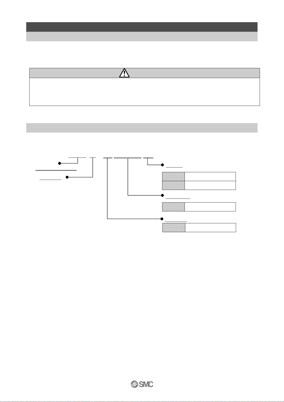
2. 2 How to Order
How to order is shown below.
LEC-GPR1□
Electric equipment
Controller
DIN rail
Nil Not mountable.
D Mountable
Applicable
PR1 Profibus DP V1
Unit types
G Gateway unit
- 7 -
Page 9
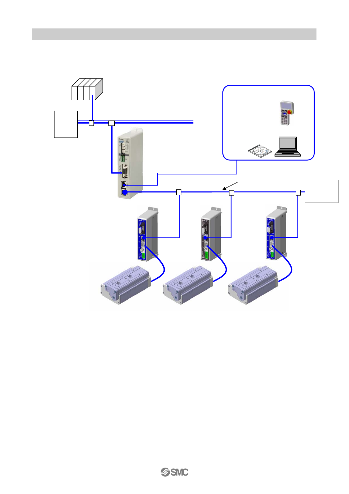
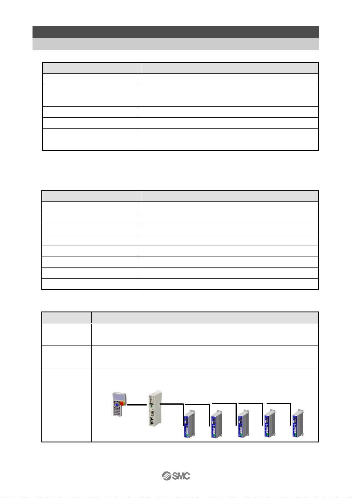
2. 3 Structure of the product
The system aplies this unit consists of the unit below.
System structure drawing.
PLC
Profibus
Ter m
Teaching box
LEC-T1-3G
inati
Motor controller
LEC Series
Electric actuator
LE Series
Gateway unit
LEC-GPR1
Controller setting software
LEC-W2
LEC serial communication (RS485)
Modbus communication
Termination
Resistor
・
- 8 -
Page 10
2. 4 Procedure (How to start the actuator)
Install, wire, set and operate the gateway unit referring to the procedure below when the product is
used for the first time.
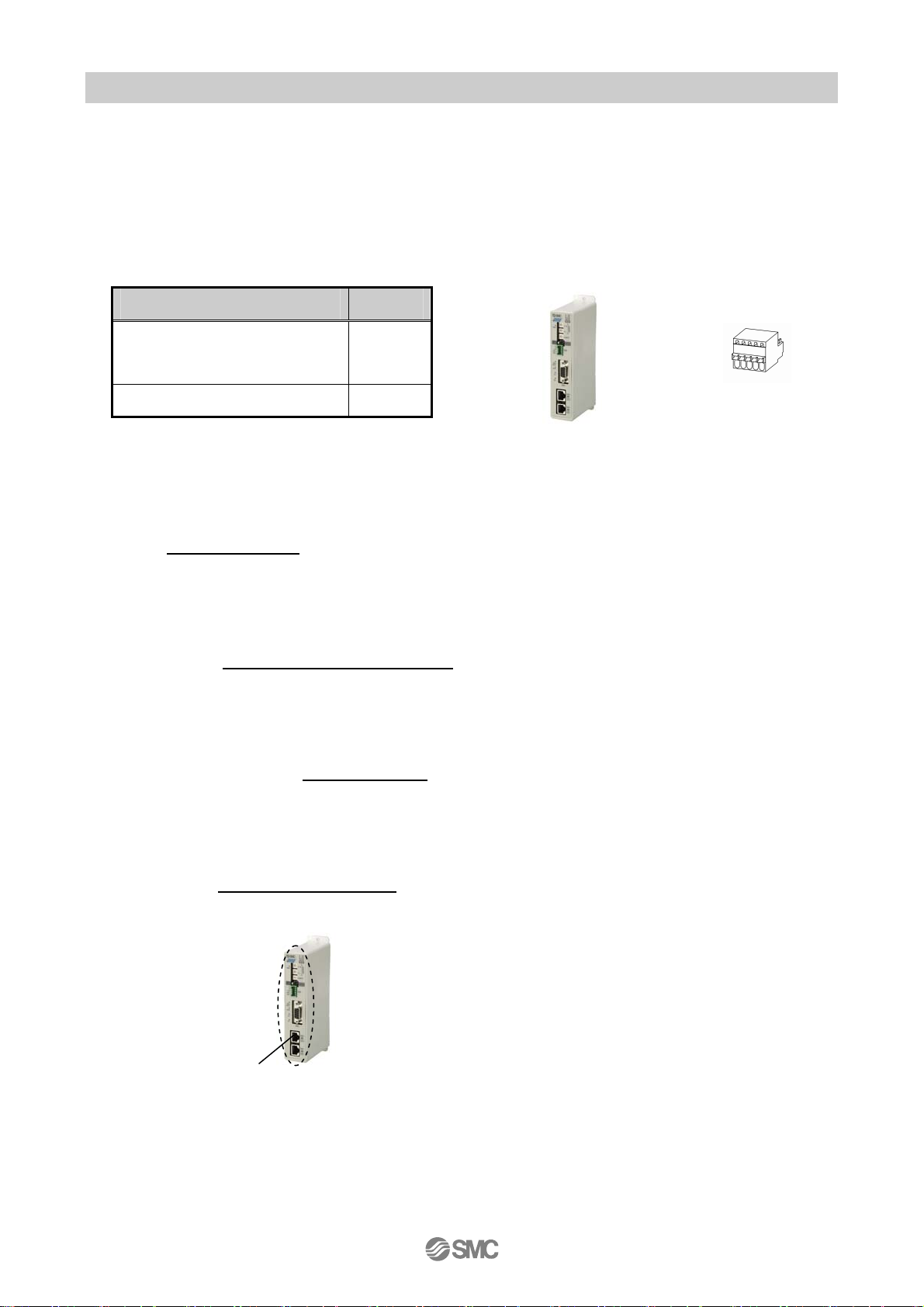
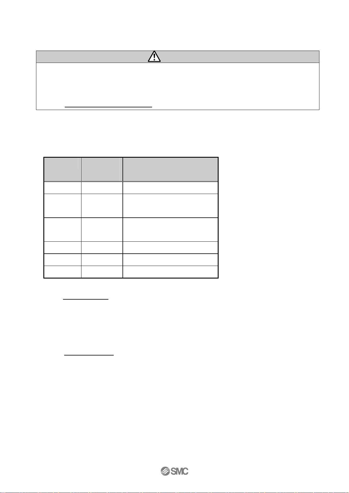
(1) Checking the content of the package
ter unpacking, check the description of the label to identify the gateway unit and the quantity of
Af
accessories.
Part’s name Quantity
Gateway unit
LEC-GPR1)
(
Power supply connector 1 pc.
1 pc.
Gateway unit
Power supply connector
(*)
These items are included if you ordered by the part number for a set of controller and actuator.
(2) Mounting the unit
Refer to 3.4
How to install
for the mounting of the gateway unit.
(3) Initial setting of the connect controller
The p
arameters of the controller’s, that are is connected to the gateway unit need to be set.
Refer to section 4.4 Setting of controller (LEC)
(4) Setting the unit
It
is necessary to set the node address and the communication speed by the rotary switch of the
gateway unit. Refer to section 4. Initial Setting
(5) Unit wiring / Connection
Conn
ect cables to the connectors(CN1 to CN3) of the gateway unit.
Refer to section 5. External connection
for the wiring of connectors.
Connector
- 9 -
Page 11
(6) Power supply
Supply po
wer 24V DC.
Caution
0V line of the gateway unit and the motor controller (LEC) have to be common.
When power is supplied in order of the gateway unit, then the controller (LEC), reset the data link
after supplying power to the controller (LEC).
(Refer to
If the condition is normal, LED on the front of the gateway unit turns on as the table below when power
is supplied.
12.4 Gateway unit control flag
Functions LED
condition
PWR Green On Supply of power
BUS STAT Green
Controller IF is communicating
for the details of data link reset).
Condition
flashing
ALM Green
flashing
CN2 STAT Off CN2 (TB/PC terminal) invalid
SF Green On
BF Green On
Refer to
If LED [ALM] on the front panel of the gateway unit shows red, an alarm conditions has occured.
(7) Operation
Refer to
series as well.
10. LED display
12. Memory
map
No alarm
System fault
BUS fault
for the explanation of LED lamps.
for the assignment of the memory. Read the operation manual of LEC
normal
normal
- 10 -
Page 12
3. Specifications
3. 1 Specifications
Basic specifications of the product.
Item Specifications
Rated voltage 24 VDC±10%
Current consumption 200mA or less (When teaching box is not connected)
300mA or less (When teaching box is connected)
Applicable controller Electric actuator controller (LEC series)
Product to be connected Max. 5pcs.
I/O occupation area
(Input/Output)
When conformity to UL is required, the electric actuator and controller should be used with a UL1310
Class 2 power supply.
【Profibus spec】
Item Specifications
Fieldbus Profibus DP –V1
Device type DP slave
Communication speed Auto baud rate
Address setting range 0 to 125
ID Number 1414
Configuration file GSD
Terminating resistor None
Connecter type D-sub
Input 57words / Output 57 words
【Controller IF communication spec. 】
Item Specifications
Serial
communication
Communication
speed
Cable length The cable for the teaching box (3m) and the electric actuator controller (5m x 5)
RS485 (Modbus protocol compliant)
115.2k or 230.4kbps (Select 115.2kbps when the teaching box is connected)
makes 28m of cable length. This is the maximum cable length.
3m
5m
- 11 -
5m
5m
5m 5m
Page 13

【Conditions of environment 】
Item Specifications
Applicable ambient temperature 0~40℃(No freezing)
Applicable ambient humidity 90%RH or less (No condensation)
Atmosphere No corrosive gas, flammable gas, oil mist, or particles.
Storage temperature -10~60℃(No freezing)
Storage humidity 90%RH or less (No condensation)
Vibration 4.9m/s2 (0.5G) or less
Enclosure IP20
Mass
200g (screw mount type)
220g (DIN rail mount type)
- 12 -
Page 14
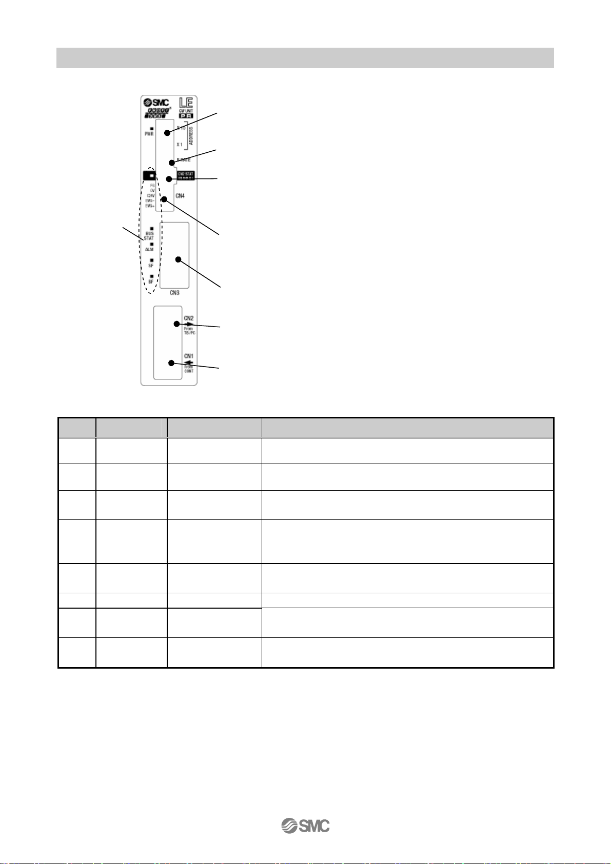
3. 2 Details of parts
Details of parts of the gateway unit
(1)
(2)
(3)
(4)
(5)
(6)
(7)
(8)
No. Display Description Detail
1 - LED lamp LED to indicate the condition of the gateway unit
2 ADDRESS Address switch This switch sets X1 and X10 in the address.
3 B RATE
4 CN2 SW
5 CN4
6 CN3 Bus connector Connect Profibus line.
7 CN2 TB/PC connector
8 CN1 CONT connector
Communication
speed
Communication
switch
Power supply
connector
The switch to set the communication speed of the
controller IF communication line.
Disables the communication with the controller IF
communication line, and ables the communication with the
equipment which are connected to CN2.
Connect the power supply and EMG.
The connector which connect LEC teaching box (LEC-T1)
or the ACT software Controller for setting (LEC-W2)
The connector for the controller IF communication line.
Connect the motor controller (LEC series).
- 13 -
Page 15
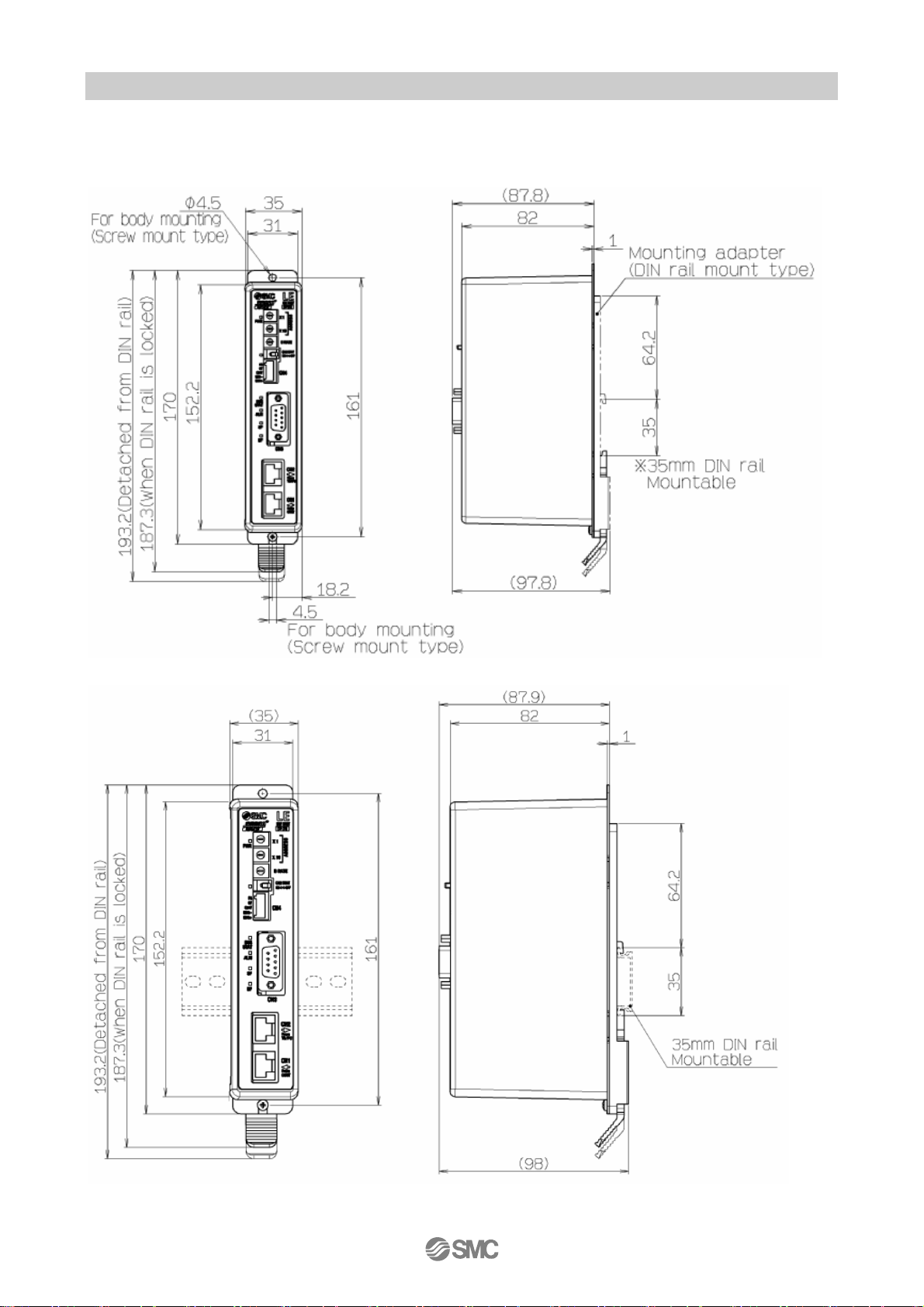
3.3 Outside dimension diagram
The outside view of this product is as shown in the diagram below:
(1) Screw mount type (LEC-GPR1)
(2) DIN rail mount type (LEC-GPR1
D)
- 14 -
Page 16
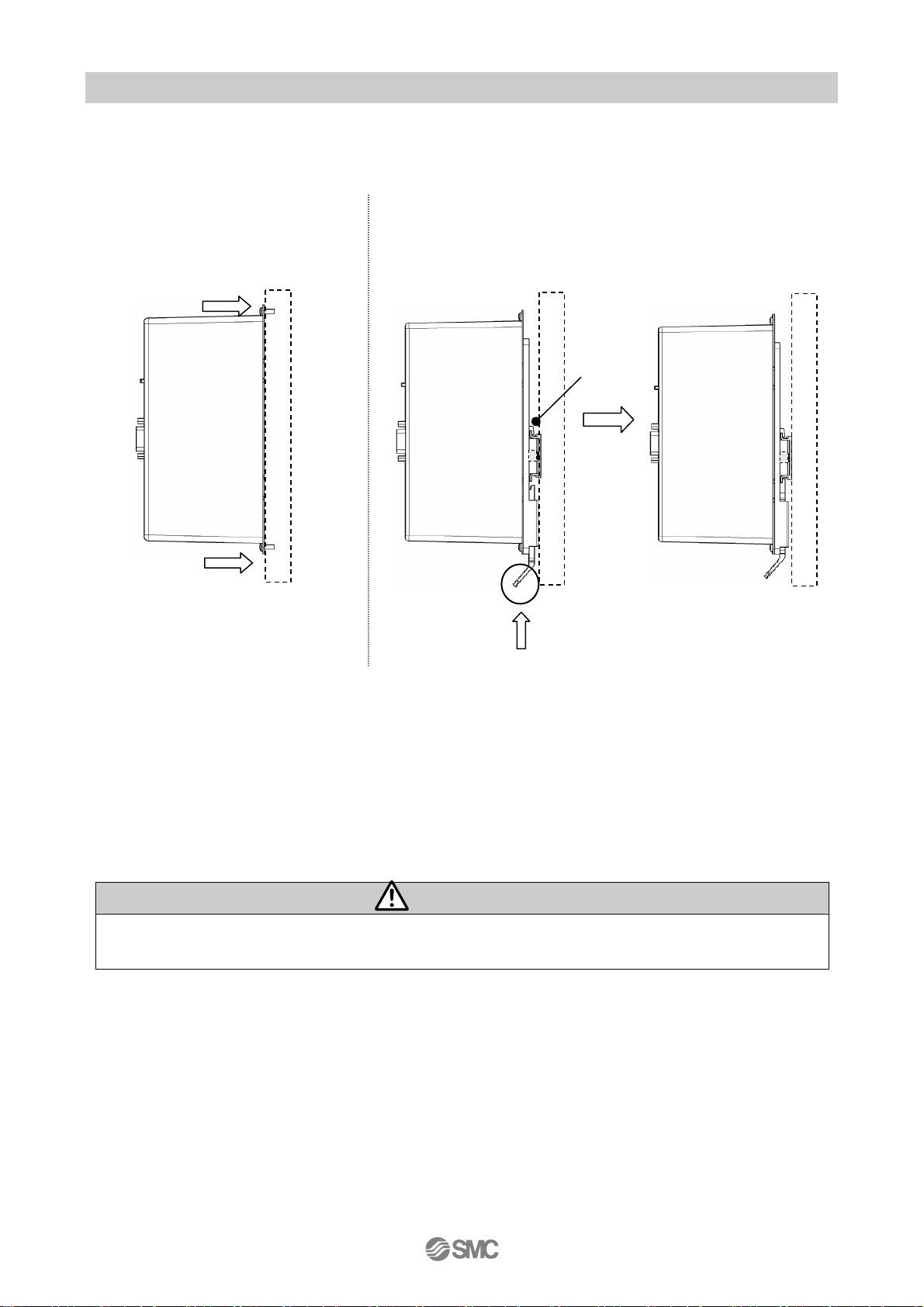
3.4 How to install
(1) How to install
There are two types of controllers; screw mount type and DIN rail mount type.
The followings are the descriptions on how to install each type:
[1] Screw mount type (LEC-GPR1)
(Installation with two M4 screws)
Screw direction
[2] DIN rail mount type (LEC-GPR1D)
(Installation with the DIN rail)
DIN rail is locked.
Screw direction
(2) Installation location
Please inst
not exceed 40
all this gateway unit at an appropriate place where the surrounding temperature will
o
C.
DIN rail
A
Hook the controller on the DIN rail and
press the lever of section A in the arrow
direction to lock it.
Caution
Install the gateway unit on a flat surface. Excessive pressure applied to the housing will damage the
gateway unit.
- 15 -
Page 17
)
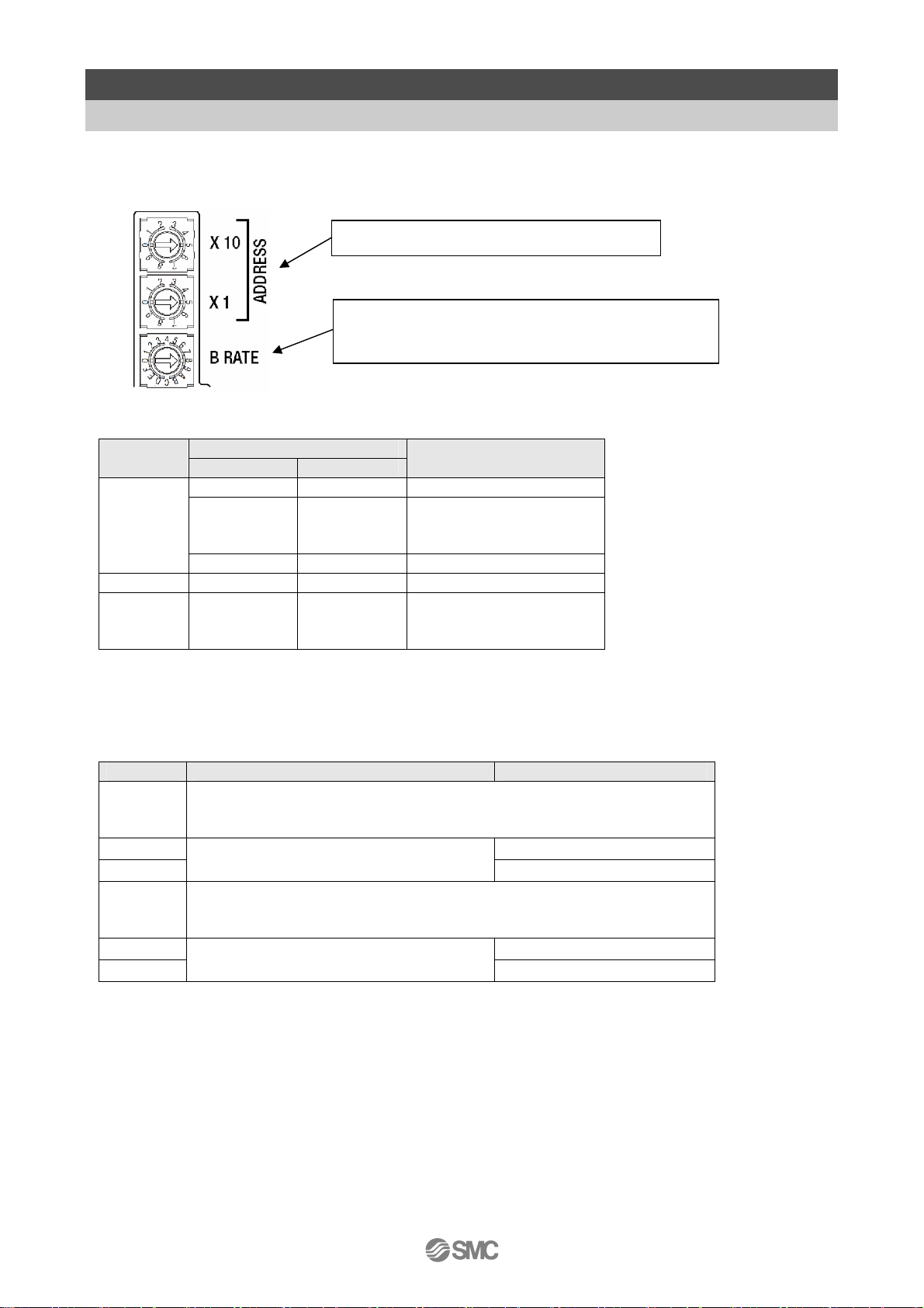
4. Initial Setting
4. 1. Switch (Address, B RATE)
The address of the gateway unit, and the transmission rate of motor controller LEC are set. Table below
shows the setting of switches.
Node address setting
ADDRESS B RATE
X10 X1
0 or 8
1 or 9 0 0 100
0
※ Do not set B RATE to the value of "Unused"
0 0 0
0
:
9
9 9 99
:
2
The address is shown. (0~99
The treble is shown about the transmission rate of
controller IF
Node address
1
:
8
1
:
5
1
:
98
101
:
125
※ Node address becomes 125 when a setup of a node address is set as a larger value than 125.
B RATE switch
B RATE the transmission rate of controller IF Nod address (X100)
F
:
Do not use
A
9 100 ~ 125
8
230.4kbps
1 ~ 99
7
:
Do not use
2
1 100 ~ 125
0
Caution1: Set the controller IF communication speed at 115.2kbps to use the teaching box (LEC-T1-).
Caution 2: Turn off the power supply in order to change the switch setting.
115.2kbps
1 ~ 99
- 16 -
Page 18

4. 2. Setting the switch to change the communication (CN2SW)
Turn ON the communication switch (CN2SW) during Profibus control. If the communication switch
(CN2SW) is turned off during Profibus control, communication error (data link error) is generated in the
gateway unit. Turn OFF communication switch (CN2SW) when changing the setting of controller
(LEC) by connecting the teaching box (LEC-T1-) of setting software (LEC-W2) to PC/TB connector
(CN2).
In this case, the communication from Profibus to the controller (LEC) is cut.
- 17 -
Page 19

4. 3. Setting of controller (LEC)
Initial parameter setting is necessary for the controller (LEC) which is connected to the gateway unit.
Set the following by directly connecting the teaching box (LEC-T1-) or the setting software to the
controller (LEC) before connecting the gateway unit.
Check the operation manual of the controller (LEC) and the teaching box (LEC-T1-) when setting the
controller (LEC).
4. 3. 1 ID setting
ID setting is necessary when connecting two or more controllers (LEC) to the gateway unit.
Assign ID to each controller (LEC) in serial number so that the numbers do not overlap. The setting
range of ID is between 1 to 5.
[Example of ID change procedure using the ACT Controller Setting software (LEC-W2)]
Start the setting software in Normal mode.
Open the parameter window.
4. 3. 2 Setting of the communication speed
It is necessary to match the gateway unit controller IF communication speed with the controller (LEC)
communication speed. Set the controller IF communication speed at 115,2kbps to use the teaching
box (LEC-T1-)
[Communication speed change procedure Setting software (LEC-W2)]
(1) Set the controller ID.
(Letters are changed to blue)
(2) Select Download.
(Changed ID is sent to the controller. ID
set value turns to black)
Start the setting software with Normal mode.
(1) Select [HELP] - [Password] from the menu. Password input screen below appears. Enter "password".
- 18 -
Page 20

(3)
(5)
)
(2) Set the controller so that the communication speed can be changed.
Change "Parameter protect" setting so that "Communication speed" parameter can be changed.
View the parameters of the controller.
Select "Basic" Tab - Item "Parameter protect" to "3: Common + Extend + Step"
The changed data is sent by clicking the download button, and the parameter protect set value text
changes from blue to black.
(3) Select the "Motor" Tab of the parameter window to change item "Comm speed" to "115200" for when
using Teaching box or "230400" for when using ACT Controller software.
(2)-1 Change parameter protect
to [3: Common + Extend + Step].
(2)-2 Select Download.
-1 Select the tag "Motor".
The changed data is sent by clicking the download button, and "Communication speed" set value is
changed from blue to black.
(3)-2 Change the communication speed
to 「115200」
(3)-3 Select Download.
or 「230400」(6
- 19 -
Page 21

(4) Change item "Parameter protect" using “Basic” tab of the display of (2) to "1: Common + Step data"
and click download.
(5) Close the ACT Controller software (LEC-W2) and turn OFF the controller (LEC) power supply. The
changed communication speed will be valid from the next time the controller (LEC) is turned on.
Caution
The communication speed of the gateway unit and the controller (LEC) must match.
If the communication speed does not match, the gateway unit and the controller (LEC) cannot
communicate.
Set the controller IF communication speed to 115,2kbps when using the teaching box (LEC-T1-)
The defaults setting of communication speed in the setting software (LEC-W2) is 38.6kbps.
After changing the communication speed, set the ACT Controller software (LEC-W2)
communication speed to 115.2kbps for Teaching box or 230.4kbps for the ACT controller software.
Do not change any parameters other than "ID setting"/"Communication speed setting".
Otherwise, malfunction can result.
Change "ID setting" / "Communication speed setting" to use the controller (LEC) stand-alone.
- 20 -
Page 22

4. 4 SIEMENS PLC S7 Connection Method
Below is an explanation of the LEC-GPR1 connection method with a SIEMENS PLX STEP7TM.
4.4.1 GSD File Installation
After STEP7TM has been stated.
Open[Hardware Configuration] screen.
Select “Opton-Install New GSD” From the mwnu var.
Select GSD File, and click the Open button.
After completiong the above steps,” Anybus-CC PROFIBUS DP-V1”will automatically be added to the
Hardware Catalog under the STE7TM[PROFIBUS DP][Additional Field Device][General]Folder.
* Screen data used on this document is taken for STEP7TM software by Siemens AG.
4.4.2 Adding Stations
Drag and drop “Anybus-CC PROFIBUS DP-V1”from the Hardware Catalogue to the station window.
[Properties-PROFIBUS interface”dialogue box will be displayed.
Enter the unit address on the dialogue boz.Please make sure that the address entered is the same as
the address set, using the switches.
Pree the OK button to confirm the address setting. “Anybus-CC PROFIBUS DP-V1”will be shown on
the station window.
- 21 -
Page 23

4.4.3 Adding Units
Select “Anybus-CC PROFIBUS DP-V1” from the station window.
Drag and drop the connected unit from [Hardware Catalogue] Windws.
・Input16word
・Input16word
・Input16word
・Universal module
I/O Type: Input,Length: 9,Unit: Words,Consistent over: Total length
・Output16word
・Output16word
・Output16word
・Universal module
I/O Type: Output,Length: 9,Unit:Words,Consistent over: Total length
Please give "I Address" and "Q Address" to me with the crack so as not to overlap.
The figure below is an example to set by "I Address 0-113" and "Q Address 0-113".
It is set completion by downloading the configuration data to PLC.
Input Total 57words
Output Total 57words
- 22 -
Page 24

5. External connection
5. 1 CN4: Power supply connector
Connect the power supply. The gateway unit and the controller (LEC) should have the common 0V line.
Gateway
Unit
CN4
Power supply line
Power supply
(24 VDC)
(Cables, PLC and power supply are prepared by customer)
* Refer to 6. CN4: Power supply connector
5. 2 CN3: Bus connector
Connect the Profibus line and the controller (LEC) with the communication cable (LEC-CG□-□)
Gateway
Unit
CN3
* Refer to 7. CN3: Bus connector
Profibus line.
(Cables, PLC and power supply are prepared by customer)
PLC
5. 3 CN1: CONT connector
Connect the gateway unit and the controller (LEC) to communication cable (LEC-CG□-□).
Gateway
unit
Controller input power supply
24 VDC
CN1
Terminating Resistor
(120 1/4W)
CN4
* Refer to section 8. CN1: Controller IF communication connector (CONT)
Controller (LEC) Controller (LEC)
CN4
Controller (LEC)
- 23 -
CN4
Page 25

Caution
Do not pull out the cable between the gateway unit and the cable, or cut off the power
supply to the controller (LEC). Communication is interrupted.
5. 4 CN2: PC/TB connector
The connector which connects the tools teaching box (LEC-T1-3*G*) or PC (LEC-W2) for setting the
controller (LEC.
The data link of the gateway unit and the controller (LEC) data is cut by turning off CN2SW or
stopping data link, and communication with the tool teaching box (LEC-T1-3*G*) for setting the controller
or PC (LEC-W2) becomes possible.
(1) Connecting the teaching box
Gateway unit
CN2
Teaching box
(with 3m of cable)
(2) Connecting PC
(Communication cable, USB cable, conversion unit)
Gateway unit
CN2CN2
Conversion unit
USB cable
(A-miniB type)
Communication cable
※Refer to 9.CN2:TB/PC Power supply connector for usage.
Caution
Do not start the setting software during data link.
Controller setting software
モニタ
モニタ
現在位置
現在位置
現在速度
現在速度
設定
設定
1
テスト
1
テスト
2
テスト
2
テスト
3
テスト
3
テスト
mm
mm
120.3
120.3
mm/s
mm/s
200
200
位置 速度
位置 速度
100
100
200
200
50
50
動作中
動作中
アラーム
アラーム
500
500
1000
1000
200
200
PC
(PC is prepared by customer)
Otherwise, communication error (data link error) is generated with the gateway unit.
- 24 -
Page 26

6. CN4: Power supply connector
6.1 Power supply connector
Specifications of the communication connector in accessory
terminal Function Functional explanation
1 EMG + EMG signal output +
Output terminal of the emergency stop
2 EMG - EMG signal output -
switch of the teaching box.
3 C 24V Power supply + terminal
Power supply terminal of the Gateway unit
5 4 3 2 1
4 0V
Power supply - Terminal
5 FG FG Terminal Grounding terminal
(Power to the teaching box is supplied from
this terminal)
Caution
(1) 0V line of the gateway unit and the motor controller (LEC) have to be common.
(2) When conformity to UL is required, the electric actuator and controller should be used with a
UL1310 Class 2 power supply.
6.2 Power line
(Power lines are prepared by customer. Specifications below need to be satisfied)
Item Specifications
Applicable
wire
Size
Peeled wire
length
Do not connect multiple wires to one terminal.
Power terminal
(24V,0V)
EMG signal output
(EMG+,EMG-)
AWG20: Single line,No insulation sleeve, Twisted wire with
bar terminal.
*The rated temperature for the insulation coating: 60
degrees C or more.
AWG20: Single line,No insulation sleeve, Twisted wire with
bar terminal.
*Rated temperature of the insulation cover is 60 degrees C
or higher
8mm
Caution
- 25 -
Page 27

Caution
(1) The earthling should be the dedicated grounding point. It should be a functional ground with less
than 100 resistance.
(2) The ground point should be near this gateway unit to make the wire length shorter.
6.3 Wiring of the shutdown circuit
The gateway unit has the terminal (EMG+, EMG-) which outputs the stop switch signal of the teaching
Gateway unit
Recommended Functional grounding
Other device
Gateway unit
Not Recommended grounding
Other device
box when the communication switch (CN2SW) is turned on. Set the terminal to EMG terminal of the
controller (LEC) to use the teaching box.
Teaching
box
CN2
Internal
circuit
RY
Switch to change
the communication
(CN2SW)
Shutdown
circuit
CN4
EMG +
EMG-
24V
0V
Gateway unit
- 26 -
Page 28

Caution
T urn on the communication s witch (CN2SW) before install / removal of the teaching box to
/ from the gateway unit.
If EMG+ and EMG- terminals are connected to the controller (LEC) or a shutdown circuit and the
communication switch is turned off when the teaching box is not connected, connected controller
(LEC) or the shutdown circuit receives stop signal (Open between EMG+ and EMG-) and operation
stops
- 27 -
Page 29

【Shut
down circuit Example】
Shutdown circuit with gateway Check the circuit referring the controller (LEC) operation manual.
【Example of the circuit】ex. LEC6
DC24
Shutdown is lifted
Switch
Ry
0V
Stop
Gateway
Unit
EMG +
EMG -
Power supply plug (1st. unit)
BK RLS
EMG
C 24V
M 24V
0V
Switch
Ry
Ry
Surge suppressor
24V
0V
Controller
input power
Power supply plug (2nd. unit)
BK RLS
EMG
C 24V
M 24V
0V
Ry
24V
0V
Controller
input power
Power supply plug (3rd. unit)
BK RLS
EMG
C 24V
M 24V
0V
Ry
24V
0V
Controller
input power
Caution
When the stop signal is input, the controller (LEC) is stopped with max deceleration speed, and servo
motor is turned off.
- 28 -
Page 30

7. CN3: Bus conecter
BUS: D-sub 9-pin socket
No Designation Description
1 - Unused
9
8
7
6
Use the PROFIBUS DP connector with bus cable.
(e.g. 6GK1 500-0FC10,6ES7 972-0BA12-0XA0,manufactured by Siemens)
A shielded twisted pair valbe for PROFIBUS DP should be used.
5
4
3
2
1
2 - Unused
3 RXD・TXD-P Receive/transmit data,positive
4 - Unused
5 DGND Data ground(reference potential
to VP)
6 VP Power supply puluse (P5V)
7 - Unused
8 RXD/TXD-N Receive/transmit data,negative
9 - Unused
- 29 -
Page 31

8. CN1: Controller IF communication connector (CONT)
8. 1 Connection
One unit can control up to 5 pcs. of controllers (LEC).
The example of link connection which consists of telecommunication cable LEC-CG 1-1 and cable
LEC-CG 2-1 between branches is shown below.
5
1 LEC-CG1-
a) RJ45 male connector with a shield(8P)
b) M12 4pin
male connector
2 LEC-CGD
c) M12 4pin
female connector
b) M12 4pin
male connector
3 LEC-CG2-
b) M12 4pin
male connector
2 LEC-CGD
b) M12 4pin
male connector
4
1 LEC-CG1-
No Description Part number Content
1 Communication cable cable LEC-CG1-
2 Branch connector LEC-CGD The junction cable to connect the gateway and the controller.
3 Cable between branches LEC-CG2-
4 Terminating Resistor
a) RJ45 male connector with a shield(8P)
K 0.3m
L 0.5m
1 1m
K 0.3m
L 0.5m
1 1m
1 LEC-CG1-
a) RJ45 male connector with a shield(8P)
Cable to connect the gateway unit CN1 and the branch
connector, or controller (LEC) CN4 and the branch connector.
Cable to connect the branch connector.
Termination on RS-485 Bus (120 Ohms)
Recommended connector
:XS2C-D4** [OMRON Corporation]
5 RJ-45 connector dust cover
-
LEC-CAP-X22
- 30 -
Dust adhere when the RJ-45 connector is not connected with the
CN1 or CN2 connector.
Please attach a cover when you prevent the adhesion such as
dust.
120Ω 1/4W
Page 32

Recommended connector
No Description Part number
a) RJ45 male connector with a shield(8P) TM21P-88P [HIROSE ELECTRIC CO., LTD.]
b) M12 4pinmale connector HR24-8DJ4PE550A(73) [HIROSE ELECTRIC CO., LTD.]
XS2G-D4** [OMRON Corporation]
c) M12 4pin female connector HR24-8DP4S300(73) [HIROSE ELECTRIC CO., LTD.]
XS2C-D4** [OMRON Corporation]
- 31 -
Page 33

8. 2 Wiring diagram
For you reference, the example of wiring of the gateway unit CN1 is shown below.
The communication line from the gateway unit CN1 branches to each controller (LEC) by the branch
connector. It is recommended to connect the terminating resistor (120 1/4W) to the branch connector
at the terminal.
When connecting the cable, the shield of the cable becomes same potential as 0V of the controller
power supply.
When using it, do not contact it to conductive parts of switchboard, other instruments, wiring, etc.
Gateway unit CN1
Description Pin No.
N.C. 1
N.C. 2
SD+ 3
SD- 4
N.C. 5
N.C. 6
N.C. 7
N.C. 8
Shield
Branch
1 1
2 2
3 3
4 4
1234
Branch
1 1
2 2
3 3
4 4
1 2 3 4
Controller CN4
Description Pin No.
EMG+ 1
EMG- 2
SD+ 3
SD- 4
EN_SW+ 5
ON 6
DC24V 7
GND 8
Shield
Controller CN4
Description Pin No.
EMG+ 1
EMG- 2
SD+ 3
SD- 4
EN_SW+ 5
ON 6
DC24V 7
GND 8
Shield
- 32 -
Page 34

9. CN2: TB/PC connector
9. 1 How to use
This connector is for setting the controller (LEC) which is connected to the gateway unit by the teaching
box or the set software.
When the communication switch (CN2SW) is turned off, the communication from Profibus DP to the
controller is disconnected, and the signal line of CN2 and CN1 is connected. From now on, the setting of
each controller is possible.
The following is the setting procedure of the controller (LEC) when the teaching box or PC setting
software us connected to the gateway unit.
【Procedure to start setting】
(1) Connect the teaching box or PC to CN2 of gateway unit.
(2) Turn off the communication switch (CN2SW).
(3) Reset signal is sent to all controllers (LEC) which are connected to the gateway unit, and the
communication from Profibus to the controller (LEC) is disconnected. Reset signal stops all actuators.
(4) Communication from the teaching box or PC becomes available.
【Procedure to finish setting】
(1) Finish the PC setting software.
(2) Turn on the communication switch (CN2SW).
(In case of the teaching box, power supply is turned off at this point)
(3) Communication starts after the reset signal is sent from the gateway unit to the controller (LEC).
Reset signal stops all the actuators immediately after communication starts.
(4) Remove the teaching box or PC from the CN2 of gateway unit.
Caution
Do not start the setting software during data link (CN2SW turn on).
Otherwise, communication error (data link error) is generated with the gateway unit.
Use the teaching box and the setting software after finishing startup process of the gateway
unit (After ALM lamp green blinks). (CN2SW turn off etc.)
The gateway unit communicates with controller (LEC) as startup processing immediately
after turning on of the power supply.
At this time, if the teaching box or the setting software communicate to controller (LEC),
communication error is generated.
- 33 -
Page 35

10. LED display
10. 1 LED display
LED name Content
Off Power is not supplied PWR Power supply
status is displayed
SN2SW
Controller IF
STAT
ALM
BF Bus fault
status
The alarm status.
(Profibus)
(Profibus)
Green On Power is supplied
Off When switch ON CN2STAT ON, OFF status of
Green ON When switch OFF
Green flashing Communicating BUS
Off Communication
disconnected
Green flashing Normal status
Orange flashing Warning generated
Red On When alarm is
generated or
communication data link
is disconnected.
Green ON Normal status SF System fault
Off Error status
Green ON Normal status
Green flashing Stop status
Off Error status
- 34 -
Page 36

10. 2 Controller IF communication status and LED display
Gateway unit status PWR BUS STAT ALM CN2 STAT
Supply of power Green On Off Off Off
Controller (LEC) and normal
communication
Command to interrupt data link is being
given
CN2SW ON Command to interrupt data
link is being given
Contr
oller
IF
Communication error with
some controllers (LEC) is
detected.
Communication error is
detected for all controllers
(LEC), or IF communication
speed of the controller is
incorrect.
Green On Green
flashing
Green On Off Green
Green On Off Green
Green On Green
flashing
Green On Green
flashing
Green
flashing
flashing
flashing
Orange
flashes
Red On Off
Off
Off
Green On
Off
- 35 -
Page 37

11. Mode
11. 1 Outline
This unit has 3 types of operation mode. These modes can be switched by mode change. Current mode
can be checked by mode return
Refer to “12.4(1) Return of the mode” for “Return of the Mode”.
Step data input mode
Operating actuator by using the memory of the gateway unit which corresponds to parallel IO of
controller (LEC).
Numerical data input mode
Operating actuator by using the memory of the gateway unit which corresponds to parallel IO of
controller (LEC), and operating actuator by directly sending the parameters which like a position, a
speed etc., are available.
Step data writing mode
Operating actuator by using the memory of the gateway unit which corresponds to parallel IO of
controller (LEC), and editing step data of the LEC controllers through the gateway unit, are available.
Please confirm the setting method of "Mode chenge" and "Mode return" by "Gateway control flag" and
"Gateway unit state flag".
11. 2. Step data input mode
This is the mode that Operating actuator by using the memory of the gateway unit which corresponds
to parallel IO of controller (LEC).
In case that “ID” setting of the controller(LEC) is “1”, the memory which corresponds to the parallel IO
of controller can be operated by I Address 14,15 and Q Address 14,15.
Refer to the manual of controller (LEC) for detail of the function and the operation of parallel IO.
11. 3. Numerical data input mode
This is the mode that operating actuator by sending to controller (LEC) the data which is a position, a
speed etc.
The actuator moves with the position, the speed etc which is specified by sent data.
In this mode, the command by using parallel I/O is available.
Before operating the actuator by directly sending the data which like a position, a speed etc, SVON and
return to origin should be finished.
Please make same operation as performing SVON and return to origin with parallel IO by using the
corresponding memory.
And operating the actuator is availavle by using the memory which corresponds to parallel IO of
LEC6 controller.
Refer to the manual of controller (LEC) for detail of the function and the operation of parallel IO.
The data such as the current position can be read by “Setting numerical data”.
Refer to “12.4(5) Setting numerical data” for “Setting numerical data”.
- 36 -
Page 38

●Operation commanded by numerical data input mode (ID=1)
(1) Write “0” in Q_Address 16 .
(2) Write the motion profile (position, speed…) in Q_Address 17 to 33.
Refer to "7.1 Step data" of the operation manual of the controller(LEC).
(3) Write “1” in Q_Address 16. Then, the command of the driving is sent to the controller (LEC).
(4) When the sending to the controller(LEC) is completed, “Sending completed” (I_Address 33.1)
changes from “0” to “1” and the actuator starts driving.
(5) And, when the actuator completes driving, “INP” (I_Address 15.3) is changed from “0” to “1”.
Refer to "6.3 Parallel IO input" of the operation manual of the controller(LEC) for detail of INP
signal.
(6) Write “0” in Q_Address16.
Then, “Sending completed” (I_Address 33.1) is changed from “1” to “0”.
Operation command
Data (Position, speed)
Sending
Sending completed
Operation
INP
1
2
3
6
4
5
- 37 -
Page 39

11. 4. Data writing mode
This is the mode that the step data of the controller(LEC) can be changed through the gateway unit.
After changing it, the changed step data is reflected by commanding to drive the changed step data.
And the same functions as step data input mode are available in this mode.
The driving and the return to origin etc. are commanded by using the memory which corresponds to
parallel IO of LEC controller.
Refer to the manual of controller (LEC) for detail of the function and the operation of parallel IO.
●Writing step data method
(1)Write “0” in Q_Address 17.
(2)Write the motion profile (position, speed…) in Q_Address 18 to 33.
Refer to "7.1 Step data" of the operation manual of the controller(LEC).
(3)Write the step data number which is changed in Q_Address 16. (Setting data range is from 0 to 63.)
(4)Write “1” in Q_Address 17. Then, the data which is written in avobe (2) are sent to the
controller(LEC).
(5)When the sending to the controller(LEC) is completed, “Sending completed” (I_Address .33.1)
is changed from “0” to “1”.
(6)Write “0” in Q_Address 17 .
Then, “Sending completed ” (I_Address .33.1) changes from “1” to “0”.
- 38 -
Page 40

12. Memory map
12. 1 Memory assignment
Gateway unit --> Higher level device [IN]
I_Address Data name
0
1
2
3
4
5
…
13
Correspond-
I_Address
Ing ID
Gateway unit control flag
Unused (Do not use it.) -
Bit/Byte
No.
Data name
Model/
Size
Value
range
Corresponding
mode
All modes
Corresponding
Unit
mode
0 OUT0 bit 0,1 -
1 OUT1 bit 0,1 -
2 OUT2 bit 0,1 -
14
ID1
15
3 OUT3 bit 0,1 -
4 OUT4 bit 0,1 -
5 OUT5 bit 0,1 -
6 - bit 0 -
7 - bit 0 -
All modes
0 BUSY bit 0,1 -
1 SVRE bit 0,1 -
2 SETON bit 0,1 -
3 INP bit 0,1 -
4 AREA bit 0,1 -
5 WAREA bit 0,1 -
6 ESTOP bit 0,1 -
7 ALARM bit 0,1 -
・Please refer the operation manual of the step motor controller (LECP6) and the servo motor controller
(LECA6) to check the detail of each signal.
- 39 -
Page 41

Correspond-
ing ID
I_
Address
Bit/Byte
No.
16 3
Data
name
Model/
Size
Value range Unit
Correspond-
Ing mode
ID1
17 2
18 1
19 0
20 H
21 L
22 H
23 L
24 3
25 2
26 1
27 0
28 - Alarm 0 to 255 -
29 - Alarm 0 to 255 -
30 - Alarm 0 to 255 -
Current
4 +/-2147483647 0.01mm
position
Current
2 0 to 65500 mm/s
speed
Current
2 0 to 300 %
Force
Target
4 +/-2147483647 0.01mm
position
4
Numerical data
input
Numerical data
input
ID2
ID3
ID4
ID5
31 - Alarm
32
Controller IF status flag (ID=1)
33
34 to 53
54 to 73
74 to 93
94 to 113
0 to 255 -
All modes
Same as ID1
Same as ID1
Same as ID1
Same as ID1
- 40 -
Page 42

Higher level device --> Gateway unit [OUT]
Q_Address Data name
0
1
Gateway unit status flag
2
3
4
Corresponding
mode
All modes
Correspond-
ing ID
ID1
5
…
13
Q_
Address
14
Bit/Byte
No.
0 IN0 bit 0,1 -
1 IN1 bit 0,1 -
2 IN2 bit 0,1 -
3 IN3 bit 0,1 -
4 IN4 bit 0,1 -
5 IN5 bit 0,1 -
6 - bit 0 -
7 - bit 0 -
0 HOLD bit 0,1 -
1 SVON bit 0,1 -
Unused (Do not use it.) -
Data name
Model/
Value range Unit
Size
Corresponding
All mode
mode
2 DRIVE bit 0,1 -
15
3 RESET bit 0,1 -
4 SETUP bit 0,1 -
5 - bit 0 -
6 - bit 0 -
7 - bit 0 -
- 41 -
Page 43

Correspond
-ing D
Q_
Address
Bit/Byte
No.
Data name
Model/
Size
Value range Unit
Correspond
-ing mode
ID1
16 -
Start flag
Step data No
Operation
17 -
Note)
18 H
Speed 2 0 to 65500 mm/s
19 L
20 3
21 2
Position 4 +/-2147483647 0.01mm
22 1
23 0
24 H
Acceleration 2 0 to 65500 mm/s
25 L
26 H
Deceleration 2 0 to 65500 mm/s
27 L
28 - Pushing force 1 0 to 30 10%
0: no send
1: send
1
0 to 63
1: Absolute
1
2: Relative
-
-
Numerical
data input
Data writting
2
2
Numerical
data input
Data writting
29 - Threshold 1 0 to 30 10%
30 - Pushing speed 1 0 to 255 mm/s
Positioning
1 0 to 30 10%
thrust
In pos 2 0 to 65500 0.01mm
Same as ID1
Same as ID1
Same as ID1
Same as ID1
ID2
ID3
ID4
ID5
31 -
32 H
33 L
34 to 53
54 to 73
74 to 93
94 to
113
Note) "0" is "no send" at mode of data writing. "1" and "2" contain "send" at mode of data writing.
- 42 -
Page 44

12. 2 Controller IF status flag(IN Data)
Controller IF flag is sent back to each ID ID=1 is shown below as an example
[ID=1]
I_Address
32
bit
7 6 5 4 3 2 1 0
- - - - -
-
Abnormal
station
Connect station
33
- - - - -
-
Sending
Sending
completed
(1) Connect station
1 (ON) appears when it is confirmed that the motor controller (LEC) is connected. 0 (OFF) appears
when the connection is not confirmed.
(2) Abnormal station
0 (OFF) appears when the communication with the motor controller is normal at the connect station. 1
(ON) appears when the communication is not normal.
(3) Sending
1 (ON) appears while the operation command from the motor controller (LEC) is given and the
sending of the operation data for the motor controller is completed at numerical data input mode. 0
(OFF) appears when the sending is completed.
(4) Sending completed
1 (ON) appears when the sending of the operation command data to the motor controller (LEC) is
completed at the numerical data input mode. 1 (ON) appears while the sending of the operation
command data to the motor controller when the operation command is (ID=1).
Start flag
Sending
Sending completed
Sending command
12. 3 Gateway unit status flag(IN Data)
The flag to indicate the gateway communication status.
I_Address
bit
0
1
2
3 Return of the final station number
(1) Return of the mode
Current mode is displayed
Address0
Bit1 Bit0
0 0 Step data input mode
0 1 Numerical data input mode
1 0 Data writing mode
7 6 5 4 3 2 1 0
Commu
Initial ALARM READY
nicating
Return of the read numerical data
Mode name
- 43 -
- -
Return of the mode
Page 45

(2) READY
1 (ON) appears when the gateway is activated.
(3) ALARM
1 (ON) appears when one or more abnormal station are present, and the alarm is generated. 0 (OFF)
appears when alarm is not generated.
(4) Initial
0 (OFF) appears during processing the initial for check the connect station. 1 (ON) appears when the
processing of the initial is completed.
(5) During communication
1(ON) appears when communication is made for one or more station. 0 (OFF) appears when not
communicated.
In one of following cases, communication is not made.
CN2SW is ON.
Stop[InputAddress0.7] is ON.
All the connect stations become abnormal and the communication is stopped.
(6) Return of the read numerical data (Valid only in numerical data input mode)
ON (1) appears in ID bit if numerical data can be read. OFF (0) appears when the data can not be read.
The command to read numerical data is given by “Setting numerical data”.
I_Address
bit
7 6 5 4 3 2 1 0
1 - - - ID5 ID4 ID3 ID2 ID1
2 - - - - - - - -
(7) Return of the final station number
Return the range of the ID of the controller (LEC) to communication when the initial is processed. ID
number is returned in binary digit.
ID
bit
3 2 1 0
1 0 0 0 1
2 0 0 1 0
3 0 0 1 1
: :
5 0 1 0 1
- 44 -
Page 46

12. 4 Gateway unit control flag(OUT Data)
The flag to control the gateway communication status.
bit
Q_Address
0 Stop - Restart Reset - - Mode command
7 6 5 4 3 2 1 0
1
Setting numerical data
2
3 - - - - Setting the final station number
(1) Mode command
Command the mode. Mode return is updated when the set mode becomes valid.
Address0
Mode name
Bit1 Bit0
0 0 Step data input mode
0 1 Numerical data input mode
1 0 Data writing mode
(2) Reset
Communication to the abnormal station restart when 0 (FF) is changed to 1 (ON). But, it is invalid when
Stop is 1(ON) or CN2SW is ON.
(3) Restart
Initial processing is executed again when 0 (OFF) is changed to 1 (ON). But, it is invalid when Stop is 1
(ON) or CN2SW is ON.
(4) Stop
All communications to the connected motor controller (LEC) are stopped when 0 (OFF) is changed to 1
(ON). Communication restart by chancing to 0 (OFF) from 1 (ON).
(5) Setting numerical data (Valid only in direct setting mode)
ON (1) appears in ID bit if numerical data can be read. OFF (0) appears when the data can not be read.
Q_Address
bit
7 6 5 4 3 2 1 0
1 - - - ID5 ID4 ID3 ID2 ID1
2 - - - - - - - -
(6) Return of the final station number
Indicates the range of the ID of the controller (LEC) to communication when the initial is processed. ID
number is set in binary digit.
Input range is from 1 to 5. If the set value is lower than 0 or larger than 5, 5 is set.
ID
bit
3 2 1 0
1 0 0 0 1
2 0 0 1 0
3 0 0 1 1
: :
5 0 1 0 1
- 45 -
Page 47

13. Precautions for controlling the controller (LEC)
13. 1. Communication delay between the gateway unit unit and the controller(LEC)
There is communication delay between the gateway unit and the controller (LEC). Please refer to the
procedure below for the control procedure taking the delay into consideration
For details of each signal, please refer to the operation manual of each motor controller (LEC) to be
connected.
Example of operation indication with step data input mode
Command
(Input signal)
(1) DRIVE input ON (1) ⇒ Confirm that all OUT0 to 5 in the
(2) DRIVE input OFF (0) ⇒ Confirmed that OUT0 to 5 in the
(3) INP is ON (1) and BUSY is OFF
Cautions for the above example
When the operation is ordered right after the operation shown below, the response of DRIVE above
are not recognized because OUT0 to 5 in the data information are all OFF (0) before turning ON (1) the
Response (Output signal)
data information are changed to
OFF (0) from values before
DRIVE input ON (1).
data information is the value
within IN0 to 5 in specified data.
(0)
- Confirm the
completion of
the operation.
DRIVE input. In this case, take measures against the communication delay by using the timer.
【Condition in which OUT0 to 5 in the data information is all OFF】
- Supply of power
- During and the right after the returning to origin position.
- RESET input ON
- After DRIVE input OFF(0) after commanding to start step data No.0
- 46 -
Page 48

13. 2. Guideline of the Response delay between the Gateway and the Motor Control Unit
The gateway unit communicates with the motor controller (LEC) to read the controller status and
commands the controller. The time for the communication causes delay in the response.
Please take this into consideration when selecting the PLC program.
PLC
Profi Bus
Gateway
Unit
Communication to read the motor controller status
The gateway unit communicates one by one in order. The communication time is approximately 30ms
per unit. When reading of numerical data is validated during Numerical data input mode or data rewrite
mode, it takes another 30ms for communicating with valid controller (LEC).
Communication for commanding the motor controller
When rewrite of the remote I/O and the register is commanded by Profibus master, it takes 30ms for
communicating with the target controller (LEC).
Response delay depends on the number of the connected motor controllers (LEC) and rewrite
frequency.
Ex. 1) Response time guideline when four controllers are connected in step data input mode.
4 pcs. × approx. 30ms = Approx. 120ms +
[:Communication time to rewrite the remote I/O and the register]
Ex. 2) Response time guideline when twelve controllers are connected in step data input mode.
5 pcs. × approx. 30ms = Approx. 150ms +
[:Communication time to rewrite the remote I/O and the register]
Ex. 3) Response time guideline when 5 controllers are connected in numerical data input mode (3
controllers are valid for reading numerical data).
5 pcs. × approx. 30ms + 3pcs. x approx. 30ms = Approx. 240ms +
[:Communication time to rewrite the remote I/O and the register]
※This response time does not include the response time of Profibus and motor controller (LEC), and
processing time of PLC.
Communication between the
gateway unit and the controller
Motor controller
(LEC)
Motor controller
(LEC)
Motor controller
(LEC)
- 47 -
Page 49

14. Wiring of cables/Common precautions
Warning
1. Adjusting, mounting or wiring change should never be done before shutting off the power
supply to the product.
Electrical shock, malfunction and damaged can result.
2. Never disassemble the cable. Use only specified cables.
3. Never connect or disconnect the cable or connector with power on.
Caution
1. Wire the connector securely. Do not apply any voltage to the terminals other than those
specified in the product Manual.
2. Wire the connector securely.
Check for correct connector wiring and polarity.
3. Take appropriate measures against noise.
Noise in a signal line may cause malfunction. As a countermeasure, separate high voltage and low
voltage cables, and shorten wiring lengths, etc.
4. Do not route wires and cables together with power or high voltage cables.
The product can malfunction due to interference of noise and surge voltage from power and high
voltage cables to the signal line. Route the wires of the product separately from power or high
voltage cables.
5. Take care that actuator movement does not catch cables.
6. Operate with cables secured. Avoid bending cables at sharp angles where they enter the product.
7. Avoid twisting, folding, rotating or applying an external force to the cable.
Risk of electric shock, wire break, contact failure and lost of control for the product can happen.
8. Fix the motor cable protruding from the product in place before using.
The motor and lock cables are not robotic type cables and can be damaged when moved.Therefore
do not place it in a flexible moving tube.
9. The cable connecting the actuator and controller (LEC) is superior in bending resistance, but
should not be placed into a flexible moving tube with a radius smaller than the specified
value.
( Min. 50 mm)
10. Confirm proper wiring of the product.
Poor insulation (interference with other circuits, poor insulation between terminals and etc.) can
apply excessive voltage or current to the product causing damage.
11. The Speed / pushing force may vary, depending on the cable length, load and mounting
conditions etc..
If the cable length exceeds 5m, the speed / pushing force will be reduced by a maximum of 10% per
5m. (If cable length is 15m: Maximum 20% reduction.)
[Transportation]
Caution
1. Do not carry or sw ing the product by the motor or the cable
- 48 -
Page 50

15. Electric actuators/Common precautions
15.1 Design and selection
Warning
1. Be sure to read the Operation Manual.
Handling or usage/operation other than that specified in the Operation Manual may lead to
breakage and operation failure of the product.
Any damage attributed to the use beyond the specifications is not guaranteed.
2. There is a possibility of dangerous sudden action by the product if sliding parts of machinery
are twisted due to external forces, etc.
In such cases, human injury may occur, such as by catching hands or feet in the machinery, or damage to the
machinery itself may occur. Design the machinery should be designed to avoid such dangers.
3. A protective cover is recommended to minimize the risk of personal injury.
If a driven object and moving parts of the product are in close proximity, personal injury may occur.
Design the system to avoid contact with the human body.
4. Securely tighten all stationary parts and connected parts so that they will not become loose.
When the product operates with high frequency or is installed where there is a lot of vibration,
ensure that all parts remain secure.
5. Consider a possible loss of power source.
Take measures to prevent injury and equipment damage even in the case of a power source failure.
6. Consider behavior of emergency stop of whole system.
Design the system so that human injury and/or damage to machinery and equipment will not be
caused, when it is stopped by a safety device for abnormal conditions such as a power outage or a
manual emergency stop of whole system.
7. Consider the action when operation is restarted after an emergency stop or abnormal stop of
whole system.
Design the system so that human injury or equipment damage will not occur upon restart of
operation of whole system.
8. Disassembly and modification prohibited
Do not modify or reconstruct (including additional machining) the product. An injury or failure can result.
9. Do not use stop signal,"EMG" of the controller and stop switch on the teaching box as the
emergency stop of system.
The stop signal, "EMG" of controller and the stop switch on the teaching box are for decelerating
and stopping the actuator.
Design the system with an emergency stop circuit which is applied relevant safety standard separately.
10. When using it for vertical application, it is necessary to build in a safety device.
The rod may fall due to the weight of work. The safety device should not interfere with normal
operation of the machine.
Caution
1. Operate within the limits of the maximum usable stroke.
The product will be damaged if it is used with the stroke which is over the maximum stroke. Refer to
the specifications of the product.
2. When the product repeatedly cycles with partial strokes, operate it at a full stroke at least
once a day or every 1000 strokes.
Otherwise, lubrication can run out.
- 49 -
Page 51

3. Do not use the product in applications where excessive external force or impact force is
applied to it.
The product can be damaged. Each component that includes motor is made with accurate tolerance.
So even slightly deformed or miss-alignment of component may lead operation failure of the
product.
4. Refer to a common auto switch /matter (Best Pneumatics No 2) w hen an auto switch is built
in and used.
5. Return to origin cannot return while operating.
It cannot be done during positioning operation, pushing operation and pushing.
6. When conformity to UL is required, the electric actuator and controller should be used
with a UL1310 Class 2 power supply.
15.2 Mounting
Warning
1. Install and operate the product only after reading the Operation Manual carefully and
understanding its contents. Keep the manual in a safe place future reference.
2. Observe the tightening torque for screws.
Tighten the screws to the recommended torque for mounting the product.
3. Do not make any alterations to this product.
Alterations made to this product may lead to a loss of durability and damage to the product, which
can lead to human injury and damage to other equipment and machinery.
4. When using external guide, the guide axis should be parallel to the actuator axis.
There will be damage/excessive wear on the lead screw if the external guide is not parallel.
5. When an external guide is used, connect the moving parts of the product and the load in
such a way that there is no interference at any point within the stroke.
Do not scratch or dent the sliding parts of the product tube or piston rod etc., by striking or grasping
them with other objects. Components are manufactured to precise tolerances, so that even a slight
deformation may cause faulty operation.
6. Prevent the seizure of rotating parts.
Prevent the seizure of rotating parts (pins, etc.) by applying grease.
7. Do not use the product until you verify that the equipment can be operated properly.
After mounting or repair, connect the power supply to the product and perform appropriate functional
inspections to check it is mounted properly.
8. At the overhang mounted impeller fixation
There is a possibility that the power at the bending moment damages the actuator when moving it at
high speed.
The support metal fittings that suppress the vibration of the main body of the actuator are installed.
Lower and use speed for the state that the actuator doesn't vibrate.
9. When attaching work piece, do not apply strong impact or large moment.
If an external force over the allowable moment is applied, it may cause looseness in the guide unit,
an increase in sliding resistance or other problems.
10. Maintenance space.
Allow sufficient space for maintenance and inspection.
- 50 -
Page 52

15.3 Handling
Warning
1. Do not touch the motor while in operation.
The surface temperature of the motor can increase to approx. 90oC to 100oC due to operating
conditions. Energizing alone may also cause this temperature increase. As it may cause burns, do
not touch the motor when in operation.
2. If abnormal heating, smoking or fire, etc., occurs in the product, immediately shut off the
power supply.
3. Immediately stop operation if abnormal operation noise or vibration occurs.
If abnormal operation noise or vibration occurs, the product may have been mounted incorrectly.
Unless operation of the product is stopped for inspection, the product can be seriously damaged.
4. Never touch the rotating part of the motor or moving part of the actuator while in operation.
5. When installing, adjusting, inspecting or performing maintenance on the product, controller and
related equipment, be sure to shut off the power supply to each of them. Then, lock it so that no one
other than the person working can turn the power on, or implem ent measures such as a safety plug.
6.
In the case of the actuator that has a servo motor (24VDC), the “motor phase detection step"
is done by inputting the servo on signal just after the controller power is turned on. The
“motor phase detection step” operates the table/rod to the maximum distance of the lead
screw. (The motor rot ates in the reverse direction if the t able hits an obstacle such as the end
stop damper.) Take the “motor phase detection step” into consideration for the installation
and operation of this actuator.
Caution
1.
Keep the controller and product combined as delivered for use.
The product is set in parameters for shipment. If it is combined with a different parameter, failure can result.
2.
Check the product for the following points before operation.
a) Damage to electric driving line and signal lines
b) Looseness of the connector to each power line and signal line
c) Looseness of the actuator/cylinder and controller/driver mounting
d) Abnormal operation
e) Emergency stop of the total system
3. When more than one person is performing work, decide on the procedures, signals,
measures and resolution for abnormal conditions before beginning the work. Also,
designate a person to supervise work other than those performing work.
4. Actual speed of the product will be changed by the workload.
Before selecting a product, check the catalog for the instructions regarding selection and
specifications.
5. Do not apply a load, impact or resistance in addition to a transferred load during return to origin.
In the case of the return to origin by pushing force, additional force will cause displacement of the
origin position since it is based on detected motor torque.
6. Do not remove the name plate.
7. Operation test should be done by low speed. Start operation by predefined speed after
confirming there is no trouble.
[Earth]
Warning
1. Please give the earth of the actuator.
2. Please make it to the earth of the exclusive use. The earth construction is D seed.
(Below earth resistance 100)
3. Please shorten the distance until the actuator and earth.
- 51 -
Page 53

[Unpackaging]
Caution
1. Check the received product is as ordered.
If a different product is installed from the one ordered, injury or damage can result.
15.4 Operating environment
Warning
1. Avoid use in the following environments.
a. Locations where a large amount of dusts and cutting chips are airborne.
b. Locations where the ambient temperature is outside the range of the temperature specification
(refer to specifications).
c. Locations where the ambient humidity is outside the range of the humidity specification (refer to
specifications).
d. Locations where corrosive gas, flammable gas, sea water, water and steam are present.
e. Locations where strong magnetic or electric fields are generated.
f. Locations where direct vibration or impact is applied to the product.
g. Areas that are dusty, or are exposed to splashes of water and oil drops.
h. Areas exposed to direct sunlight (ultraviolet ray).
2. Do not use in an environment where the product is directly exposed to liquid, such as cutting oils.
If cutting oils, coolant or oil mist contaminates the product, failure or increased sliding resistance can
result.
3. Install a protective cover when the product is used in an environment directly exposed to
foreign matters such as dust, cutting chips and spatter.
Play or increased sliding resistance can result.
4. Shade the sunlight in the place where the product is applied with direct sunshine.
5. Shield the valve from radiated heat generated by nearby heat sources.
When there is a heat source surrounding the product, the radiated heat from the heat source can
increase the temperature of the product beyond the operating temperature range. Protect it with a
cover, etc.
6. Grease oil can be decreased due to external environment and operating conditions, and it
deteriorates lubrication performance to shorten the life of the product.
[Storage]
Warning
1. Do not store the product in a place in direct contact with rain or water drops or is exposed to
harmful gas or liquid.
2. Store in an area that is shaded from direct sunlight and has a temperature and humidity
within the specified range (-10oC to 60oC and 35 to 85% No condensation or freezing.
3. Do not apply vibration and impact to the product during storage.
- 52 -
Page 54

15.5 Maintenance
Warning
1. Do not disassemble or repair the product.
Fire or electric shock can result.
2. Before modifying or checking the wiring, the voltage should be checked with a tester 5
minutes after the power supply is turned off.
Electrical shock can result.
Caution
1. Maintenance should be performed according to the procedure indicated in the Operating
Manual.
Incorrect handling can cause injury, damage or malfunction of equipment and machinery.
2. Removal of product.
When equipment is serviced, first confirm that measures are in place to prevent dropping of work
pieces and run-away of equipment, etc, and then cut the power supply to the system. When
machinery is restarted, check that operation is normal with actuators in the proper positions.
[Lubrication]
Caution
1. The product has been lubricated for life at manufacturer, and does not require lubrication in
service.
Contact SMC if lubrication will be applied.
15.6 Precautions for actuator with lock
Warning
1. Do not use the lock as a safety lock or a control that requires a locking force.
The lock used for the product with a lock is designed to prevent dropping of work piece.
2. For vertical mounting, use the product with a lock.
If the product is not equipped with a lock, the product will move and drop the work piece when
the power is removed.
3. "Measures against drops” means preventing a work piece from dropping due to its
weight when the product operation is stopped and the power supply is turned off.
4. Do not apply an impact load or strong vibration while the lock is activated.
If an external impact load or strong vibration is applied to the product, the lock will lose it’s
holding force and damage to the sliding part of the lock or reduced lifetime can result. The
same situations will happen when the lock slips due to a force over the thurst of the product, as
this accelerates the wear to the lock.
5. Do not apply liquid or oil and grease to the lock or its surrounding.
When liquid or oil and grease is applied to the sliding part of the lock, its holding force will
reduce significantly.
6. Take measures against drops and check that safety is assured before mounting,
adjustment and inspection of the product.
If the lock is released with the product mounted vertically, a work piece can drop due to its weight.
- 53 -
Page 55

16.
Gateway unit and its peripheral devices /Specific product precautions
16.1 Design and selection
Warning
1. Be sure to apply the specified voltage.
Otherwise, a malfunction and breakage of the gateway unit may be caused.
If the applied voltage is lower than the specified, it is possible that the load cannot be moved due to
an internal voltage drop. Please check the operating voltage before use.
2. Do not operate beyond the specifications.
It may cause a fire, malfunction or actuator damage can result. Please check the specifications before
use.
3. Install an emergency stop circuit.
Please install an emergency stop outside of the enclosure so that it can stop the system operation
immediately and intercept the power supply.
4. In order to prevent danger and damage due to the breakdown and the malfunction of this
product, which may occur at a certain probability, a backup system should be established
previously by giving a multiple-layered structure or a fail-safe design to the equipment, etc.
5. If a fire or danger against the personnel is expected due to an abnormal heat generation,
ignition, smoking of the product, etc., cut off the power supply for this product and the
system immediately.
6. Use UL1310 compliant Class 2 power supply unit for direct current.
16.2 Handling
Warning
1. The inside of the gatew ay unit and its connector should not be touched.
It may cause an electric shock or damage to the controller.
2. Do not perform the operation or setting of this equipment with wet hands.
It may cause an electric shock.
3. Product with damage or the one lacking of any components should not be used.
It may cause an electric shock, fire, or injury.
4. Use only the specified combination between the controller and electric actuator.
It may cause damage to the controller or the actuator.
5. Be careful not to be caught or hit by the workpiece while the actuator is moving.
It may cause an injury.
6. Do not connect the power supply or power on the product before confirming the area where
the work moves is safe.
The movement of the work may cause accident.
7. Do not touch the product when it is energized and for some time after power has been
disconnected, as it is very hot.
It may lead to a burn due to the high temperature.
8. Check the voltage using a tester for more than 5 minute after power-off in case of installation,
wiring and maintenance.
There is a possibility of getting electric shock, fire and injury.
- 54 -
Page 56

9. Do not use in an area where dust, powder dust, water or oil is in the air.
It will cause failure or malfunction.
10. Do not use in an area where a magnetic field is generated.
It will cause failure or malfunction.
11. Do not install in the environment of flammable gas, corrosive gas and explosive gas.
It could lead to fire, explosion and corrosion.
12. Radiant heat from strong heat supplys such as a furnace, direct sunlight, etc. should not be
applied to the product.
It will cause failure of the gateway unit or its peripheral devices.
13. Do not use the product in an environment subject to a temperature cycle.
It will cause failure of the gateway unit or its peripheral devices.
14. Do not use in a place where surges are generated.
When there are units that generate a large amount of surge around the product (e.g., solenoid type
lifters, high frequency induction furnaces, motors, etc.), this may cause deterioration or damage to
the product’s' internal circuit. Avoid supplys of surge generation and crossed lines.
15. The product is not immune to lightening strikes. Take measures against lightening strikes in
the system.
16. Do not install this product in an environment under the effect of vibrations and impacts.
It will cause failure or malfunction.
17. If this product is used with a relay or solenoid valve, they should be the surge absorbing
element built-in type.
16.3 Mounting
Warning
1. The gateway unit and its peripheral devices should be installed on a fire-proof material.
A direct installation on or near a flammable material may cause fire.
2. Do not install this product in a place subject to vibrations and impacts.
It may cause an electric shock, fire, or injury.
3. Take measure so that the operating temperature of this gateway unit and its peripheral
devices are within the range of the specifications. Also, this controller should be installed
with 50mm or larger spaces between each side of it and the other structures or components.
It may cause a malfunction of the controller and its peripheral devices and a fire.
4. Do not mount this gateway unit and its peripheral devices together with a large-sized
electromagnetic contactor or no-fuse breaker, which generates vibration, on the same panel.
Mount them on different panels, or keep the controller and its peripheral devices away from
such a vibration supply.
5. This gateway unit and its peripheral devices should be installed on a flat surface.
If the mounting surface is distorted or not flat, an unacceptable force may be added to the housing,
etc. to cause troubles.
- 55 -
Page 57

16.4 Electrical wiring
Warning
1. Do not apply any excessive force to cables by repeated bending, tensioning or placing a
heavy object on the cables.
It may cause an electric shock, fire, or breaking of wire.
2. Connect w ires and cables corre ctly.
Incorrect wiring could break he gateway unit or its peripheral devices depending on the seriousness.
3. Do not connect wires while the power is supplied.
It can break the gateway unit or its peripheral devices could be damaged to cause a malfunction.
4. Do not carry this product by holding its cables.
It may cause an injury or damage to the product.
5. Do not connect power cable or high-voltage cable in the same wiring route as the unit.
Te wires to the gateway unit or its peripheral devices can be interrupted with noise or induced surge
voltage from power lines or high-voltage lines and malfunction could be caused.
Separate the wiring of the gateway unit and its peripheral device from that of power line and high
voltage line.
6. Verify the insulation of wiring.
Insulation failure (interference with other circuit, poor insulation between terminals and etc.) could
introduce excessive voltage or current to the gateway unit or its peripheral devices and damage
them.
16.5 Power supply
Caution
1. Use a power supply that has low noise between lines and between power and ground.
In cases where noise is high, an isolation transformer should be used.
2. To prevent surges from lightning, an appropriate measure should be taken. Ground the surge
absorber for lightning separately from the grounding of the gateway unit and its peripheral
devices.
16.6 Grounding
Warning
1. Be sure to carry out grounding in order to ensure the noise tolerance of the gateway unit.
It may cause an electric shock or fire.
2. Dedicated grounding should be used.
Grounding should be to a D-class ground (Ground resistance of 100 or less.)
3. Grounding should be performed near the unit as much as possible to shorten the grounding
distance.
4. In the unlikely event that malfunction is caused by the ground, it may be disconnected.
- 56 -
Page 58

16.7 Maintenace
Warning
1. Perform a maintenance check periodically
Confirm wiring and screws are not loose.
Loose screws or wires may cause unintentional malfunction.
2. Conduct an appropriate functional inspection after completing the maintenance.
In case of any abnormities (in the case that the actuator does no move, etc.), stop the operation of
the system. Otherwise, an unexpected malfunction may occur and it will become impossible to
secure the safety.
3. Do not disassemble, modify or repair this gateway unit and the peripheral equipment.
4. Do not put anything conductive or flammable inside of this gateway unit.
It may cause a fire and explosion.
5. Do not conduct an insulation resistance test and withstand voltage test on this product.
6. Ensure sufficient space for maintenance activities. Provide space required for
maintenance.
Design the system that allows required space for maintenance.
7. Do not used solvents such as benzene, thinner etc. to clean the gateway unit.
They could damage the surface of the body and erase the markings on the body.
Use a soft cloth to remove stains.
For heavy stains, use a cloth soaked with diluted neutral detergent and fully squeezed, then wipe up
the stains again with a dry cloth.
- 57 -
Page 59

Revision history
No.LEC-OM03401
Feb/2012 1st printing
No.LEC-OM03402
Mar/2012 Revision
No.LEC-OM03403
Apr/2012 Revision
Addition to notes about UL recognition
4-14-1, Sotokanda, Chiyoda-ku, Tokyo 101-0021 JAPAN
Tel: + 81 3 5207 8249 Fax: +81 3 5298 5362
URL http://www.smcworld.com
Note: Specifications are subject to change without prior notice and any obligation on the part of the manufacturer.
© 2012 SMC Corporation All Rights Reserved
- 58 -
 Loading...