

SMC Networks LC8-B*H*-M*-Q Series, LC8-B*H*-V*-Q Series Installation And Maintenance Manual
Page 1
3 UNPACKING
CAUTION
Confirm that the product you have received is what you ordered. Injury/damage may occur if an incorrect product
is installed.
3.1 Included Items - Master
3.2 Available Accessories - Master
3.3 Included items - Slave
3.4 Available Accessories - Slave
Notice for using the master unit
1) Use master unit for the single unit operation. (The slave unit cannot be used alone)
2) In case of triple axis operation or more, Contact SMC for the usage and the condition.
Notice for using the Slave unit
1) Origin back motion start moving for both of master and slave unit. Design your system without hitting any
machines in the origin back motion.
2) When input start signal, the operation data for all axis are activated. Please input "incremental coordinate(I),
position 0 mm" in the operation data for the axis you don't want to activate.
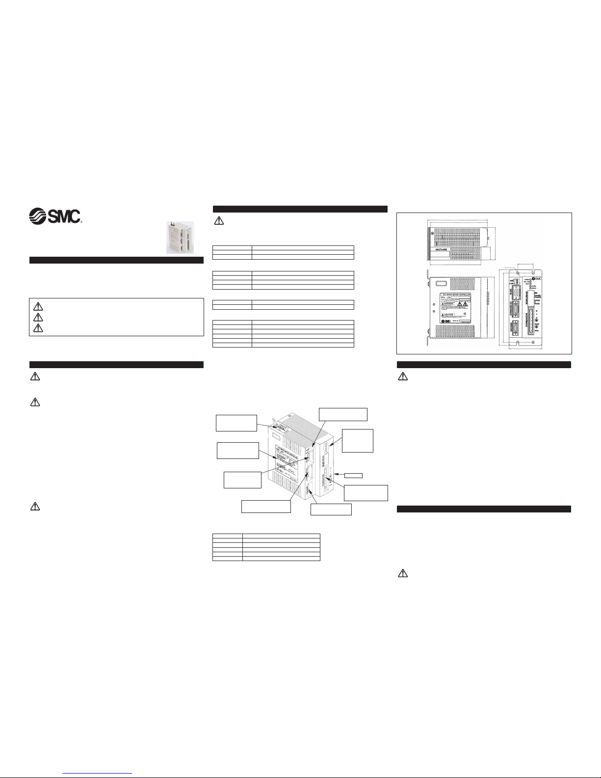
3.5 Parts Identification
3.6 Applicable Actuator Types
This manual should be read in conjunction with the current catalogue
Applicable model numbers:
LC8-BH-M-Q Master
LC8-BH-V-Q Slave
1 SAFETY
For safe and proper operation, read this manual thoroughly before use so as to understand the Installation,
maintenance and safety checks etc. Make sure that you have a good knowledge of the equipment and all the
relevant safety precautions prior to installation.
Keep this Installation and Maintenance Manual handy so that operators can refer to it.
1.1 General recommendation
These safety instructions are intended to prevent a hazardous situation and/or equipment damage.
These instructions indicate the level of potential hazard by a label of "CAUTION", "WARNING" or "DANGER".
To ensure safety, please observe ISO 10218 Note 1) and JIS B 8433 Note2) and other safety practices.
Note 1) ISO 10218: Manipulating industrial robots.
Note 2) JIS B 8433: General rules for robot safety.
2 GENERAL
DANGER (In general)
1) Avoid the use of these products in an explosive atmosphere, it could cause injury and fire.
2) Do not perform work on the positioning driver when the power is on. Ensure that the power is switched off
before starting work, to avoid risk of electric shock.
WARNING
1. The compatibility of positioning drivers and electric actuators is the responsibility of the person
who designs the system or decides its specifications.
Since the products specified here are used in various operating conditions, their compatibility for the specific
system must be based on specifications or after analysis and/or tests to meet your specific requirements.
2. Only trained personnel should operate this equipment.
Positioning drivers can be dangerous if an operator is unfamiliar with them. Assembly, handling or repair of
systems using positioning drivers should be performed by trained and experienced operators.
3. Do not service machinery/equipment or attempt to remove components until safe conditions are
confirmed.
1) Inspection and maintenance of machinery/equipment should only be performed after confirmation of safe
locked-out control positions.
2) When equipment is to be removed, confirm the safety process as mentioned above, and shut off and
isolate the power supply for this equipment.
3) Before machinery/equipment is restarted, confirm that all safety measures are in effect.
4. Contact SMC if the product is to be used in any of the following conditions:
1) Conditions and environments beyond the given specifications, or if the product is to be used outdoors.
2) Installation on equipment in conjunction with atomic energy, medical equipment, food and beverages, or
safety equipment.
3) An application, which has the possibility of having negative effects on people, property or animals,
requiring special safety analysis.
CAUTION
1) Read thoroughly and follow this manual before installation, operation and maintenance. There is the possibility
of electric shock, injury and fire.
2) Do not use product out of specifications.
3) Do not use damaged drivers and actuators. It may lead to injury and fire.
4) Do not remove any plate or label attached to the product.
5) Use drivers and actuators in the specified combinations. Fire and failure could occur otherwise.
6) Pay attention to the rise in temperature of the driver, motor and peripheral equipment. It may lead to burning.
(Transport)
1) Make sure not to drop the product during transport. There is a possibility of injury and damage.
2) Do not hold cables during transport. It may lead to failure and injury.
3) Follow the instructions to avoid collapse of cargo piles due to overloading.
(Disposal)
1) The disposal of actuators is as general industrial waste.
(Storage)
1) Do not keep the product in a place where it is exposed to rain, water droplets or harmful gases and liquids.
2) Store in a place within the specified temperature and humidity range (-10° to 60°C, 10 to 85% without
condensation) avoiding direct sunlight.
3.7 Dimensions
4 INSTALLATION
CAUTION
1) Take safety measures such as the installation of a protective cover if there is the possibility that operators will
be exposed to danger of injury by electric shock.
2) Avoid repeated bending and tension forces being applied to power transmission lines of motor cables. It may
lead to breaking of wires.
3) Securely tighten all fixing screws and connectors of positioning driver, so as to prevent them from becoming
loose.
4) Run power and signal cables separately to avoid risk noise of interference.
5) Avoid use in the following operating environments.
a) Locations with a lot of debris or dust, or where chips may enter the positioning driver.
b) Locations where the ambient temperature is outside the range specified. (Refer to specifications)
c) Locations where the ambient humidity is outside the specified range. (Refer to specifications)
d) Locations where corrosive or combustible gases are generated.
e) Locations where strong magnetic or electric fields are generated.
f) Locations where direct vibration or impact shock etc. will be applied to the positioning driver.
g) Locations with a lot of dust and where water or oil splash onto the positioning driver.
6) Perform the following inspections before operating an actuator or positioning driver.
a) Inspection for damage to the actuator/positioning driver power lines.
b) Inspection for looseness of the connectors to each power line and signal line.
c) Inspection for looseness of the actuator/positioning driver mountings.
d) Inspection for abnormal operation of the actuator/positioning driver.
e) Emergency stop buttons are not operated.
f) Implement preventive measures such as a fence enclosure to prevent human entry to the operating area
of the actuator/ positioning driver.
g) Take measures to perform an emergency stop by using a sensor, etc. To prevent human entry into the
above mentioned operating area.
7) Design Points
a) Do not allow impact or shock load to be applied to the positioning driver.
b) A protective cover is recommended to minimize the risk of human injury.
5 CE DIRECTIVES
5.1 Machinery Directive 98/37/EC
SMC Electrical Actuators are defined as components and thus are intended for incorporation into machinery and
assemblies, which are covered by the Machinery Directive 98/37/EC (refer to annex II B). CE marking is therefore
not applied to Electrical Actuators.
5.2 Electromagnetic Compatibility (EMC) Directive 89/336/EEC
SMC use CE marked motors and drivers which comply with all relavant EMC guidelines as set out in the EMC
directive 89/336/EEC. Please refer to the relevant manuals for EMC installation guidelines.
5.3 Low Voltage Directive (LVD) 73/23/EEC
The drivers and motors for these products are in compliance with the LVD. Please refer to the relevant manuals
for installation guidelines.
CAUTION
Always observe installation guidelines and safety instructions of motors and drivers to ensure electrical safety and
compliance with the Directives.
Installation and Maintenance Manual for
LC8 Series AC Servo Positioning Driver
CAUTION: Operator error could result in injury or equipment damage.
WARNING: Operator error could result in serious injury or loss of life.
DANGER: In extreme conditions, there is the possibility of serious injury or loss of life.
LC8 - TF109GB
LC8-1-MP Motor/Power connector
LC8-1-B Mounting bracket kit (Only with mounting bracket option)
LC8-1-W1 Controller install software for LC8
LC8-1-CN Command I/O connector
LC8-1-1050 Command I/O connector with cable (0.5m)
LC8-1-1050P Command I/O connector with cable with blades (0.5m)
LC8-1-R03C Communication cable for RS-232C (3m)
LC8-1-MP Motor/Power connector
LC8-1-B Mounting bracket kit (Only with mounting bracket option)
LC8-1-C2 Communication cable for 2 Axis
LC8-1-C3 Communication cable for 3 Axis
LC8-1-C4 Communication cable for 4 Axis
LC8-1-C5 Communication cable for 5 Axis
LC8-1-C6 Communication cable for 6 Axis
LC8-1-C7 Communication cable for 7 Axis
Multi-axis connector
-connects to other
Positioning drivers for
multi-axis configuration
DIP switches
-used to set multi-axis ID No.
and home direction
Status indicators
-Power
-Set-On
-Busy
-Alarm
-Error
Heatsink
Power/motor connector
-used for the main power
supply input and connects
to the motor power leads
Encoder connector
-connects to the encoder
in the AC motor
Command I/O connector
-used for I/O signals to control
a PLC, etc.
RS-232 connector
-used to communicate
with a personal
computer
Nameplate
-indicates the AC servo
Positioning driver model &
ratings
Series Actuator Model no.
LJ1H LJ1H8--(-X)-Q
LJ1S LJ1S8--(-X)-Q
LG1H LG1H2182--F-Q
LTF6 LTF68E---Q
LTF8 LTF88F---Q
(136.5)
130
75
30
115
35
141
175
160
75
4-ø5.5
Page 2
8 WIRING
8.1 General
CAUTION
1) Refer to the relevant drivers manuals for the wiring.
2) Determine the correct power supply voltage from the product label.
8.2 Wiring the LC8
DANGER
1) Do not excessively bend, pull or pinch the power cable or motor leads. Electric shock may result.
2) To avoid electric shock, disconnect the power and wait one minute before performing maintenance or inspection
on the wiring.
3) Carefully follow the wiring diagrams when making wiring connections to avoid fire or electric shock.
4) Do not reverse the motor drive leads. Also be careful not to ground the wires or short them.
5) Do not attempt to use the signal terminals for other than the specified signals.
CAUTION
1) Do not attempt to measure the insulation resistance. Damage may result.
2) Ground resistance must be lower than 0.1 Ω.
3) Install appropriate surge protection to avoid malfunction.
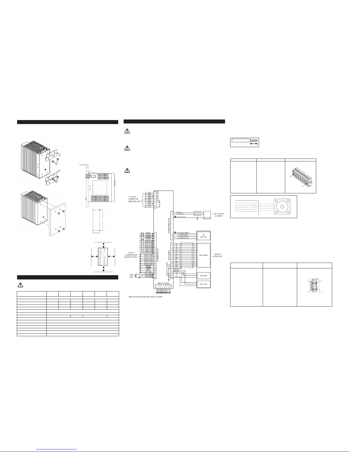
8.3 Wiring Diagram
6 MOUNTING
There are two mounting possibilities: Bracket and Bulkhead mounting
6.1 Mounting Dimensions
To avoid overheating keep the minimum distance from enclosure as shown
below.
Installing the controller in an enclosure may result in overheating due to
increased temperatures inside the enclosure. Ensure the enclosure is ventilated sufficiently to prevent the ambient temperature from exceeding 50ºC
(122ºF) for 50 Watt and 100 Watt controllers and 40°C (104°F) for 200 Watt
controllers. Additionally, allow at least 50mm (2”) above and below the controllers, 20mm (.78”) between controllers and 30mm (1.18”) between the
controllers and sides of the enclosure for ventilation.
7 LC8 POSITIONING DRIVER SPECIFICATIONS
WARNING
Never operate the actuator out of specifications.
8.4 LC8 positioning driver and motor power supply
Use specification table in section 7 to determine the correct fuse or circuit breaker for protecting the LC8
controllers:
Cable Termination
Strip the wire and twist the ends. (Do not solder the core.)
The Motor/Power connector is used to connect the LC8 to the AC power supply and to connect the motor power
cable to the LC8. The Motor/Power connector has a separate plug that is inserted into the header in the LC8 so
that the wiring can be quickly disconnected and reconnected for servicing.
8.5 RS 232 interface
The RS-232 connector is used for serial communication to a PC. An RS-232 communication cable is available from
SMC or from most distributors of computer supplies.
8.6 Encoder connector
The encoder connector connects the motor encoder to the LC8. The encoder connector is a 20 pin AMP champ
series connector that mates with the encoder connector of the SMC standard actuators.
8.7 Multi-axis communication connector
The multi axis communications connector is used to connect a single LC8 master to up to 6 slaves using a multi
axis communication cable from SMC.
8.8 Command I/O connector
The Command I/O provides the input and output signals for normal operation of the LC8. All of the signals on this
connector are optically isolated from the rest of the LC8 electronics and a separate power supply is required when
using the Command I/O port. The Command I/O connector is a 26 pin AMP Champ series connector. A cable with
the appropriate mating connector is available from SMC (see Section 3.5).
LC8 - TF109GB
Bracket Mounting
Attaching the Mounting Brackets
Bulkhead Mounting Hole Locations
Model LC8-B11 LC8-B21 LC8-B31 LC8-B12 LC8-B22 LC8-B32
------------
Power Supply 100~115V ± 10% 50/60Hz 200~230V ± 10% 50/60Hz
Motor Output 50W 100W 200W 50W 100W 200W
Rated power consumption 80VA 150VA 320VA 80VA 160VA 300VA
Max. power consumption 230VA 450VA 960VA 240VA 460VA 900VA
Max. In-Rush Current
20A for 6ms 20A for 6ms 20A for 6ms 20A for 3ms 20A for 6ms 20A for 6ms
Dimensions 141mm x 75mm x 130mm
Weight 0.85 Kg
Operating temperature range 0~50°C 0~40°C 0~50°C 0~40°C
Operating humidity range 35~85% (With no condensation)
Encoder type Incremental
Proof voltage AC1000V (for 1 minute between terminal and cover.)
Insulation resistance 2MΩ (DC500V) (Between terminal and cover)
Noise Susceptibility 1000Vp-p 1µ s, The start-up time 1ns
Number of steps Max. 117 steps
Pallet patterns 5 patterns (Only for Master and Slave unit use)
7mm
Connector Name Manufacturer/Part No. Pin Numbers
LC8-1-MP
Motor/Power Connector (Phoenix Contact
No. 1848041
or equivalent)
Pin 7
Pin 1
MOTOR
POWER CONNECTOR
W-phase
V-phase
U-phase
Motor ground
Green*
Red*
White*
Black*
6
7
5
4
Mating Connector Name
Mating Connector
Pin Numbers
Manufacturer/Part No.
Amp
Connector: 2-175677-4
Shell: 2-175755-6
3M
Connector with Connector: 10126-3000VE
Command I/O Shell: 10326-52A0-008
Cable
SMC
LC8-1-1050
[includes 0.5m
(19.7 inch) cable]
or equivalent
Pin 26
Pin 14
Pin 1
Pin 13
30
30
Wall
Thickness
Screw length = wall thickness + 5
5
4 - Ø5,4 Thro.
109,8mm
35mm
50
50
Page 3

The command I/O for the LC8 is available in two different configurations, NPN (sink type) and PNP (source type):
9 OPERATION
WARNING
1) Never access or touch terminals and switches while energized. It may lead to electric shock.
2) Never touch any moving part of the actuator when it is powered up or operating. This may lead to injury.
CAUTION
1) Do not touch the driver radiator and motor for some time after power has been disconnected, as they heat up
when energized. It may lead to a burn.
2) Immediately stop the operation in the event of failure. There is a possibility of electric shock, injury and fire.
3) Check the rotating direction before connecting with other devices. It may cause injury and damage.
10 MAINTENANCE INSPECTION
DANGER
Do not overhaul the product, it could lead to fire and electric shock.
Check the voltage using a tester, more than 1 minute after the power is turned off before commencing
any wiring and inspection.
CAUTION
Ask SMC for repair. This product may become inoperable if disassembled.
10.1 General
It is important to perform regular maintenance inspections of the LC8 positioning driver, to optimise its
performance and safe operation. Please familiarize yourself with the information given below, this will enable you
to perform the maintenance inspections in a safe and proper manner.
Before performing an inspection it is important to ensure that the power to the positioning controller is switched
off/disconnected to avoid the risk of electric shock.
Do not touch the circuits inside the positioning driver.
Avoid performing an inspection while the positioning driver is in operation, as the heat sink may become quite hot
during operation.
Disassembling the controller may cause it to malfunction.
If a fault is detected during the inspection, contact your nearest SMC service department as soon as possible.
11 GENERAL EMC PRECAUTIONS
Noise Considerations
The "-Q" version of the LC8 Positioning Driver has been designed and tested to meet the emission and susceptibility
requirements of the CE (European Economic Area) without the aid of external filters. This compliance is based on
following the instructions in this manual for installing and wiring the LC8.
Noise Sources
Two types of noise will affect the LC8 positioning driver and all other electronic devices, radiated noise and
conducted noise.
Radiated noise is electromagnetic interference (EMI) that travels through the air and couples to the circuits and/or
cables of the LC8. Radiated noise is always present but generally at harmless levels. Circuits and cables can act
as antennas and as amounts of noise increase, signals traveling in the circuits and cables can have enough noise
coupled to them that the signal is lost in the noise. Very large amounts of EMI can even damage components.
Power equipment and cables can be unintentional sources of radiated noise. Radio equipment is designed to be a
source of radiated noise.
Conducted noise is electrical noise that travels through wires. This kind of noise is also always present but usually
harmless. Conducted noise problems are usually associated with power supply and grounding issues. If there is an
extreme amount of noise on the AC power lines it can pass through the filtering built into the LC8 and have a
negative effect on the circuit. The LC8 positioning driver has been tested to make sure that it is not susceptible to
normal amounts of radiated and conducted noise and also to make sure that it is not a significant source of radiated
or conducted noise.
Noise Suppression/Prevention
The following guidelines will insure robust performance:
A. General noise reduction
- Avoid bundling power cables (motor and power) and control cables together.
- Use shielded or twisted pair cables for control cables whenever possible.
- Ground the LC8 positioning driver and its actuator together at one point or a ground plane (metal enclosure).
B. Reduce EMI of other instruments and devices
- Use surge absorbers on the noise sources (such as magnetic contactors, AC relays, AC valves, etc) to reduce
noise.
- Separate noisy equipment or devices from the LC8 positioning driver. Maintaining the maximum physical
distance can be an effective method to reduce radiated noise couplings.
- Signal cables (I/O, encoder, communications) should be routed away from power cables. Version 1.02
C. Improve noise immunity in high noise environments
- Install ferrite filters on the encoder and signal lines (as well as RS-232 lines during setup and testing).
- Ground the shields of the encoder and the control signal lines with cable clamp fittings (Pclips).
D. Optional components to improve noise immunity
- Power Line Filter
Recommended part numbers:
Tokin GT Series or equivalent
- Ferrite EMI suppressor: The noise immunity of the driver can be improved by filtering the noise with clampon ferrites on the Encoder, Command I/O and RS-232 cables. Locate ferrite beads as close as possible to the
source of noise to minimize radiation. Ferrite beads can be attached to cables with tie wraps or heat-shrink
tubing.
Recommended part numbers:
Steward 25A2029-0A2 (Typ. 300. @300Mhz)
Steward 25B0735-000 (Typ. 243. @300Mhz)
Steward 28A2029-0A2 (Typ. 209. @100Mhz)
Steward 28B0735-000 (Typ. 201. @100Mhz)
or equivalent
- Ferrite EMI filter for multi-axis communication cables
Recommended part number:
Fair-Rite 0443166651 or equivalent
11.1 Conforming standards
12 EUROPEAN CONTACT LIST
SMC Corporation
Country Telephone Country Telephone
Austria (43) 2262-62 280 Italy (39) 02-92711
Belgium (32) 3-355 1464 Netherlands (31) 20-531 8888
Czech Republic (420) 5-414 24611 Norway (47) 67 12 90 20
Denmark (45) 70 25 29 00 Poland (48) 22-548 50 85
Finland (358) 9-859 580 Portugal (351) 22 610 89 22
France (33) 1-64 76 1000 Spain (34) 945-18 4100
Germany (49) 6103 4020 Sweden (46) 8-603 12 00
Greece (30) 1- 342 6076 Switzerland (41) 52-396 3131
Hungary (36) 23-511 390 Turkey (90) 212 221 1512
Ireland (353) 1-403 9000 United Kingdom (44) 1908-56 3888
Websites
SMC Corporation www.smcworld.com
SMC Europe www.smceu.com
Standard Description
EN 55011 Conducted RF Emissions
EN 61000-3-2 Harmonics
EN 61000-3-3 Flicker
EN 61000-4-2 Electro Static Discharge
EN 61000-4-3 Radiated RF Susceptibility
EN 61000-4-4 Electrical Fast Transient
EN 61000-4-5 Surge
EN 61000-4-8 Magnetic Field Immunity
EN 61000-4-11 Voltage Dips & Variations
LC8 - TF109GB
Model Number LC8-BN-- LC8-BP--
Command I/O Input +24V common, 24VDC ± 10%, Min.6mA
PLC GND
common, 24VDC ± 10%, Min.6mA
Command I/O Output NPN open collector (sink type), PNP open collector (source type),
24VDC ± 10%, Max.80mA 24VDC ± 10%, Max.80mA
Leakage Current Less than 10µA
Internal Voltage Drop Less than 0.8V
PLC Power Supply 24VDC ± 10%
PNP Command I/ONPN Command I/O
6mA MIN
24VDC ±10%
80mA MAX
6mA MIN
80mA MAX
24VDC ±10%
 Loading...