

SMC Networks JXCL1 Series Instruction Manual
JXCL1-SMW16EN
Page 1 of 2
8 mm
ø2.5 mm or less
Instruction Manual
IO-Link Direct input type
Step Motor Controller
(Servo 24VDC)
Series JXCL1
The intended use of the step motor controller is to control the operation
of electric actuators.
1 Safety Instructions
These safety instructions are intended to prevent hazardous situations
and/or equipment damage. These instructions indicate the level of
potential hazard with the labels of “Caution,” “Warning” or “Danger.”
They are all important notes for safety and must be followed in addition
to International Standards (ISO/IEC)
*1)
, and other safety regulations.
*1)
ISO 4414: Pneumatic fluid power - General rules relating to systems.
ISO 4413: Hydraulic fluid power - General rules relating to systems.
IEC 60204-1: Safety of machinery - Electrical equipment of machines.
(Part 1: General requirements)
ISO 10218-1: Manipulating industrial robots -Safety. etc.
This manual contains essential information for the protection of users
and others from possible injury and/or equipment damage.
Read this manual before using the product, to ensure correct
handling, and read the manuals of related apparatus before use.
Keep this manual in a safe place for future reference.
To ensure safety of personnel and equipment the safety instructions in
this manual must be observed, along with other relevant safety
practices.
Caution
Caution indic ates a hazard w ith a low lev el of risk whic h, if
not av oided, could result in minor or moderate injury .
Warning
Warning indicates a hazard w ith a medium lev el of risk
whic h, if not av oided, could result in death or serious injury .
Danger
Danger indicates a hazard w ith a high level of risk w hich, if
not av oided, will result in death or serious injury.
Warning
The compatibility of the product is the responsibility of the
person who designs the equipment or decides its specifications.
Since the product specified here is used under various operating
conditions, its compatibility with specific equipment must be decided
by the person who designs the equipment or decides its
specifications based on necessary analysis and test results. The
expected performance and safety assurance of the equipment will be
the responsibility of the person who has determined its compatibility
with the product. This person should also continuously review all
specifications of the product referring to its latest catalogue
information, with a view to giving due consideration to any possibility
of equipment failure when configuring the equipment.
Only personnel with appropriate training s hould operate
machinery and equipment.
The product specified here may become unsafe if handled
incorrectly.
The assembly, operation and maintenance of machines or equipment
including our products must be performed by an operator who is
appropriately trained and experienced.
Do not service or attempt to remove product and
machinery/equipment until safety is confirmed.
1) The inspection and maintenance of machinery/equipment should
only be performed after measures to prevent falling or runaway of the
driven objects have been confirmed.
2) When the product is to be removed, confirm that the safety
measures as mentioned above are implemented and the power from
any appropriate source is cut, and read and understand the specific
product precautions of all relevant products carefully.
3) Before machinery/equipment is restarted, take measures to
prevent unexpected operation and malfunction.
1 Safety Instructions - continued
Contact SMC beforehand and take s pecial consideration of
safety measures if the product is to be used in any of the
following conditions.
1) Conditions and environments outside of the given specifications, or
use outdoors or in a place exposed to direct sunlight.
2) Installation on equipment in conjunction w ith atomic energy,
railways, air navigation, space, shipping, vehicles, military, medical
treatment, combustions and recreation, or equipment in contact with
food and beverages, emergency stop circuits, clutch and brake
circuits in press applications, safety equipment or other applications
unsuitable for the standard specification described in the product
catalogue.
3) An application which could have negative effects on people,
property or animals, requiring special safety analysis.
4) Use in an interlock circuit, which requires the provision of double
interlock for possible f ailure by using a mechanical protective
function, and periodical checks to confirm proper operation.
Always ensure compliance with relevant safety laws and
standar ds.
All electrical work must be carried out in a safe manner by a qualified
person in compliance with applicable national regulations.
Caution
The product is provided for use in manufacturing industries.
This product may cause interference if used in residential premises.
The product herein described is basically provided for peaceful use in
manufacturing industries.
If considering using the product in other industries, consult SMC
beforehand and exchange specifications or a contract if necessary.
If anything is unclear, contact your nearest sales branch.
2 Specifications
Basic specifications
Item
Specificati ons
Compatible motor
Step mot or (servo 24 VD C)
Power supply
Power supply v oltage: 24 VDC±10%
Current c onsumption
100 mA or less (Controller)
Ref er to the specif ication of actuator to be
connected for tot al power consumption.
Compatible encoder
Increment al A/B phase (800 pulse/rotation)
Memory
EEPROM
LED display
LED
Details
PWR
Power supply
ALM
Alarm st atus
COM
IO-Link comm unication stat us.
Lock control
With lock-releas e terminal
Cable length
Actuator cable: 20 m or less
Cooling met hod
Air cooling
Operating temperature
range:
0 oC to 40 oC (No f reezing)
Operating humidity
range
90% RH or les s (No condens ation)
Insulation resistanc e
Between t he external term inals and c ase
50 MΩ (500 VDC)
Weight
190 g (Direc t mounting t ype)
210 g (DI N rail mounting ty pe)
IO-Link communication
Items
Specificati on
Protocol
IO-Link (Version1.1)
Communic ation speed
COM3 (230. 4kbps)
Communic ation cable
4 wire uns hielded cable (c onductor res istance 3
ohms or less , capacitanc e 3 nF or les s, length 20
m or less).
IO-Link port Class
Class A
Setup f ile
IODD f ile (Download f rom SMC web s ite).
Process data length
Input 14 by tes / output 22 by tes
Process data
minimum cy cle tim e
2.4 ms
Vendor I D
0x0083
Dev ice ID
0x00013E
Network t opology
1:1
SIO mode
Not applicable
3 Installation
3.1 Installation
Warning
Do not install the product unless the safety instructions have been read
and understood.
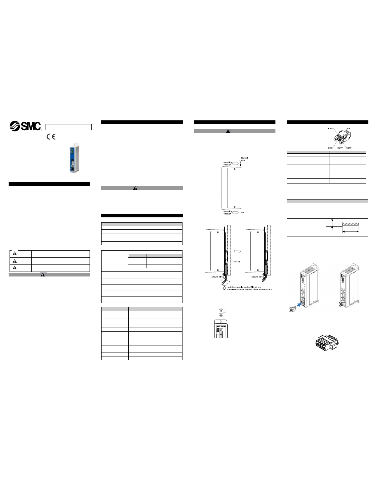
3.1.1 Mounting
The controller can be direct mounted using screws or mounted on a
DIN rail.
Details of the controller mounting options are shown below.
[1] Thread mounting (JXCL17-#) - Mounting with two M4 screws
[2] DIN rail mounting (JXCL18-#) -Mounting with DIN rail
Before locked onto DIN rail
Locked onto DIN rail
3.1.2 Grounding
Install the grounding cable w ith crimped terminal between the M4
screw and shakeproof washer as shown below and tighten the
screw.
3.1.3 Power Supply Connector
•PWR: Pow er supply plug specifications
The specifications of the power supply plug supplied with the controller
are shown below.
3 Installation - continued
Power supply plug (JXC-CPW)
Pin N o.
Terminal
Functi on
Functi on
1
C24V
Power supply (+)
Positiv e control power.
2
M24V
Motor power (+)
Positiv e power for the act uator
motor to be supplied v ia the
controller.
3
EMG
Stop (+)
Positiv e power for Stop signal
4
0V
Common power (-)
Negativ e common power for M24V,
C24V, EMG and LK R LS.
5 - NC
N/A
6
LK RLS
Unlocking (+)
Positiv e power for lock release.
Equiv alent to Phoenix C ontact: DFMC1, 5/3-ST-LR
Electrical Wiring Specifications
Prepare the electrical wiring according to the following specifications (to
be prepared by the user).
Item
Specificati on
Applicable wire size
Single, st randed wire → AW G20 (0.5 mm2) / Max.
length 10 m
The rated temperature of the insulat ion coating
should be 60oC or m ore.
The O.D . should be ø2.5 mm or less .
Stripped wire length
Wire length
10 m or less
After w iring the power supply plug, connect it to the controller PWR
power connector.
Controller
Power supply plug inserted into PWR
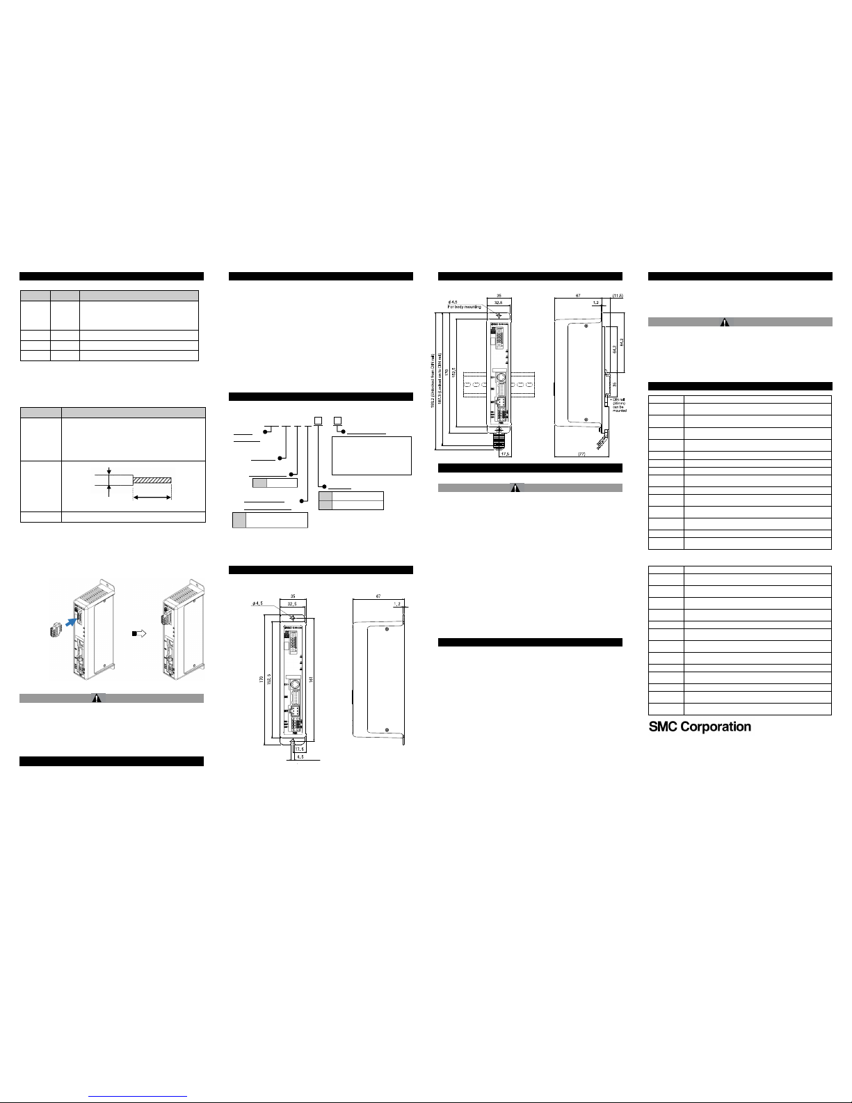
3.1.4 IO-Link Communication Connector
• IO-Link: Communication plug specifications
The specifications of the communication plug (JXC-CL-S) supplied with
the controller are shown below.
Power
supply
plug
To PWR
ORIGINAL INSTRUCTIONS
Refer to Declaration of
Conformity for relevant
Directives
Controller
M4 screw
Cable w ith crimped terminal
Shakeproof washer
JXCL1-SMW16EN
Page 2 of 2
3 Installation - continued
Pin N o.
Terminal
Functi on
1
L+
+24 VDC power supply for IO-Link
communic ation.
IO-Link comm unication start s when the power
supply L+/L- and C24V control power are supplied
to the JXC c ontroller.
2
N.C.
Not connect ed
3
L-
0 VDC power supply for IO-Link com munication
4
C/Q
IO-Link signal.
Phoenix Contact product number: FMC1,5/4-STF-3,5 or equiv alent.
• Electric Wiring Specifications
Prepare the w iring according to the following specifications (to be
prepared by the user).
Descrip tion
Specificati on
Applicable
wire size
Single wire, stranded wire AWG24-16 (0.2-1.5 mm2)
The rated temperature of the insulation coating should be
60oC or m ore. The O.D . should be ø2.5 mm or less .
Conduc tor resistanc e 3 ohms or less
Conduc tor capacitanc e 3 nF or les s
Stripped wire
length
Cable length
20 m or less
After wiring the IO-Link communication plug, connect it to the IO-Link
connector on the controller.
Controller
IO-Link communication plug
3.2 Environment
Warning
Do not use in an environment where corrosive gases, chemicals, salt
water or steam are present.
Do not use in an explosive atmosphere.
Do not expose to direct sunlight. Use a suitable protective cover.
Do not install in a location subject to vibration or impact. Check the
product specifications.
Do not mount in a location exposed to radiant heat.
4 Settings
Initial Setting
•IO-Link master configuration
IODD file
The IODD file is used for mapping the JXC controller to the IO-Link
master.
The IODD file is a device definition file which provides all properties
and parameters required for establishing operation and communication
of the JXC controller.
4 Settings - continued
The IODD includes the main IODD file and a set of image files such as
vendor log, device picture and device icon.
Refer to the operation manual for the IO-Link master for installing the
IODD file.
The IODD file for the JXCL1 can be downloaded from the SMC Web
site.
•URL:http://www.smcworld.com
Documents / Download → Instruction Manuals →
SMC-JXCL17JXCL18_ .zip
•Contents of SMC-JXCL1_v.zip
IODD file: SMC-JXCL17JXCL18- -IODD1.1.xml
Device symbol: SMC-JXCL17JXCL18-pic.png
Device icon: SMC-JXCL17JXCL18-icon.png
Vendor logo: SMC-logo.png
5 How to Order
6 Outline Dimensions (mm)
1) Direct mounting (JXCL17-#)
6 Outline Dimensions (mm) - continued
2) DIN rail mounting (JXCL18-#)
7 Maintenance
7.1 General Maintenance
Caution
Not following proper maintenance procedures could cause the
product to malfunction and lead to equipment damage.
If handled improperly, compressed air can be dangerous.
Maintenance of pneumatic systems should be performed only by
qualified personnel.
Before performing maintenance, turn off the power supply and be
sure to cut off the supply pressure. Confirm that the air is released to
atmosphere.
After installation and maintenance, apply operating pressure and
power to the equipment and perform appropriate functional and
leakage tests to make sure the equipment is installed correctly.
If any electrical connections are disturbed during maintenance,
ensure they are reconnected correctly and safety checks are carried
out as required to ensure continued compliance with applicable
national regulations.
Do not make any modification to the product.
Do not disassemble the product, unless required by installation or
maintenance instructions.
8 Limitations of Use
8.1 Limited warranty and Disclaimer/Compliance Requirements
The product used is subject to the following “Limited warranty
and Disclaimer” and “Compliance Requirements”. Read and
accept them before using the product.
Lim ited warranty and Disclaimer
1) The warranty period of the product is 1 year in service or 1.5 years
after the product is delivered, whichever is f irst
(1)
. Also, the product
may have specified durability, running distance or replacement parts.
Please consult your nearest sales branch.
2) For any failure or damage reported w ithin the warranty period
which is clearly our responsibility, a replacement product or
necessary parts will be provided.
This limited warranty applies only to our product independently, and
not to any other damage incurred due to the failure of the product.
3) Prior to using SMC products, please read and understand the
warranty terms and disclaimers noted in the specified catalogue for
the particular products.
(1)
Vacuum pads are excluded from this 1 year warranty.
A vacuum pad is a consumable part, so it is warranted for a year after
it is delivered. Also, even within the warranty period, the wear of a
product due to the use of the vacuum pad or failure due to the
deterioration of rubber material are not covered by the limited
warranty.
Com pliance Requirements
1) The use of SMC products with production equipment for the
manufacture of w eapons of mass destruction (WMD) or any other
weapon is strictly prohibited.
8 Limitations of Use - continued
2) The exports of SMC products or technology from one country to
another are governed by the relevant security laws and regulations of
the countries involved in the transaction. Prior to the shipment of a
SMC product to another country, assure that all local rules governing
that export are known and followed.
Caution
SMC products are not intended for use as instruments for legal
metrology.
Measurement instruments that SMC manufactures or sells have not
been qualified by type approval tests relevant to the metrology
(measurement) laws of each country.
Therefore, SMC products cannot be used for business or certification
ordained by the metrology (measurement) laws of each country.
9 Contacts
AUSTRIA
SMC Pneumatik GmbH, Girakstras se 8, AT-2100 Korneuburg
BELGIUM
SMC Pneumatic s N.V. ⁄ S.A. Nijverheids straat 20, B-2160
Wommelgem
BULGARIA
SMC Indust rial Automat ion Bulgaria EOOD, Business Park Sof ia,
Building 8-6t h f loor, BG-1715 Sof ia
CROATIA
SMC Indust rijskaAutom atikad.o. o. ZagrebačkaAv enija 104,10
000 Zagreb
CZECH REP.
SMC Indust rial Automat ion CZ s. r.o. Hudcov a 78a, CZ-61200
Brno
DENMARK
SMC Pneumatik A ⁄ S,Egesk ovv ej 1, DK-8700 Horsens
ESTONIA
SMC Pneumatic s Est onia Oü,Laki 12, EE-10621 Tallinn
FINLAND
SMC Automat ion Oy , PL72, Tiistinniitynt ie 4, SF-02031 Es poo
FRANCE
SMC France, 1, Boulev ard de Stras bourg, Parc Gust ave Eif f el,
Bussy Saint Georges, F -77607 Marne La ValleeCedex 3
GERMANY
SMC Deuts chland GmbH , Boschring 13-15, 63329 Egelsbach
GREECE
SMC Italia Hellas Branch, Anagenniseos 7-9-P.C. 14342
N.Philadelphia, Athens
HUNGARY
SMC Hungary IpariAutomat izálásiKft .Torbágy u. 19, HU-2045
Törökbálint
IRELAND
SMC Pneumatic s (Ireland) Ltd.2002 C ity west Business Cam pus,
Naas Road, Saggart, C o. Dublin
ITALY
SMC Italia S.p.A.Via Garibaldi 62, I -20061Carugate, (Milano)
LATVIA
SMC Pneumatic s Latv ia SIA, Dzelzav as str. 120g, Riga, LV1021,
LITHUANIA
UAB “SMC Pneum atics”, Oslo g. 1, LT-04123 Vilnius
NETHERLANDS
SMC Pneumatic s B.V. De Ruy terkade 120, NL-1011 AB
Amsterdam
NORWAY
SMC Pneumatic s Norway AS, Vollsv eien 13 C,
Granfos Næringspark, N-1366 Ly saker
POLAND
SMC Indust rial Automat ion, Polska Sp z o.o.
02-826 W arszawa, ul. Poloneza 89
PORTUGAL
SMC Sucursal Portugal, S. A.Rua D e Eng Ferrerira Dias 452
4100-246, Porto
ROMANIA
SMC Romania S.r.l. StrF runzei 29, Sect or 2, Bucharest
RUSSIA
SMC Pneumatik LLC. Busines s cent re, building 3, 15
Kondratjev skij prospect , St.Peters burg, 195197
SLOVAKIA
SMC Priemy selnáAutom atizáciaSpols.r. o. Fantransk á 1223,
Teplickanadv ahom, 01301
SLOVENIA
SMC Indust rijskaAv tomat ikad.o.o. Mirnskacesta 7, SLO-8210
Trebnje
SPAIN
SMC España S.A. Zuazobidea 14, 01015 Vitoria
SWEDEN
SMC Pneumatic s Sweden AB,Ekhagsv ägen 29-31, SE-141 71
Segeltorp
SWITZERLAND
SMC Schweiz AG,Dorf st rasse 7, Postf ach, 8484 Weisslingen,
TURKEY
SMC Pnömatik SanayiTicaretv eServ is A.Ş. GülbaharCaddesi,
Aydın Plaza, No: 9 ⁄ 4 Güneşli – 34212 , I stanbul
UK
SMC Pneumatic s (U. K.) Ltd. Vincent Avenue, Crownhill, Milton
Keynes , Buckinghams hire MK8 0AN
URL :
http// www.smcworld.com (Global) http// www.smceu. com (Europe)
'SMC Corporation, Akihabar a UDX15F, 4-14-1, Sotokanda, Chiy oda-ku, Tokyo
101 0021
Specif ications are subject to change without prior notice f rom the manufacturer.
© 2018 SMC Corporat ion All Rights Res erved.
Template DKP50047-F-085G
IO-Link
communication
plug
To IO-Link
communication
connector
JX C L 1 -
Electric
equipment
Controller type
L
IO-Link
Number of axis/
Power supply type
Actuator Model
(Enter the actuator model and
include "stroke"
E.g. LEFS16B-100B-S1CL17,
input “LEFS16B-100”)
Controller
Mounting
7
Direct mounting
8
DIN rail
1
1 axis, Power supply
(24VDC)
For mount ing
8-10 mm
ϕ2.5 mm or less
For mount ing
 Loading...