

Page 1
No.SFOD-OMT0010-B
Product name
4-axis Step Motor Controller
(Parallel I/O type)
MODEL/ Series/ Product Number
JXC73/83 Series
Page 2

- 1 -
No.SFOD-OMT0010-B
Contents
1. Safety Instructions ........................................................................ 5
2. Product Outline .............................................................................. 7
2.1 Features ............................................................................................................ 7
2.2 How to Order .................................................................................................. 8
2.3 Product configuration ............................................................................... 9
3. Procedures to Trial run ............................................................... 10
3.1 Checking the contents of the package .......................................... 10
3.2. Mounting the controller ........................................................................ 11
3.3 Install the setting software and the driver ................................... 11
3.4 Wiring and connection ............................................................................ 11
3.5 Power supply, Start-up of controller setting software, and Alarm check 11
(1) Supplying power ................................................................................ 11
(2) Start-up of controller setting software .................................. 12
(3) Alarm check.......................................................................................... 13
3.6 Parameters and Step data ..................................................................... 14
(1) Select the actuator............................................................................ 14
(2) Setting parameters ........................................................................... 17
(3) Step data settings ............................................................................. 19
3.7 Check using JOG operation ................................................................ 20
(1) Change to Remote mode .............................................................. 20
(2) Return to origin .................................................................................. 21
(3) JOG or Inching ................................................................................... 22
3.8 Operation test using Test Drive ......................................................... 23
(1) Test Drive setting .............................................................................. 23
(2) Change to Remote mode .............................................................. 23
(3) Return to origin .................................................................................. 24
(4) Test drive starts ................................................................................. 24
4. Product Specifications ................................................................ 25
4.1 Basic Specifications ................................................................................ 25
4.2 Parts Description ....................................................................................... 26
4.3 Dimensions ................................................................................................... 27
(1) Direct mounting ................................................................................... 27
(2) DIN rail mounting .............................................................................. 27
4.4 Mounting ........................................................................................................ 28
(1) Mounting ................................................................................................ 28
(2) Grounding ............................................................................................. 29
Page 3

- 2 -
No.SFOD-OMT0010-B
(3) Mounting location ............................................................................. 30
5. Power supply connector ............................................................. 31
5.1 Connector specifications ...................................................................... 31
(1) Main control power supply connector: C PWR ................. 31
(2) Motor drive power connector: M PWR ................................... 31
(3) Motor control power supply connector: CI ......................... 32
5.2 Wiring ............................................................................................................... 33
(1) Wiring of the power supply connector .................................. 33
(2) Wiring of the stop switch .............................................................. 34
6. Details of parallel I/O connector ................................................. 36
6.1 Parallel I/O specifications ..................................................................... 36
6.2 Parallel I/O circuit (NPN, PNP) ............................................................ 36
(1)Parallel I/O input circuit ................................................................... 36
(2)Parallel I/O output circuit ............................................................... 37
6.3 Parallel I/O signals .................................................................................... 38
(1) I/O1 ............................................................................................................ 39
(2) I/O2 ............................................................................................................ 42
6.4 Parallel I/O Wiring Example.................................................................. 44
(1) NPN type ................................................................................................ 44
(2) PNP type ................................................................................................. 46
7. Setting Data Entry ....................................................................... 48
7.1 Profile parameter ....................................................................................... 48
7.2 Basic parameter ......................................................................................... 49
7.3 Return to origin parameter ................................................................... 51
7.4 Step data ........................................................................................................ 52
(1) ABS ........................................................................................................... 54
(2) INC ............................................................................................................. 54
(3) LIN-A / LIN-I........................................................................................... 54
(4) CIR-R / CIR-L ........................................................................................ 55
(5) SYN-I ........................................................................................................ 55
8. Description of operation ............................................................. 56
8.1 Return to origin ........................................................................................... 56
8.2 Positioning Operation ............................................................................. 57
8.3 Pushing Operation .................................................................................... 60
8.4 Linear interpolation .................................................................................. 64
8.5 Circular interpolation ............................................................................... 67
8.6 Speed tuning control ..................................................................................... 71
8.7 Controller input signal response time............................................ 73
Page 4

- 3 -
No.SFOD-OMT0010-B
8.8 Methods of interrupting operation ................................................... 73
9. Operation Instructions ................................................................ 74
9.1 Outline of the Operation instruction ............................................... 74
9.2 Operation procedure of parallel I/O signals ................................ 74
(1) From power on to Return to origin .......................................... 74
(2) Positioning operation ..................................................................... 75
(3) Pushing operation .................................................................................. 76
(4) HOLD ........................................................................................................ 77
(5) RESET ..................................................................................................... 77
(6) STOP ......................................................................................................... 79
(7) Area output ........................................................................................... 80
10. Accessories ................................................................................ 81
10.1 Power cable for main control ............................................................ 81
10.2 DIN rail mounting bracket................................................................... 81
10.3 Actuator cable (5m or less) ................................................................ 82
10.4 Actuator cable (8-20m) ......................................................................... 82
10.5 Actuator cable [For sensor/ with lock (5m or less)] ............. 83
10.6 Actuator cable [For sensor/ with lock (8m to 20m)] ............. 83
10.7 ParallelI/O cable......................................................................................... 84
10.8 Controller Set up kit ............................................................................... 85
11. Alarm detection .......................................................................... 86
11.1 Parallel output Alarm group .............................................................. 86
11.2 Alarms and countermeasures .......................................................... 87
12. Common Precautions for wiring and cable ............................ 95
13. Electric Actuators / Common Precautions .............................. 96
13.1 Design and Selection ............................................................................ 96
13.2 Mounting ...................................................................................................... 97
13.3. Handling Precautions .......................................................................... 98
13.4 Operating environment ........................................................................ 99
13.5 Maintenance and Precautions ....................................................... 100
13.6 Precautions for actuator with lock ............................................. 100
14. Controller and Peripheral Devices / Specific Product Precautions 101
14.1 Design and selection .......................................................................... 101
14.2 Handling Precautions ........................................................................ 101
14.3 Mounting ................................................................................................... 103
14.4 Wiring ......................................................................................................... 103
Page 5

- 4 -
No.SFOD-OMT0010-B
14.5 Power supply .......................................................................................... 104
14.6 Grounding ................................................................................................ 104
14.7 Maintenance ............................................................................................ 104
15. Troubleshooting ...................................................................... 105
15.1 Operation Errors ................................................................................... 105
15.2 Position / Speed problems .............................................................. 108
Supplement 1. Actuator Specifications ........................................ 110
Supplement 1.1 Initial setting of LEY/LEYG series ................................. 110
Supplement 1.2 Initial setting of LEFS series ............................................ 110
Supplement 1.3 Initial setting of LES(H) series ............................. 111
Supplement 1.4 Initial setting of LEP series .................................... 111
Supplement 1.5 Initial setting of LEFB series ................................. 112
Supplement 1.6 Initial setting of LER series ................................... 112
Supplement 1.7 Initial setting of LEH series ................................... 112
Page 6
- 5 -
No.SFOD-OMT0010-B
JXC73/83 Series / Controller
1. Safety Instructions
These safety instructions are intended to prevent hazardous situations and/or equipment damage.
These instructions indicate the level of potential hazard with the labels of “Caution,” “Warning” or
“Danger.”
They are all important notes for safety and must be followed in addition to International Standards
(ISO/IEC)*1) , and other safety regulations.
*1) ISO 4414: Pneumatic fluid power -- General rules relating to systems.
ISO 4413: Hydraulic fluid power -- General rules relating to systems.
IEC 60204-1: Safety of machinery -- Electrical equipment of machines .(Part 1: General requirements)
ISO 10218-1992: Manipulating industrial robots -Safety.
etc.
Caution
Caution indicates a hazard with a low level of risk which, if not avoided, could result in minor or
moderate injury.
Warning
Warning indicates a hazard with a medium level of risk which, if not avoided, could result in
death or serious injury.
Danger
Danger indicates a hazard with a high level of risk which, if not avoided, will result in death or
serious injury.
Warning
1. The compatibility of the product is the responsibility of the person who designs the equipment or
decides its specifications.
Since the product specified here is used under various operating conditions, its compatibility with specific
equipment must be decided by the person who designs the equipment or decides its specifications based on
necessary analysis and test results.
The expected performance and safety assurance of the equipment will be the responsibility of the person who
has determined its compatibility with the product.
This person should also continuously review all specifications of the product referring to its latest catalog
information, with a view to giving due consideration to any possibility of equipment failure when configuring the
equipment.
2. Only personnel with appropriate training should operate machinery and equipment.
The product specified here may become unsafe if handled incorrectly.
The assembly, operation and maintenance of machines or equipment including our products must be
performed by an operator who is appropriately trained and experienced.
3. Do not service or attempt to remove product and machinery/equipment until safety is confirmed.
1.The inspection and maintenance of machinery/equipment should only be performed after measures to
prevent falling or runaway of the driven objects have been confirmed.
2.When the product is to be removed, confirm that the safety measures as mentioned above are implemented
and the power from any appropriate source is cut, and read and understand the specific product precautions
of all relevant products carefully.
3. Before machinery/equipment is restarted, take measures to prevent unexpected operation and malfunction.
4. Contact SMC beforehand and take special consideration of safety measures if the product is to
be used in any of the following conditions:
1. Conditions and environments outside of the given specifications, or use outdoors or in a place exposed to
direct sunlight.
2. Installation on equipment in conjunction with atomic energy, railways, air navigation, space, shipping,
vehicles, military, medical treatment, combustion and recreation, or equipment in contact with food and
beverages, emergency stop circuits, clutch and brake circuits in press applications, safety equipment or
other applications unsuitable for the standard specifications described in the product catalog.
3. An application which could have negative effects on people, property, or animals requiring special safety
analysis.
4.Use in an interlock circuit, which requires the provision of double interlock for possible failure by using a
mechanical protective function, and periodical checks to confirm proper operation.
Page 7

- 6 -
No.SFOD-OMT0010-B
JXC73/83 Series / Controller
1. Safety Instructions
Caution
1.The product is provided for use in manufacturing industries.
The product herein described is basically provided for peaceful use in manufacturing industries.
If considering using the product in other industries, consult SMC beforehand and provide specifications
or a contract, if necessary.
If anything is unclear, contact your nearest sales branch.
Limited warranty and Disclaimer/Compliance Requirements
The product used is subject to the following “Limited Warranty and Disclaimer” and “Compliance
Requirements”.
Read and accept them before using the product.
Limited warranty and Disclaimer
1.The warranty period of the product is 1 year in service or 1.5 years after the product is
delivered,whichever is first. *2)
Also, the product may have specified durability, running distance or replacement parts. Please
consult your nearest sales branch.
2. For any failure or damage reported within the warranty period which is clearly our responsibility,
a replacement product or necessary parts will be provided.
This limited warranty applies only to our product independently, and not to any other damage
incurred due to the failure of the product.
3. Prior to using SMC products, please read and understand the warranty terms and disclaimers
noted in the specified catalog for the particular products.
2) Vacuum pads are excluded from this 1 year warranty.
A vacuum pad is a consumable part, so it is warranted for a year after it is delivered.
Also, even within the warranty period, the wear of a product due to the use of the vacuum
pad or failure due to the deterioration of rubber material are not covered by the limited
warranty.
Compliance Requirements
1. The use of SMC products with production equipment for the manufacture of weapons of mass
destruction (WMD) or any other weapon is strictly prohibited.
2. The exports of SMC products or technology from one country to another are governed by the
relevant security laws and regulation of the countries involved in the transaction. Prior to the
shipment of a SMC product to another country, assure that all local rules governing that export
are known and followed.
Page 8
- 7 -
No.SFOD-OMT0010-B
2. Product Outline
2.1 Features
This controller uses predefined "step data" in which multiple data such as position or speed are
included together as operation instructions to the actuator. An external PLC specifies the step data
number to the controller and will start the operation based on the step data.
Feature of the controller.
4 axes speed tuning control
Up to 4 axes speed tuning control is available for specifying step data.
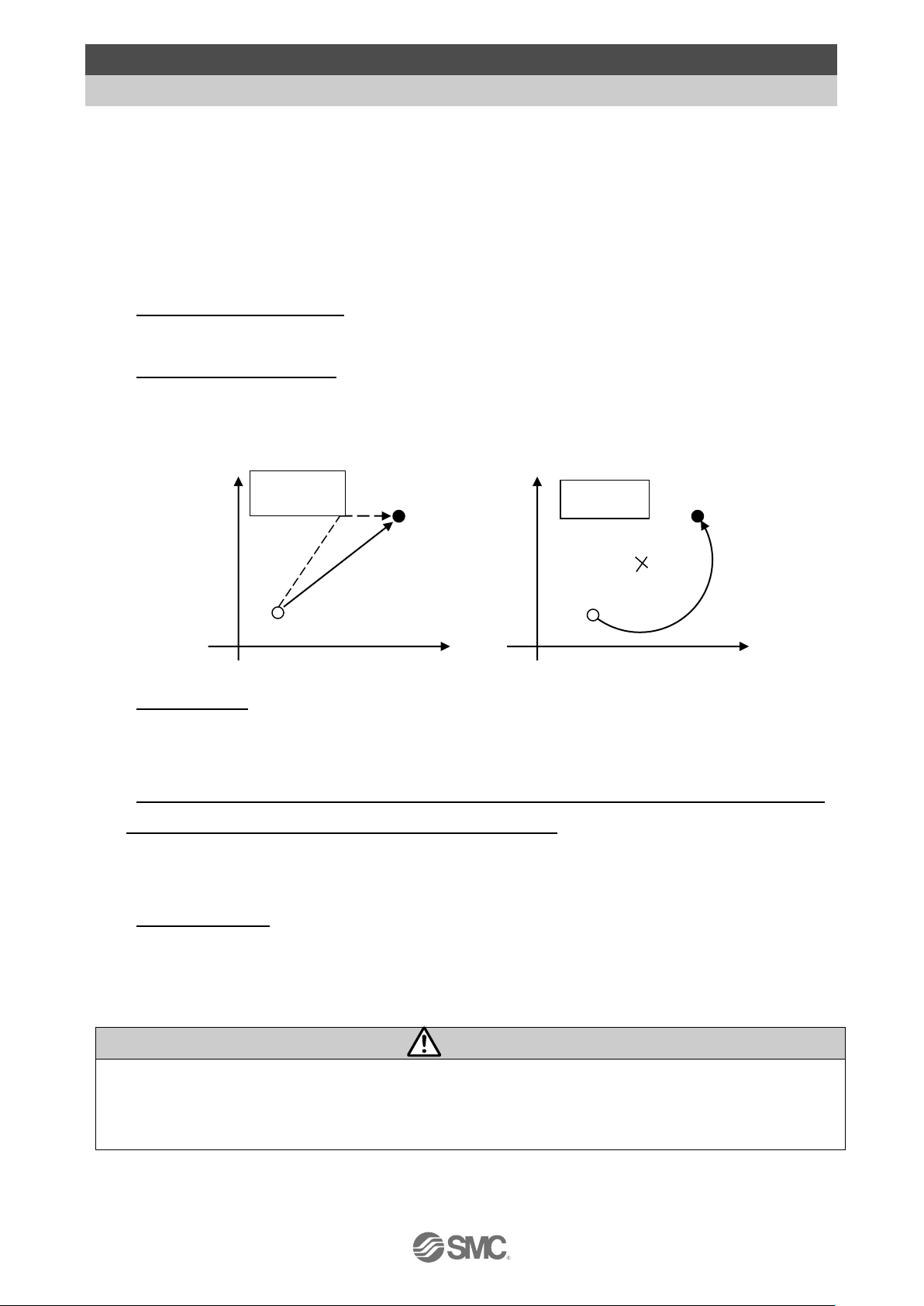
Linear/ circular interpolation
Linear interpolation for up to 3 axes and circular interpolation between 2 axes are possible.
Linear interpolation is possible by setting the target position and travel speed of the locus. For
circular interpolation, the travel speed of the locus and the centre position must be set.
Return to origin
All axes are possible to return to origin by using one “return to origin” signal (SETUP). The
order of the return to origin operation is possible to specify by the parameters.
It is possible to set 512 steps of positioning or pushing operation in normal mode, and 2048
steps of positioning or pushing operation in extended mode.
Control the actuator according to the step data specified by the input of parallel I/O. It is
possible to operate all axes by using 1 step.
Data input method
It is possible to set the step data, parameters, monitor conditions, and reset alarms by
communication via the USB port from a PC inwhich the controller setting software is installed.
Caution
Please keep this manual safe for future use. It will be necessary to refer to this manual along with the
operation manuals for other actuators and controller setting software at installation and fault finding.
Keep this operation manual accessible for reference.
Circular
interpolation
Current
position
Target
position
Center
Linear
interpolation
Current position
Target position
Linear interpolation
Individual
operation of
the axis
Page 9
- 8 -
No.SFOD-OMT0010-B
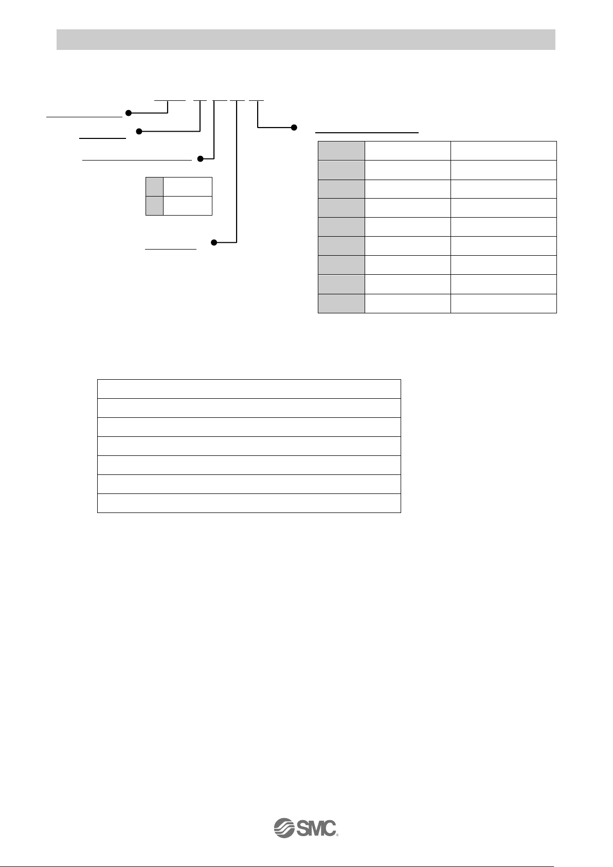
2.2 How to Order
How to order is shown below.
Applicable Actuator
Electric Actuator Rod Type LEY Series
Electric Actuator Rod Type with Guide LEYG Series
Electric Actuator Slider Type LEF Series
Electric Slide Table LES/LESH Series
Electric Rotary Table LER Series
Note2)
Electric Actuator Miniature Type LEPY/LEPS Series
Electric Gripper (2-Finger Type, 3-Finger Type) LEH Series
Note 2) The continuous rotation (360°) type is excluded.
J X C 3
I/O cable or mounting
Input/Output specifications
Controller
4 axis type
Electric equipment
7
NPN
8
PNP
Symbol
I/O cable
Note1)
Mounting
1
1.5m
Direct mounting
2
1.5m
DIN rail
3
3m
Direct mounting
4
3m
DIN rail
5
5m
Direct mounting
6
5m
DIN rail
7
--
Direct mounting
8
--
DIN rail
Note 1) When I/O cable (1.5 to 5m) is selected,
two I/O cables are included.
Page 10
- 9 -
No.SFOD-OMT0010-B
●Motor control power
supply connector
(Accessory)
<Applicable wire size>
AWG20 (0.5mm2)
● Motor drive power connector
(Accessory)
<Applicable wire size>
AWG16 (1.25mm2)
PC
● USB cable
Product No.: JXC-W1-2
位置 速度
100 500
200
1000
50
200
1
2
3
テスト
テスト
テスト
現在位置
120.3
現在速度
200
mm
mm/s
動作中
アラーム
モニタ
設定
位置 速度
100 500
200
1000
50
200
1
2
3
テスト
テスト
テスト
現在位置
120.3
現在速度
200
mm
mm/s
動作中
アラーム
モニタ
設定
●Controller set up kit
Contents
-Controller Setting Kit
-USB cable
Product No.: JXC-W1
PLC
Main control power
supply 24VDC
Motor control and
motor drive power
supply
24 VDC
●Power cable for main control
Cable length: 1.5m (Accessory)
Product No.: JXC-C1
Note2)
Note2)
Note2)
Note2)
●Controller setting software
Product No.: JXC-W1-1
Input/output
signal power
supply
24VDC
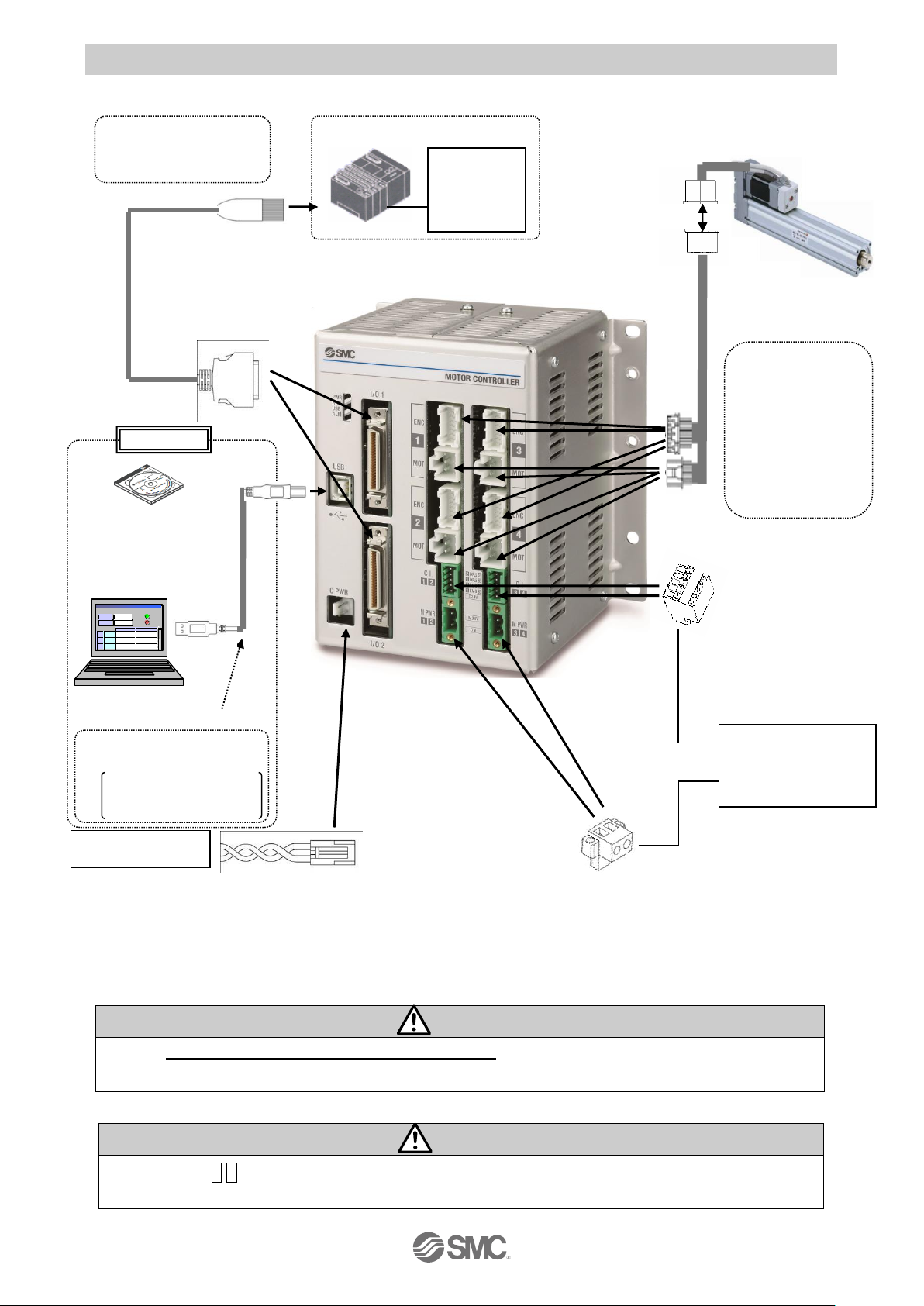
2.3 Product configuration
Structure of the controller.
Note 1) Connected actuators should be ordered separately.
Note 2) PLC, PC and 24VDC power supply should be prepared by theuser.
Wirning
Refer to 12. Common Precautions for wiring and cable.
Use “USB cable (JXC-W1-2)” when communicating with a PC.
Caution
Connector “CI3 4” must be connected even when axis 3 and 4 are not used. If not, a “Modbus
Error” alarm will be generated.
To M PWR
To I/O
●Controller
● Electric actuator
Note1)
Options
To CI
To ENC
To MOT
● I/O cable
Product No: JXC-C2-
To USB
Note1)
●Actuator cable
Part No:
LE-CP--
(Robotic type cable)
LE-CP---S
(Standard cable)
To C PWR
Page 11
- 10 -
No.SFOD-OMT0010-B
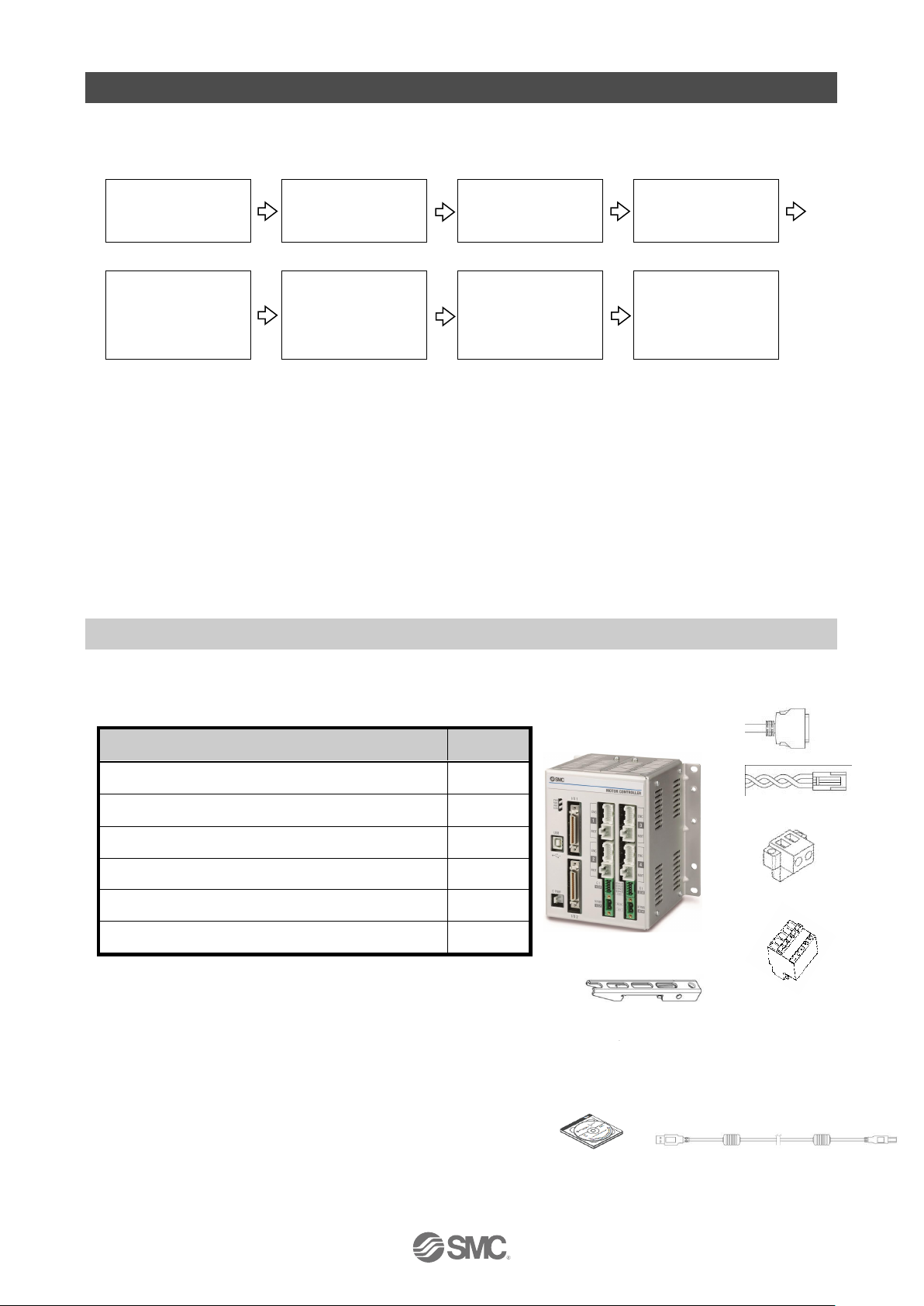
3. Procedures to Trial run
Install, wire, set and perform a trial run for the controller referring to the procedure below when using
the product for the first time.
Check the contents of
the package
Mounting the controller
Software Installation
Wiring and connecting
Supply power.
Start-up of controller
setting software
Parameters and
Step data
Check using JOG
operation
Operation test using
Test Drive.
For “Installation of the software”, refer to this operation manual and the Installation Manual for the
controller setting software (No.SFOD-OMT0008). For “Start-up of controller setting software”,
“Parameters and step data”, “Check using JOG operation” and “Operation test using Test Drive”,
please refer to the setting software operation manual (No.SFOD-OMT0012).
When this controller is used for the first time after purchase, do not upload the default values in the
controller.
Please download the information which has been set by the controller setting software and use it.
3.1 Checking the contents of the package
After unpacking everything, check the description on the label to identify the controller and the
number of accessories.
Note1) These items are included if you ordered by the
part number for a set of controller.
[Options]
Controller setting kit (Product model No.: JXC-W1)
(Controller setting software and USB cable are included.)
If any parts are missing or damaged, please contact your distributor.
Product name
Quantity
Controller (JXC3)
1 pc.
Power cable for main control (Length 1.5m)
1 pc.
Motor drive power connector
2 pcs.
Motor control power supply connector
2 pcs.
DIN rail mounting bracket
Note 1)
1 set
I/O cable
Note1)
2 pcs.
Controller Setting Kit
Controller
Power cable for main control
I/O cable
Note1)
Motor control power supply
connector
Motor drive power connector
USB cable
DIN rail mounting bracket
Note 1)
Mounting screw M5 x8 (4pcs.),
Holding screw M5 x14 (2pcs.) included
Page 12
- 11 -
No.SFOD-OMT0010-B
3.2. Mounting the controller
Refer to
4.4 Mounting
for instructions on how to mount the controller.
3.3 Install the setting software and the driver
Install the controller setting software and driver software on the PC to be used.
For details, refer to the Installation Manual for the controller setting software (No.SFOD-OMT0008).
3.4 Wiring and connection
Connect the cables to the controller.
Refer to section
2.3 Product configuration, 5.2 Wiring
and
6.4 Parallel I/O Wiring Example
for
wiring details.
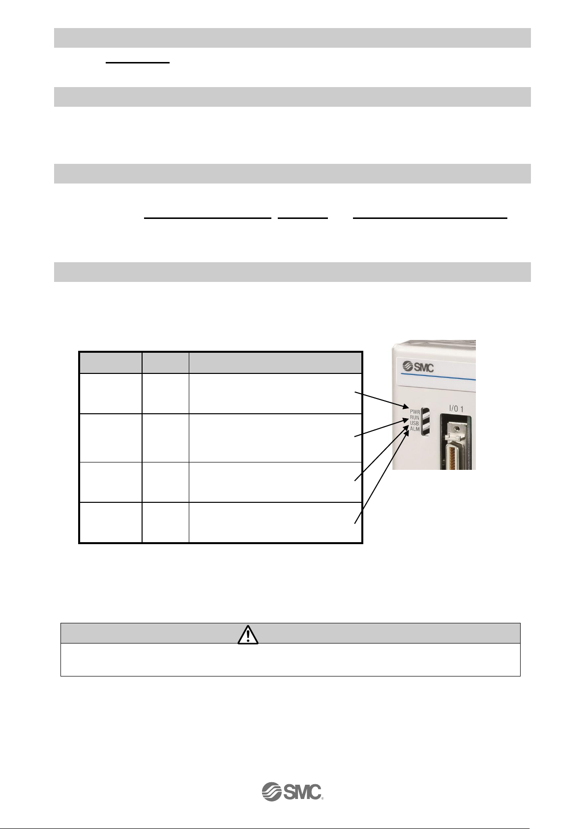
3.5 Power supply, Start-up of controller setting software, and Alarm check
(1) Supplying power
After supplying power for the motor control and motor drive, turn on the power supply for the main
control.
LED
Colour
Status
PWR
Green
ON: Power ON
OFF: Power OFF
RUN
Green
ON: Operating
Flashing: Operation by the setting
software
OFF: Not operated
USB
Green
ON: USB connected
OFF: USB not connected
ALM
Red
ON: Alarm is generated
OFF: Alarm is not generated
Check that thePWR LED is ON.
If the green PWR LED is not ON, check the wiring of the power supply and the power supply
voltage.
Caution
After supplying power for the motor control and motor drive, turn on the power supply for the
main control. Otherwise a“Modbus Error”alarm will be generated.
Page 13
- 12 -
No.SFOD-OMT0010-B
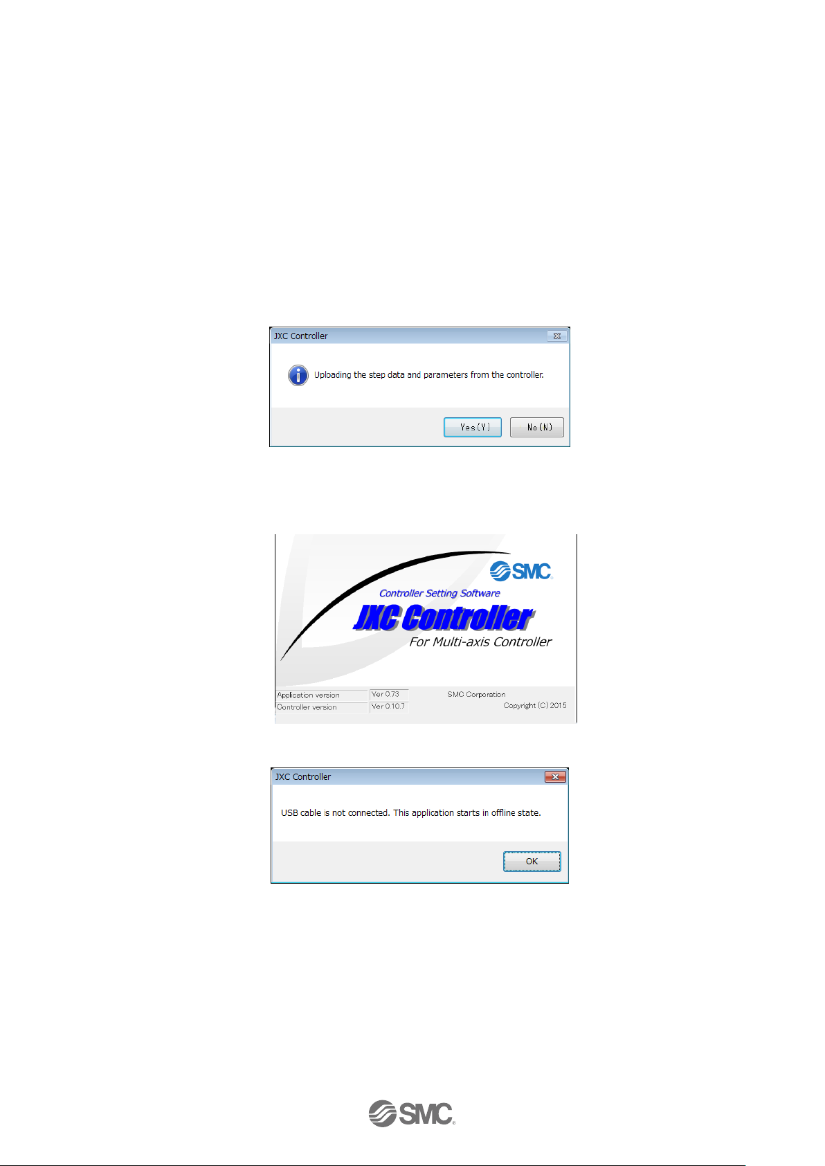
(2) Start-up of controller setting software
Using a PC with the controller setting software installed, start the application “SMC / JXC
Controller” to start the setting software.
If the controller setting software is installed with the default setting, an icon will be created on the
desk top. It is possible to start the setting software by double-clicking the icon.
When the setting software starts, the connection between the controller and PC is confirmed. The
screen below will be displayed when the communication is established correctly.
However, when the setting software is started for the first time, this window will not appear.
When power is supplied to the controller for the first time, the title window will be displayed.
The following window will be displayed after setting the parameters of the controller and the
connected actuator.
When selecting “No (N)”, the controller will start without uploading. The title window shown below
will be displayed.
When the PC is not able to communicate with the controller, the following screen is displayed.
When select “OK”, the title window will be displayed.
Page 14
- 13 -
No.SFOD-OMT0010-B
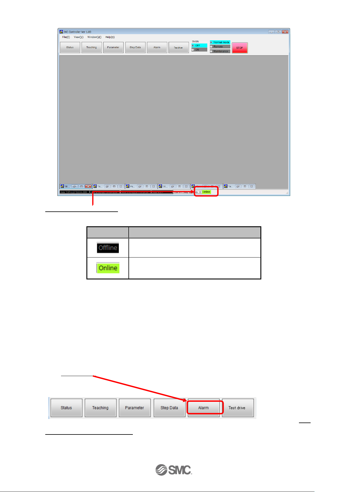
After the initial title window is displayed, the following main window will be displayed.
The communication status between the controller and PC is indicated at the bottom of the main
window.
Display
Details
Off-line state
On-line state
When the PC is able to communicate with the controller, "On-line" status is established
automatically.
If the communication is in the off-line state, the PC is not able to communicate with the controller.
Please check the following.
-
Check that power is supplied to the controller at the correct voltage.
- Check that the controller and the PC are connected to each other via the
communication cable.
- Check that the USB driver is installed correctly.
(3) Alarm check
If the Alarm button at the top of the main window of the setting software flashes red an alarm has
been generated.
It is possible to check the details of the generated alarm by clicking the Alarm button. Refer to
11.2
Alarms and countermeasures
for details of the countermeasures against the alarm, and reset
the alarm.
Page 15
- 14 -
No.SFOD-OMT0010-B
3.6 Parameters and Step data
When using for the first time or after changing the connected actuator, or when the settings of the
controller or connected actuator have been changed, it is necessary to review the set parameters and
step data.
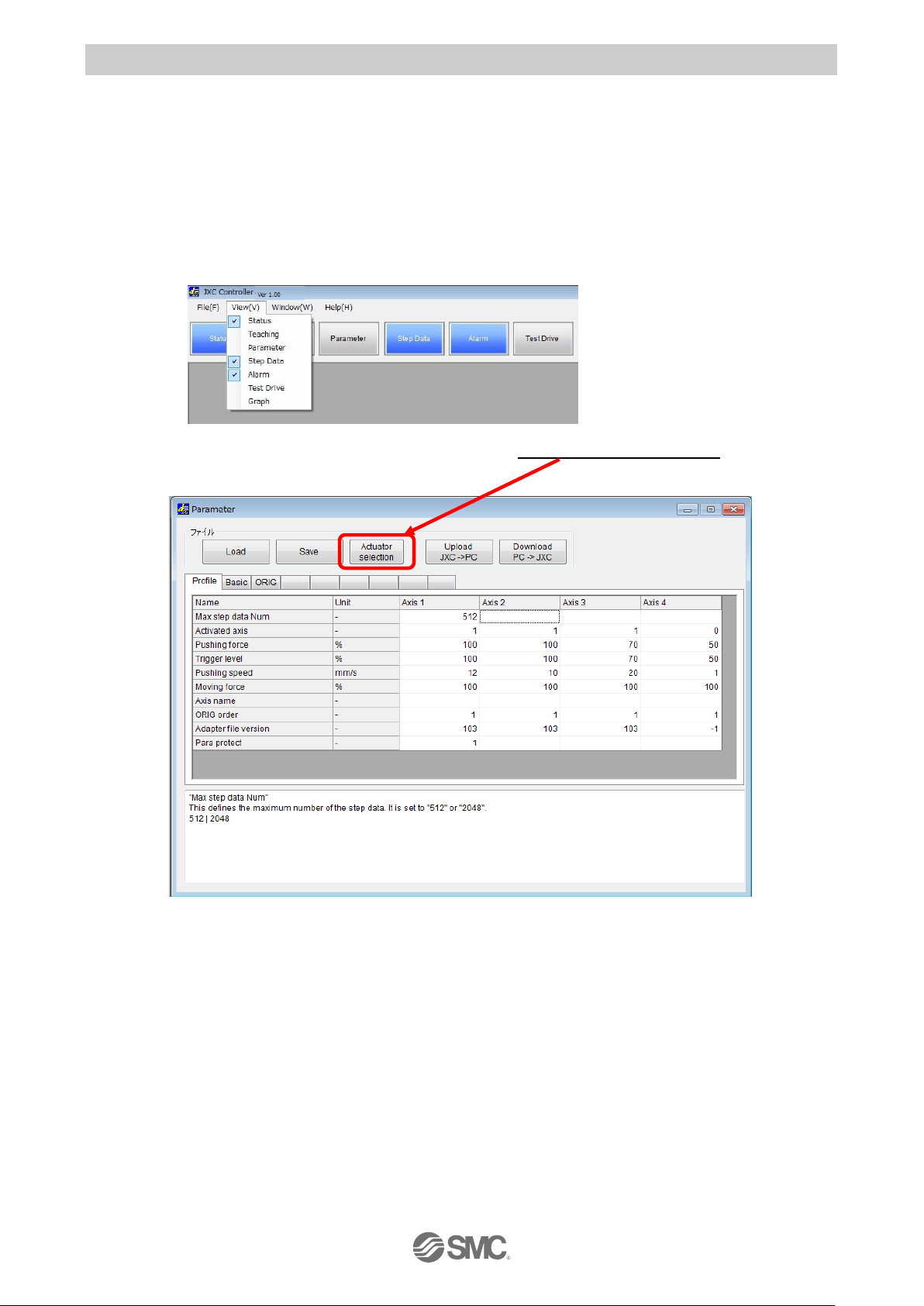
It is possible to display parameters and step data as shown below.
(1) Select the actuator
Select "View(V)" at the top of the main window, and check the parameters.
The Parameter window will be displayed.Select the "Actuator selection" button. The Actuator
selection window will be displayed.
Page 16
- 15 -
No.SFOD-OMT0010-B
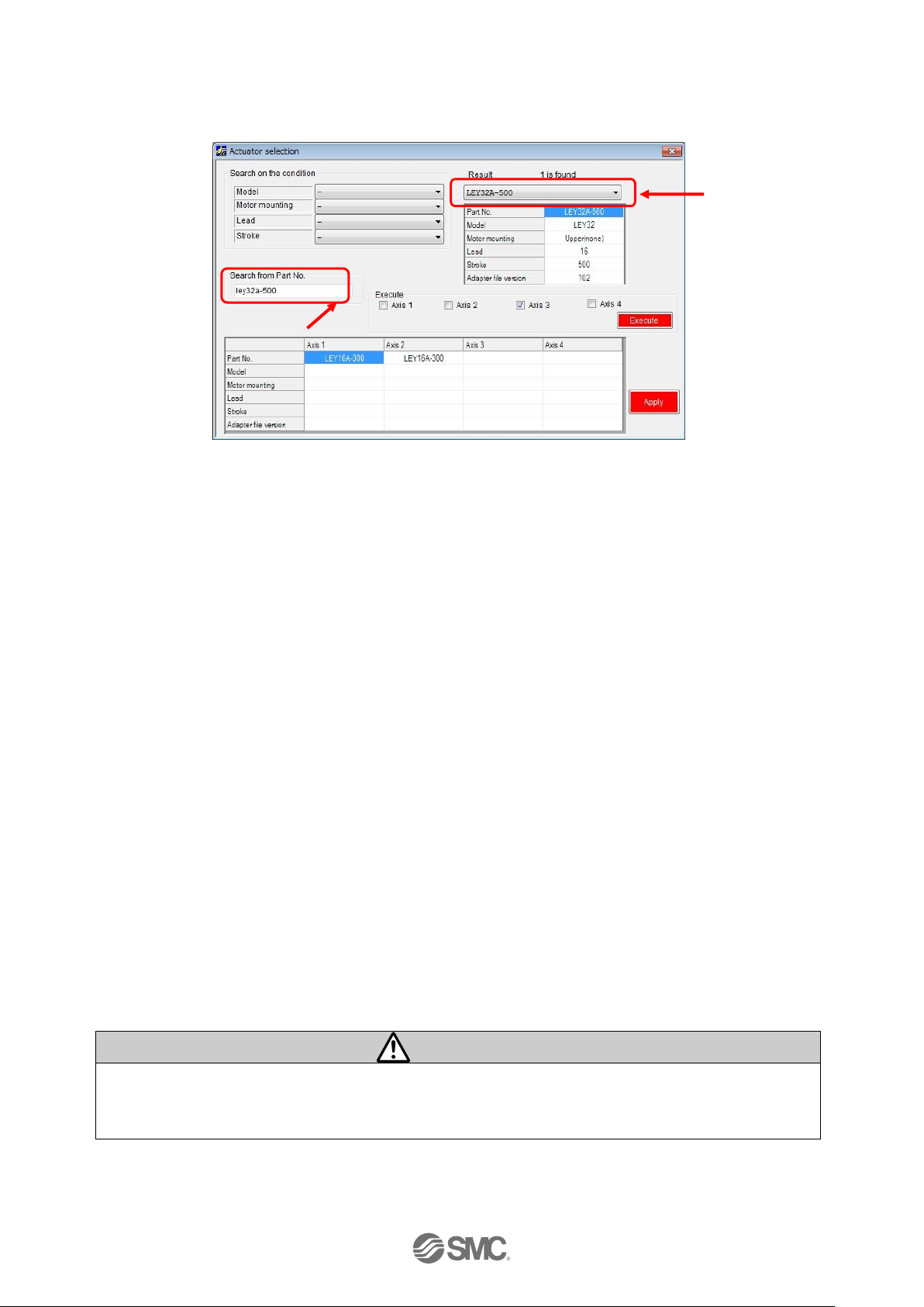
Input the partnumber of the actuator to be used in the “Search from Part No. area”.
A list of part numbers of the actuators matching the conditions will be displayed by clicking the
"Result" button. Select the actuator to be connected.
If the part number of the actuator to be used is already known, input the part number until stroke.
Example) When the LEY16RA-100BML is ordered, input ‘LEY16RA-100’.
When the LER series is used, input the part number including the rotation angle.
Example) When the LERH30K-3L is ordered, input ‘LERH30K-3’.
When there is no match in the results even when the stroke is input, the possible causes could
be :-.
(a) No applicable stroke
Input the part number without the stroke. Select the closest model to the actuator being used,
with a stroke which is longer than that of the actuator being used.
Example) When LEY16RA-75 is ordered, input ‘LEY16RA-100’.
(b) For LEFSH(High precision type)
Input LEFS to search.
Example) When LEFSH25RH-300 isordered, input ‘LEFS25RH-300’
(c) When a Clean type (11-) or Secondary battery type (25A-) is ordered.
Search without inputting 11- or 25A-, and find the actuator to which 11- or 25A- is applicable.
Example) When 11-LEFSH16A-100BR is ordered, input ‘LEFS16A-100’
Caution
When the stroke parameter selected is longer than the stroke of the actuator to be used, the
"position" input to the step data must not exceed the actuator stroke range.
When there is no actuator match, consult SMC.
Search from Part No. area
Result
Page 17
- 16 -
No.SFOD-OMT0010-B
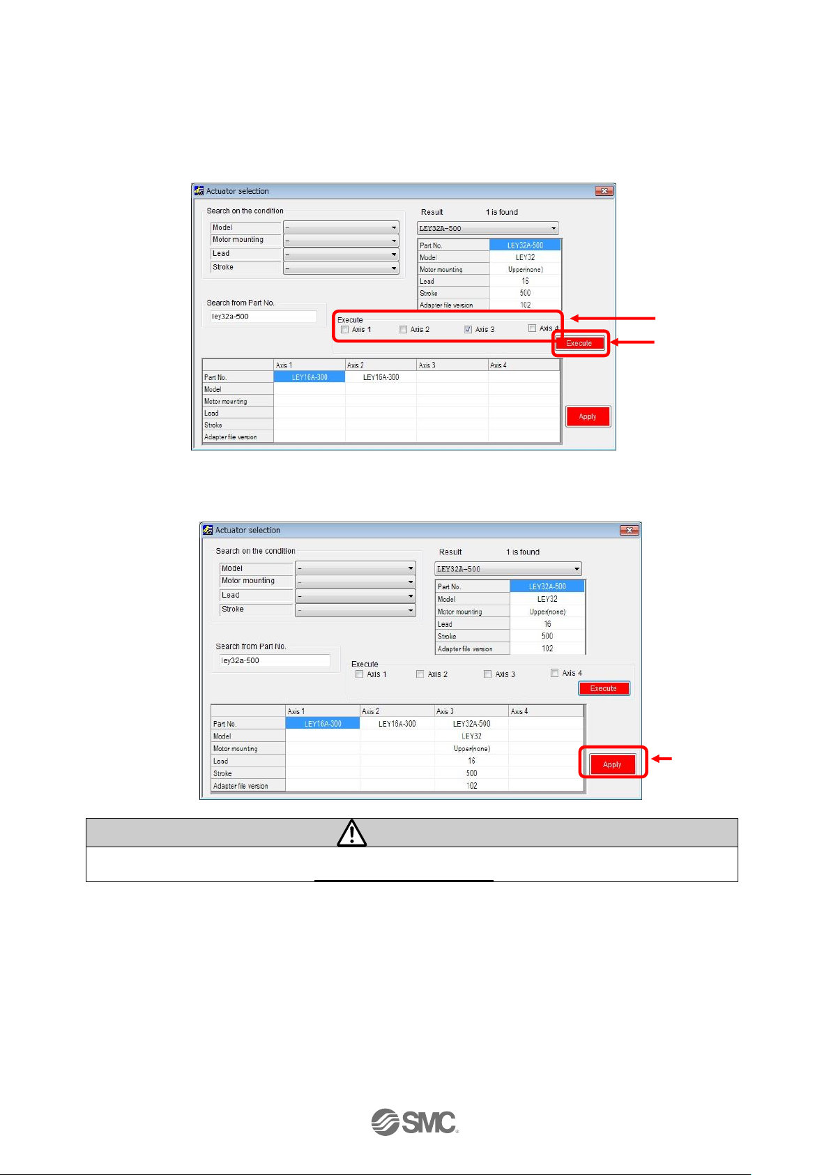
Select the check box for the axis for which parameters are to be input (one or more boxes are
possible to be selected).
Select the "Execute"
button.
Axis parameters will be displayed in the
Actuator selection window. The values input here are for display only, and are not written to
the controller.
Display the parameters for all axes.
Select the "Execute" button.
The parameters are copied to
the parameter window table.
Caution
Copying does not write parameters to the controller. Be sure to download the parameters
following the procedure in section 3.6 (2) Setting parameters.
Check box
Execute
Apply
Page 18
- 17 -
No.SFOD-OMT0010-B
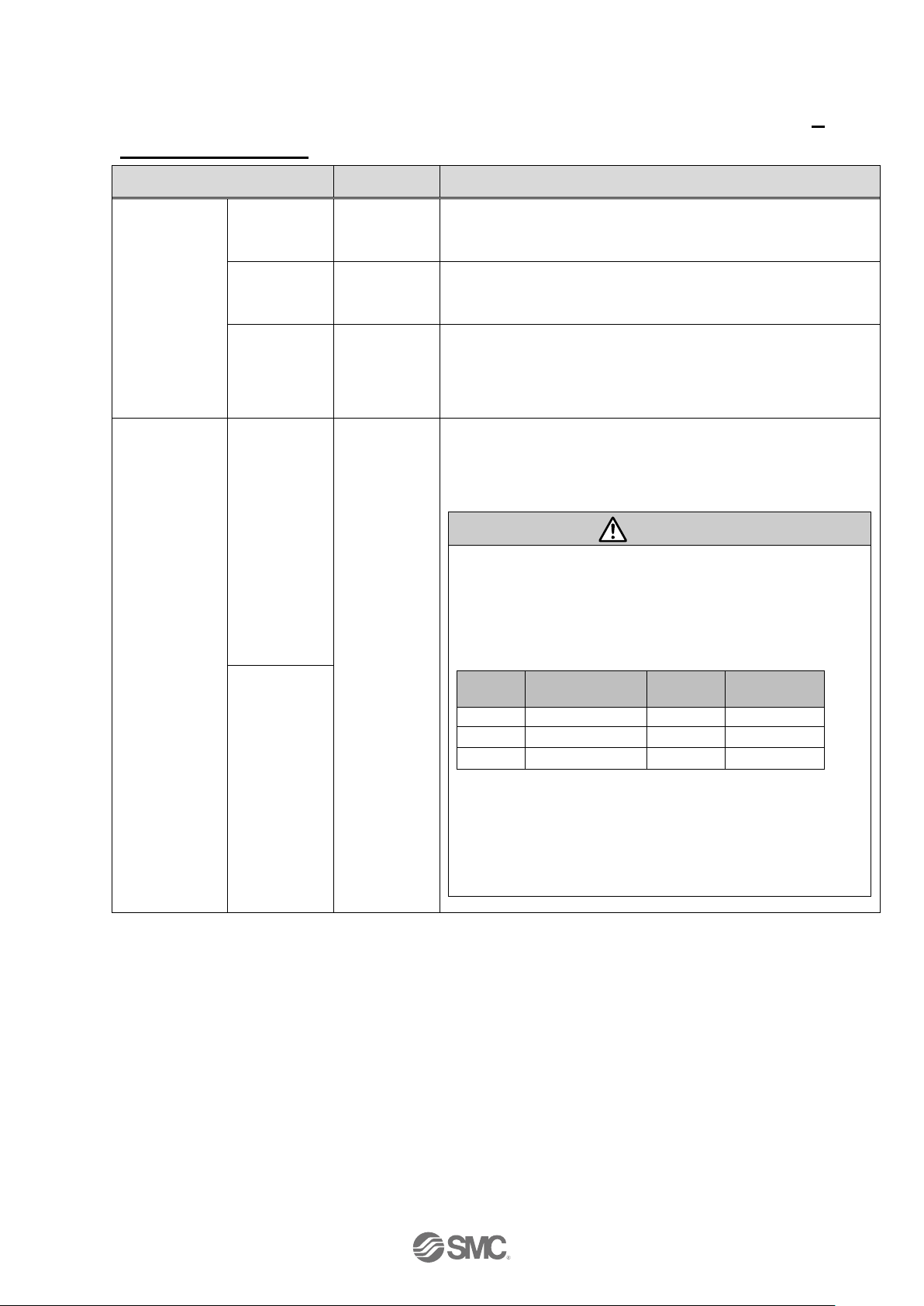
(2) Setting parameters
Set the parameters such as for valid axis and electronic gear.
Check the parameters below and change them if necessary. For other items, refer to section
7.
Settings and Data Entry
.
Parameter name
Input range
Outline
Profile
parameter
Max step
data Num
512 or
2048
Maximum step data. Change if necessary.
Activated
axis
0 or 1
Set the validity of the axes. Set "0" (invalid) when no
actuator is connected. Set "1" (valid) when connected.
ORIG
order
1 to 4
The order for axes to return to origin. The order is assigned
from 1 to 4. Multiple axes are possible to return to origin
simultaneously by setting the same order number.
Basic
parameter
Undefined
No.11
1 to 4096
Define the Electronic Gear.
Undefined parameter No.11: Electronic gear (numerator)
Undefined parameter No.12: Electronic gear (denominator)
Caution
When interpolation is performed for actuators of
different lead, the travel distance per pulse must be the
same. Otherwise do not change the distance.
Set the electronic gear for Axis 2, 3 or 4 so that the travel
distance for all of them are the same as Axis 1.
[Setting example]
Axis
Actuator
Lead
Electronic
gear ratio
Axis 1
LEY16C-300
2.5mm
1/ 1
Axis 2
LEY16B-300
5mm
25/ 50
Axis 3
LEY16A-300
10mm
25/ 100
Set Axis 2 and 3 so that the travel distance becomes
2.5mm per 800 pulse.
Electronic Gear ratio
= Lead of Axis 1/ Lead of Axis 2(or Axis 3)
=2.5mm/5mm (or 2.5mm/10mm)
=25/50 (or 25/100)
Undefined
No.12
Page 19
- 18 -
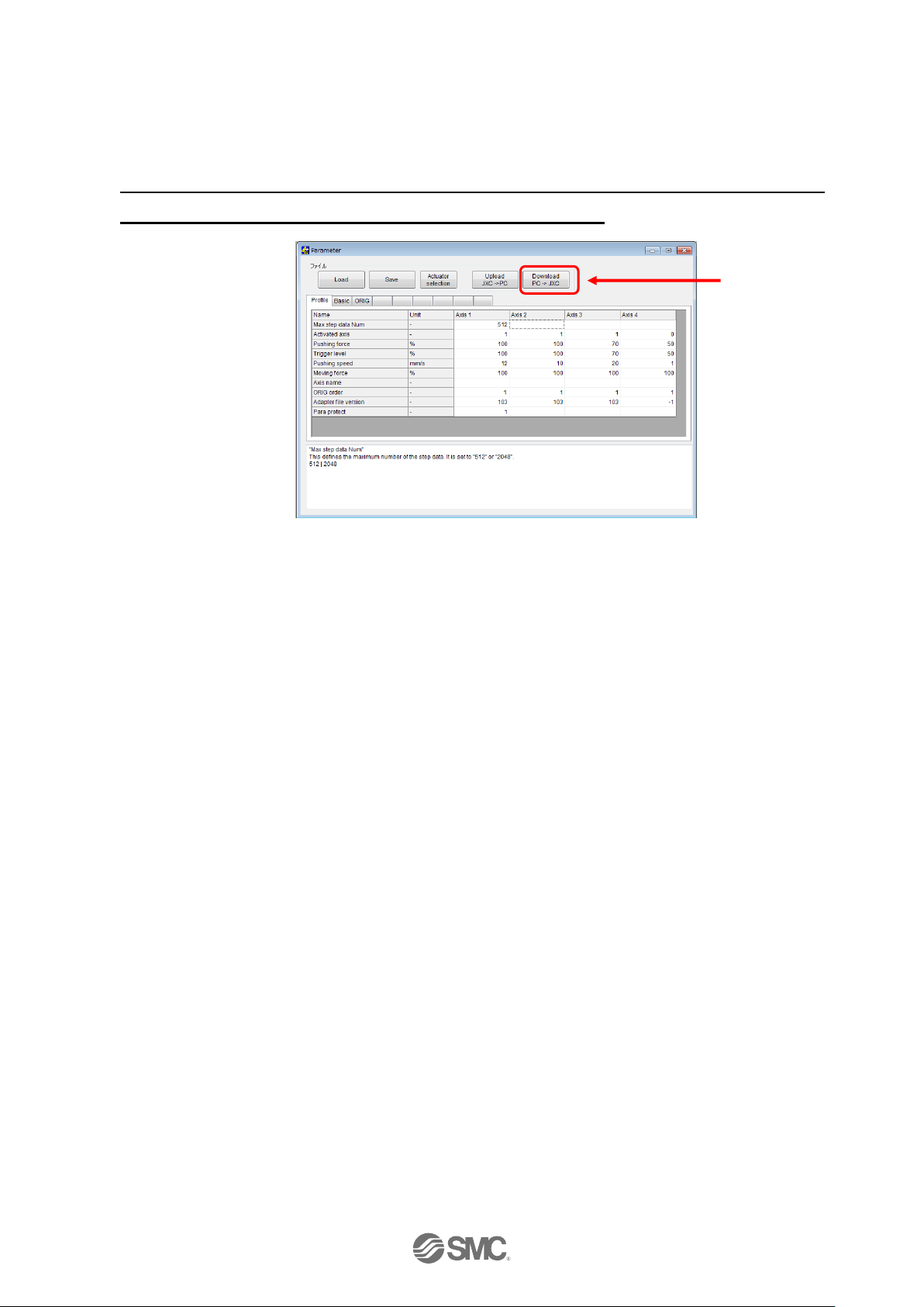
No.SFOD-OMT0010-B
After setting parameters, select the "Download" button in the parameter window. Parameters in the
parameter window will be written to the controller. Writing is completed when the progress bar
disappears and then the setting software is ready to operate.
It is necessary to turn off the power to the controller and turn it on again. The downloaded
parameters will become valid after turning the power on again.
Download
Page 20
- 19 -
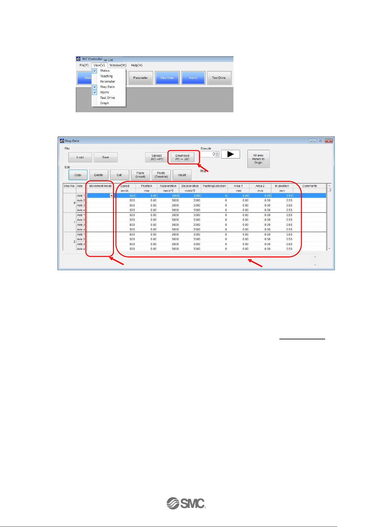
No.SFOD-OMT0010-B
(3) Step data settings
Select "View(V)" at the top of the main window, and select "Step Data".
The Step data window will be displayed.
Select the “▼” button for the movement mode for the axis of the step number to be set. Select the
movement mode shown in the list. Enter the necessary numerical data according to the selected
movement mode.
The setting is different depending on the movement mode. Refer to section
7.4 Step Data
for
details.
After setting the step data, select the "Download" button in the step data window. The step data will
be written to the controller. Writing is completed when the progress bar disappearsand then the
setting software is ready to operate.
Movement mode
Area to input numerical data.
Download
Page 21
- 20 -
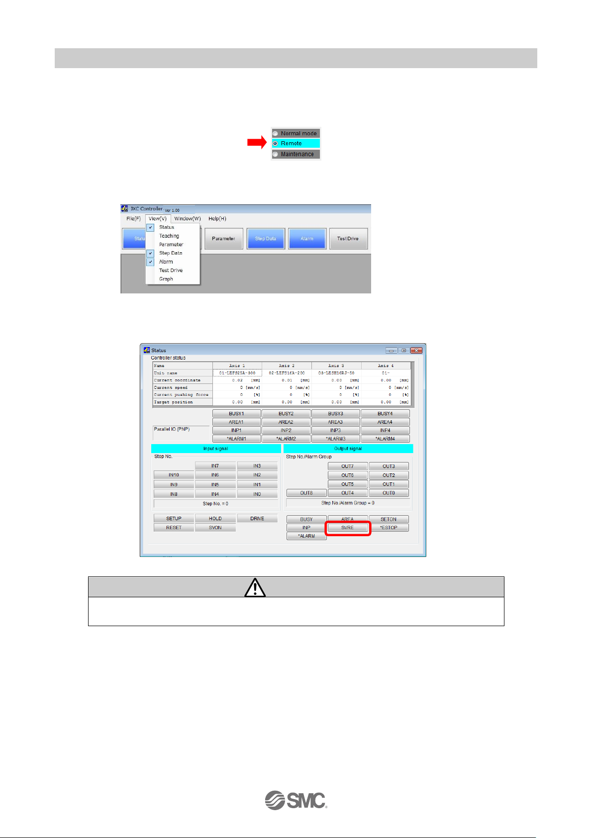
No.SFOD-OMT0010-B
3.7 Check using JOG operation
(1) Change to Remote mode
Change the mode to Remote mode at the top of the main window. The Servo will be turned on by
selecting Remote mode.
Confirm that the Servo is ON. (Confirm SVRE ON in the status window.)
Select "View(V)" at the top of the main window, and select "Status".
The Status window will be displayed. When the Servo is ON, the SVRE box will turn blue in the
Output signal area.
Caution
When the power is supplied, it may take up to 20 seconds from servo ON input to SVRE
ON output, depending on the actuator position or the conditions.
Page 22
- 21 -
No.SFOD-OMT0010-B
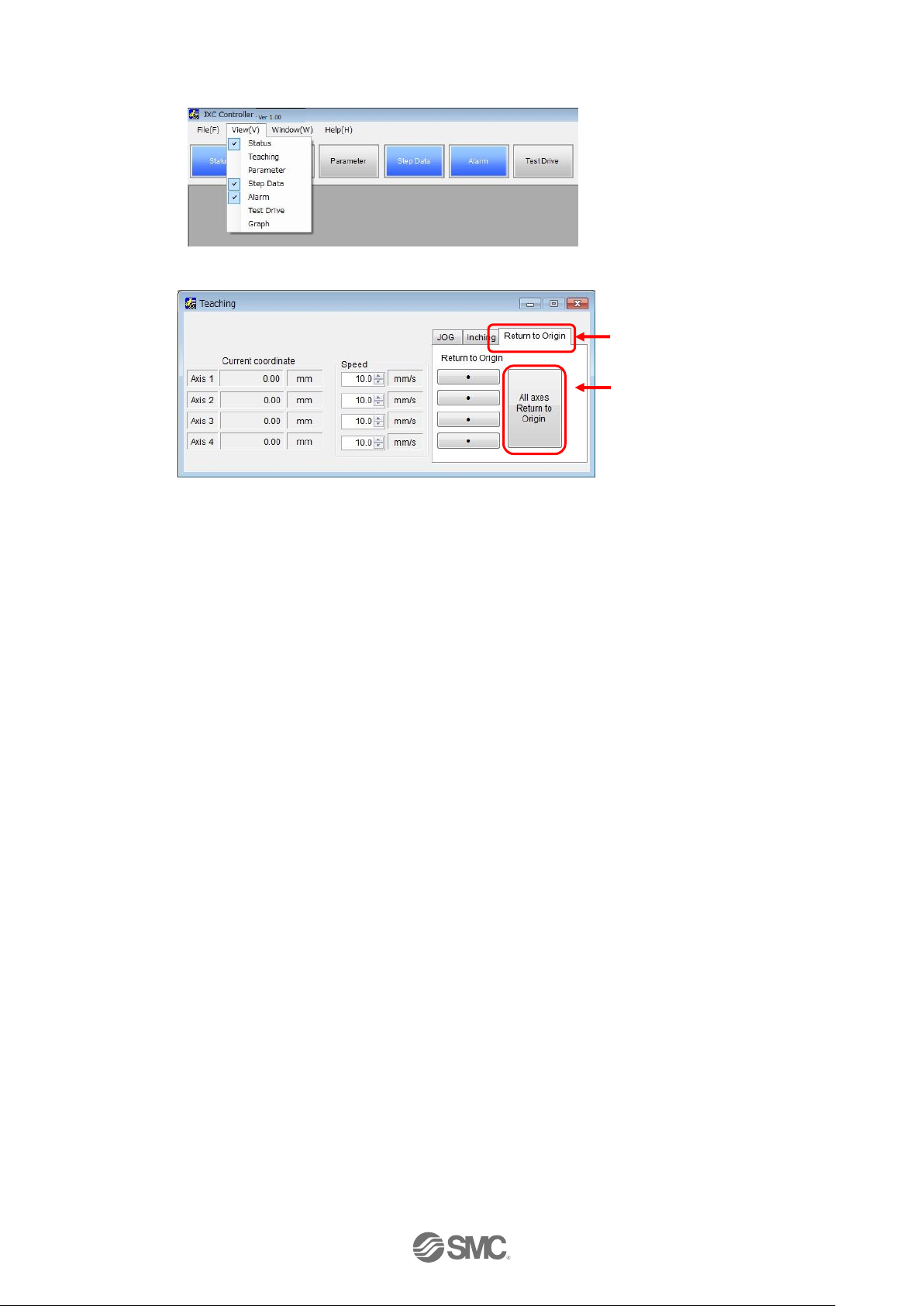
(2) Return to origin
Select "View(V)" at the top of the main window, and select "Teaching".
The teaching window will be displayed.
Select the “Return to Origin” tab. Select “Return to Origin(●)” or “All axes Return to Origin”.
When the return to origin setting is completed, SETON is ON. Confirm that the output signal
SETON turns blue in the status window.
All axes Return to Origin
Return to Origin tab
Page 23
- 22 -
No.SFOD-OMT0010-B
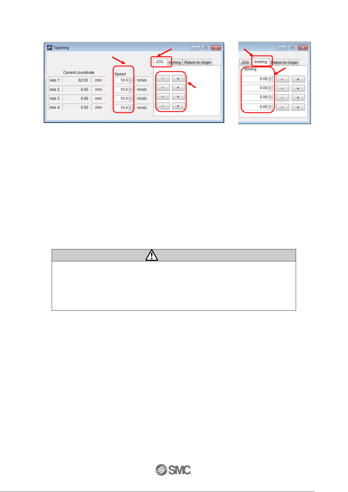
(3) JOG or Inching
Select the “JOG” or “Inching” tab.
(a) JOG
Set the "Speed". The Position will move in the "+" or "-" direction as long as the "+" or "-"
button is pressed.
(b) Inching
Set "Speed" for travel speed and "Moving" for travel distance. The Position will move in the "+"
or "-" direction during setting.
Confirm that the connected actuator travels at the speed or distance according to the connected
actuator setting.
Caution
When perform return to origin operation, JOG function and Inching function for the first
time, make sure that the parameter setting is correct.
When the electronic gear is set, make sure that the actuator travels for the set travel
distance by performing the inching function.
It is possible that unexpected operation will result in accidents, injury, or damage to the
system or actuator.
Speed
JOG tab
+/- button
Inching tab
Travel distance
Page 24
- 23 -
No.SFOD-OMT0010-B
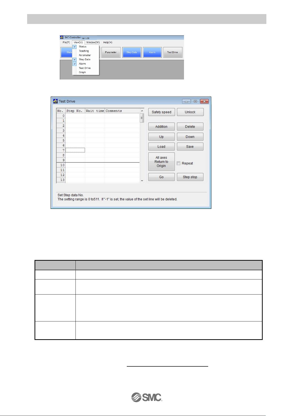
3.8 Operation test using Test Drive
Select "View(V)" at the top of the main window, and select "Test Drive".
The Test Drive window will be displayed.
It is possible to test the set step data in a specified order.
(1) Test Drive setting
Set the order of the step data number for testing in the test drive list window. The table below
shows details of the items required.
Items
Details
No.
Line number.
Step No.
Step number to be executed.
The set line is deleted by entering "-1".
Wait time
Wait time after the actuator has been operated by the step data, specified by
the step number. Unit is msec.
Setting range is 0 to 32767 msec.
Comments
Comments are possible to be entered. (Note that half-width comma "," cannot
be used).
(2) Change to Remote mode
Turn on the Servo, referring to section
3.7 (1) Change to Remote mode.
Page 25
- 24 -
No.SFOD-OMT0010-B
(3) Return to origin
Confirm that SVRE output is ON, refer to section
3.7 (1) Change to Remote mode
. Then, select
"All axes Return to Origin", and perform the “Return to origin” operation.
(4) Test drive starts
Confirm that SETON output is ON, refer to section
3.7 (2) Return to origin
.
Test drive starts by pressing the "Go" button, based on the test drive list.
Test drive is completed when the correct operation is confirmed. If the operation was not as
expected, then refer to section
3.6 (3) Step data settings
to revise the settings.
Caution
Do not disconnect the USB cable while executing step data.
The actuator will stop.
Page 26

- 25 -
No.SFOD-OMT0010-B
4. Product Specifications
4.1 Basic Specifications
Basic specifications of the product.
Item
Specifications
Number of axes per
controller
Max. 4 axis
Controlled motor
Step motor (servo 24 VDC )
Controlled encoder
Incremental phase A / B (Encoder resolution 800 pulse / rotation)
Power supply
specification
Note1)
Main control power supply
Power supply voltage: 24VDC+/-10%
Max. current consumption: 300mA
Motor drive and motor control power supply
Power supply voltage: 24VDC+/-10%
Max. current consumption: Depends on connected actuator.
Note2)
Parallel input
16 inputs (Optically isolated)
Parallel output
32 outputs (Optically isolated)
Serial
communication
USB2.0 (Full Speed 12Mbps)
Memory
Flash ROM and EEPROM
LED indicator
PWR (green), RUN (green), USB (green), ALM (red)
Lock control
With forced lock-release terminal
Note3)
Cable length
I/O cable: 5 m maximum
Actuator cable: 20 m maximum
Cooling method
Natural air cooling
Operating
temperature range
0 to 40oC (No freezing)
Operating humidity
range
90% RH or less (No condensation)
Storage
temperature range
-10 to 60oC (No freezing)
Storage humidity
range
90% RH or less (No condensation)
Insulation
resistance
Between the external terminals and case
50MΩ (500 VDC)
Weight
1050 g (Direct mounting)
1100 g (DIN rail mounting)
Note 1) Do not use a power supply with "inrush currentprotection" for the motor drive power
and motor control power supply.
Note 2) Power consumption depends on the actuator connected.Refer to the actuator
specifications for further details.
Note 3) Applicable to non-magnetizing lock.
Page 27
- 26 -
No.SFOD-OMT0010-B
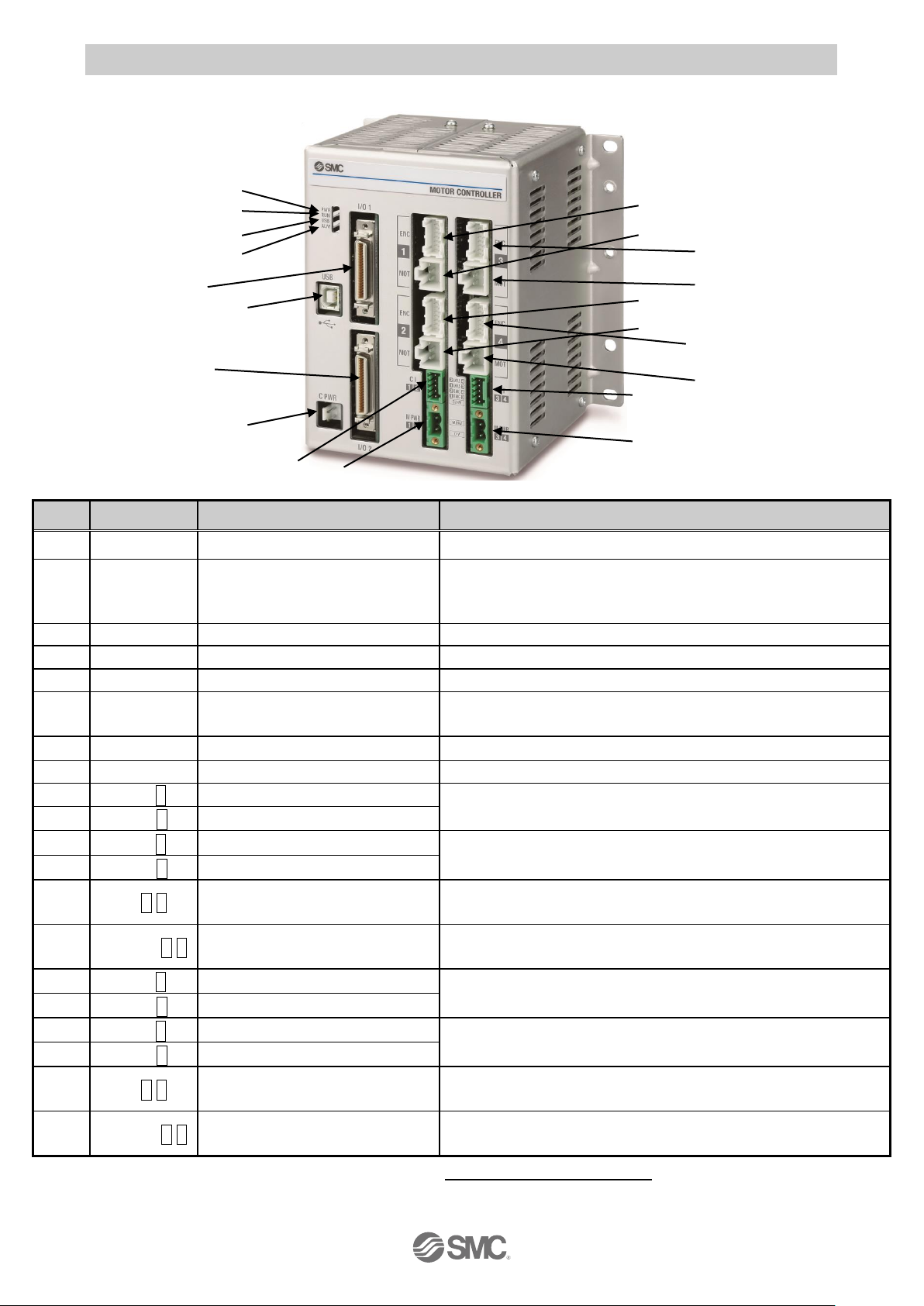
4.2 Parts Description
Detail of the controller parts.
No.
Display
Description
Details
1
PWR
Power supply LED (green)
Power supply ON: LED is ON Power supply OFF: LED is OFF
2
RUN
Operating LED (green)
Operation by parallel I/O: LED is ON
Operation by USB communication: LED is Flashing
Stop: LED is OFF
3
USB
USB LED (green)
USB connected: LED is ON USB not connected: LED is OFF
4
ALM
Alarm LED (red)
Alarm condition: LED is ON No alarm: LED is OFF
5
USB
Serial communication
Connect to a PC using a USB cable.
6
C PWR
Main control power supply
connector (2 pin)
Note)
Main control power supply (+)(-)
7
I/O 1
Parallel I/O connector (40 pins)
Connect to the PLC using an I/O cable.
8
I/O 2
Parallel I/O connector (40 pins)
Connect to the PLC using an I/O cable.
9
ENC1
Encoder connector (16 pins)
Axis 1: Connect the actuator cable.
10
MOT1
Motor power connector (6 pins)
11
ENC2
Encoder connector (16 pins)
Axis 2: Connect the actuator cable.
12
MOT2
Motor power connector (6 pins)
13
CI 1 2
Motor control power supply
connector
Note)
Motor control power supply(+), Axis 1 stop(+), Axis 1 unlock(+), Axis 2
stop(+), Axis 2 unlock (+)
14
M PWR 1 2
Motor drive power connector
Note)
Axis 1, Axis 2 Motor drive power (+), common(-)
15
ENC3
Encoder connector (16 pins)
Axis 3: Connect the actuator cable.
16
MOT3
Motor power connector (6 pins)
17
ENC4
Encoder connector (16 pins)
Axis 4: Connect the actuator cable.
18
MOT4
Motor power connector (6 pins)
19
CI 3 4
Motor control power supply
connector
Note)
Motor control power supply(+), Axis 3 stop(+), Axis 3 unlock(+), Axis
4 stop(+), Axis 4 unlock (+)
20
M PWR 3 4
Motor drive power connector
Note)
Axis 3, Axis 4 Motor drive power (+), common(-)
Note) The connector is included. Refer to section
5. Power supply connector
.
(1)
(2)
(3)
(4)
(5)
(6)
(7)
(8)
(9)
(10)
(11)
(12)
(13)
(14)
(15)
(16)
(20)
(19)
(17)
(18)
Page 28
- 27 -
No.SFOD-OMT0010-B
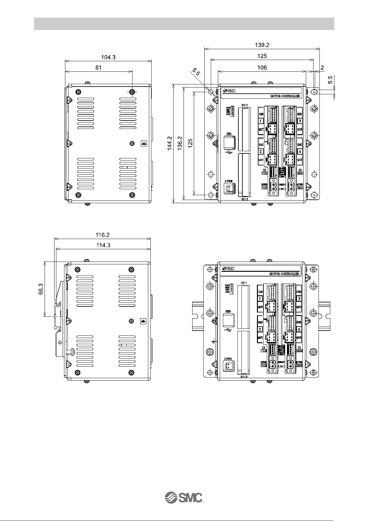
4.3 Dimensions
(1) Direct mounting
(2) DIN rail mounting
Page 29
- 28 -
No.SFOD-OMT0010-B
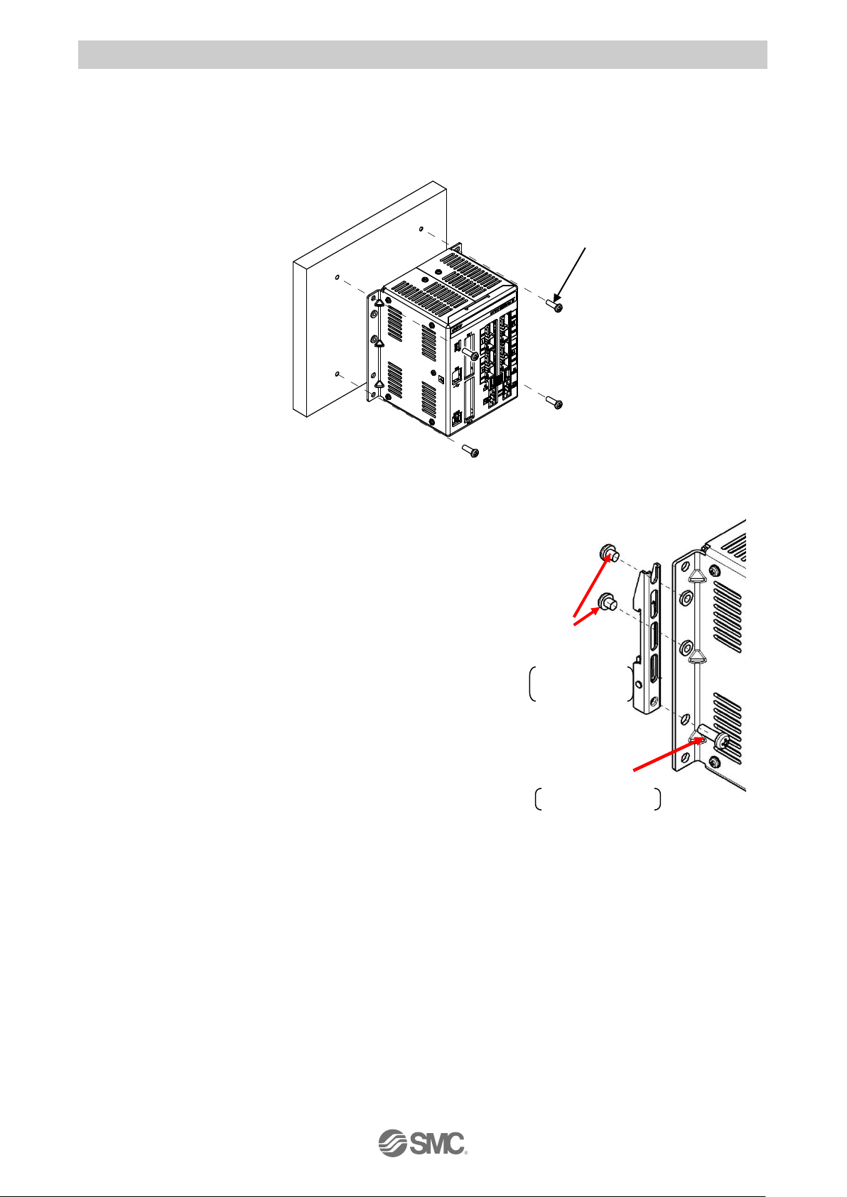
4.4 Mounting
(1) Mounting
There are two ways to mount the controller. (Direct mounting with screws and DIN rail mounting)
Controller mounting methods are shown below.
(a) Direct Mounting with four M5 screws
(b) DIN rail mounting
The figure on the right shows how to mount the DIN rail
mounting brackets.
Secure the DIN rail mounting bracket using the mounting
screws (M5 x 8) 2 places on one side (4 places on both
sides). (Appropriate tightening torque: 3.0Nm)
Secure the DIN rail mounting bracket using the holding
screws (M5 x 14). 1 place on one side (2 places on both
sides). Tighten for approximately 2 threads.
Do not tighten completely.
Mounting screw
M5X8
Included with DIN
rail mounting
bracket
Tightening torque:
3.0 (Nm)
Holdingscrews
M5X14
Included withDIN
rail mounting bracket
Tightening torque: 0.4 to 0.6[Nm]
Mounting screw (M5) 4pcs.
(prepared by customer)
Page 30
- 29 -
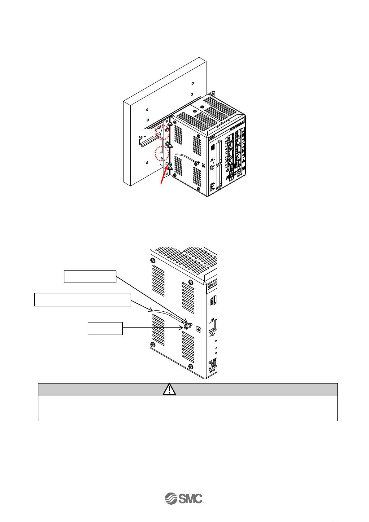
No.SFOD-OMT0010-B
The figure below shows how to mount the controller to the DIN rail. Hook part A on to the DIN
rail. Press part B on to the DIN rail and tighten the holding screws (M5 x 14). (Appropriate
tightening torque: 0.4 to 0.6Nm)
(2) Grounding
Fit the grounding cable with crimped terminal between the M3 screw and shakeproof washer as
shown below and tighten the screw.
Caution
The cable with crimped terminal and shakeproof washer must be prepared by the user.
The controller must be connected to Ground to reduce noise.
Part A
Part B
Holding screw
M5X14
M3 screw
Grounding cable (with crimped terminal)
Shakeproof washer
Page 31

- 30 -
No.SFOD-OMT0010-B
Caution
(1) A dedicated ground connection must be used. Grounding should be to a D-class ground (ground
resistance of 100Ω or less).
(2) The cross sectional area of the grounding cable should be 2mm2 minimum.
The grounding point should be as near as possible to the controller, to keep the grounding cable
as short as possible.
(3) Mounting location
Design the size of the control panel and the installation so that the temperature surrounding the
controller is 40oC or less. Mount the controller vertically with 50 mm or more space at the top and
bottom of the controller as shown below.
Establish the space more than 100mm between the front of the controller and a door (lid) so that
the connectors are possible to connect and disconnect. Leave enough space between the
controllers so that the operating temperature of the controllers remains within the specification
range. Allow sufficient space for mounting. Avoid mounting the controller near a vibration source,
such as a large electromagnetic contactor or no-fuse breaker on the same panel.
Caution
If the mounting surface for the controller is not flat or is uneven, excessive stress could be
applied to the case, which could cause failure. Mount on a flat surface.
Shared grounding: Not acceptable
Controller
Other
equipment
Dedicated grounding: Good
Controller
Other
equipment
D-class ground
(ground with the
resistance less than
100 ohm)
100 or more
Page 32

- 31 -
No.SFOD-OMT0010-B
5. Power supply connector
5.1 Connector specifications
The power supply connector type included is shown below.
(1) Main control power supply connector: C PWR
Use the power cable for main control, JXC-C1.
Specifications of the cable are as follows.
Item
Specifications
Electric wire size
Stranded wire → AWG20 (0.5mm2)
O.D. of sheath →1.76
Wire sheath colour
+24V:Brown
24-0V: Blue
(2) Motor drive power connector: M PWR
Manufactured by Phoenix Contact (Part number MSTB2,5/2-STF-5,08)
Prepare the electrical wiring according to the following specifications (to be prepared by the user).
Item
Specifications
Applicable wire size
Single, Stranded wire → AWG16(1.25mm2)
The rated temperature of the insulation coating should be
60oC or more.
Stripped wire length
When the wire is inserted into the motir drive power connector, insert only the stripped part of the
wire.
Terminal
Function
Description
+24V
Main control power supply (+)
Power supply (+) for main control.
24-0V
Main control power supply (-)
Power supply (-) for main control.
Terminal
Function
Description
0V
Motor power (-)
Power supply (-) common for M24V terminal, C24V
terminal, EMG terminal and LKRLS terminal
M24V
Motor power (+)
Motor drive power supply (+) for Axis 1 and 2 or
Axix 3 and 4.
+24V
24-0V
0V
M24V
Brown
Blue
7mm
3.4
or less
Page 33

- 32 -
No.SFOD-OMT0010-B
(3) Motor control power supply connector: CI
Manufactured by Phoenix Contact (Part number FK-MC0,5/5-ST-2,5)
Prepare the electrical wiring according to the following specifications (to be prepared by the user).
Item
Specifications
Applicable wire size
Single, Stranded wire → AWG20 (0.5mm2)
The rated temperature of the insulation coating should be
60oC or more.
Stripped wire length
When the wire is inserted into the motor control power supply connector, insert only the stripped
Terminal
Function
Functional explanation
C24V
Motor control power
supply (+)
Power supply side (+) for motor control.
EMG1/EMG3
Stop(+)
Release the stop status (+) of Axis 1 or Axis 3.
(Normal operation by applying 24V.)
EMG2/EMG4
Stop(+)
Release the stop status (+) of Axis 2 or Axis 4.
(Normal operation by applying 24V.)
LKRLS1/LKRLS3
Unlock(+)
Release the lock status (+) of Axis 1 or Axis 3.
LKRLS2/LKRLS4
Unlock(+)
Release the lock status (+) of Axis 2 or Axis 4.
Caution
Do not connect multiple wires into one terminal.
Contact failure or short circuit to adjacent wire may lead to malfunction or fire.
EMG1/EMG3 C24V LKRLS2/LKRLS4 EMG2/EMG4 LKRLS1/LKRLS3
8mm
2.0
or less
Page 34

- 33 -
No.SFOD-OMT0010-B
5.2 Wiring
Connect the main control power supply, motor drive and motor control power supply while referring to
(1) to (3) below, and then insert into the controller C PWR, Cl and M PWR.
(1) Wiring of the power supply connector
Connect the main control power supply 24V and 0V to the main control power supply connector
+24V and 24-0V terminals.
Connect the motor drive and motor control power supply 24V and 0V to the motor drive power
connector M24V and 0V terminals.
Connect the motor drive and motor control power supply 24V to the motor control power supply
connector C24V terminal.
Caution
(1)Do not use a power supply with “inrush current protection” for the motor drive and motor control
power supply. The power supply capacity should be greater than the "Momentary maximum
power consumption” of the actuator specifications.
(2)Connector ‘CI3 4’ must be connected even when Axis 3 and 4 are not used.
If not, a "Modbus Error" alarm will be generated.
(3)The motor power and motor control power supply should be powered at the same time or prior to
the main control power supply.
If the sequence of these power supplies is different then a "ModbusErr or" alarm will be generated.
24V
Motor drive and
motor control
power supply
0V
M24V
0V
Open/close lever
Press the open/ close lever with a flat blade
screwdriver and insert the wire into the wire entry.
- Dedicated flat blade screwdriver (recommended)
Phoenix Contact (Part No: SZS0.4×2.0)
Wire entry
24V
0V
Motor drive and
motor control
power supply
C 24V
EMG1/EMG3
LKRLS1/LKRLS3
Motor control power supply connector
EMG2/EMG4
LKRLS2/LKRLS4
M3 screw
Screw type terminal.
Loosen the screws using a flat blade screwdriver.
Insert the wires in the wire inlet.
Tightening torque: 0.5 to 0.6Nm
+24V
24-0V
24V
Main control
power
supply
0V
Page 35

- 34 -
No.SFOD-OMT0010-B
Motor drive and
motor control
power supply
Motor drive and
motor control
power supply
CI1 2
CI3 4
CI3 4
CI1 2
(2) Wiring of the stop switch
A Stop switch must be installed by the user to stop the actuator in abnormal situations. The
actuator stops its operation when the external shutdown switch is activated.
- Stop (Stop switch)
To stop the controller, connect the stop switch (B contact) between the motor drive and motor
control power supply and the EMG terminal of the motor control power supply connector.
- Stop (Stop relay contact)
If there is a separate shutdown circuit for the whole installation or there are multiple controllers
with different power supplies, connect a relay (B contact) between the motor drive and motor
control power supply and the EMG terminal of the motor control power supply connector.
(Circuit example: The Figure below shows the stop status).
Caution
When the EMGx input is turned off (0V) during operation, the corresponding actuator will stop with
maximum deceleration and the servo will be turned off thereafter.
24V
0V
24 VDC
Ry
0V
Emergency
stop
Surge suppressor
The stop is
released
Switch
Ry
U
C 24V
EMG1
LKRLS1
EMG2
LKRLS2
Motor control power supply connector
C 24V
EMG3
LKRLS3
EMG4
LKRLS4
Motor control power supply connector
Stop switch
24V
0V
C 24V
EMG1
LKRLS1
Motor control power supply connector
EMG2
LKRLS2
C 24V
EMG3
LKRLS3
Motor control power supply connector
EMG4
LKRLS4
Page 36

- 35 -
No.SFOD-OMT0010-B
C I□3□
4
Motor drive and
motor control
power supply
CI3 4
CI1 2
Motor power shutdown (relay contact)
If it is necessary to have a circuit to shutdown the motor drive power externally, relay contacts
should be placed between the motor drive and motor control power supply and the M24V of
the motor control power supply connector and the EMG terminal of the motor control power
supply connector. (Circuit example: The Figure below shows the stop status)
Warning
(1) If it is necessary to have a circuit to shutdown the motor power supply, relay contacts should be
placed between the motor drive and motor control power supply and the M24V terminal of the
motor drive power connector and the EMG terminal of the motor control power supply
connector. The actuator may make unexpected movement.
(2) Do not perform a return to origin operation (SETUP input ON) when the motor drive power
(M24V) is disconnected.
The controller cannot recognize the correct origin point if a return to origin instruction is made
with the motor drive power (M24V) disconnected.
(3) When wiring the stop switch, connect the switch such that EMG1 to EMG4 are shut down
together.
24V
0V
C 24V
EMG1
LKRLS1
Motor control power supply connector
EMG2
LKRLS2
C 24V
EMG3
LKRLS3
Motor control power supply connector
EMG4
LKRLS4
Ry
Motor drive power connector
Motor drive power connector
M PWR 1 2
M PWR 3 4
0V
M 24V
0V
M 24V
24 VDC
Ry
0V
Stop
Switch
Surge suppressor
The stop is
released
Switch
Ry
U
Page 37

- 36 -
No.SFOD-OMT0010-B
6. Details of parallel I/O connector
This controller is available with NPN type (JXC73) or PNP type (JXC83) parallel I/O.
6.1 Parallel I/O specifications
■Input specifications
■Output specifications
(NPN) (NPN)
(PNP) (PNP)
6.2 Parallel I/O circuit (NPN, PNP)
(1)Parallel I/O input circuit
No.
Item
Specifications
1
Output circuit
Internal circuit and
Optically isolated
2
Number of outputs
32
3
Max. voltage between
terminals
30 VDC
4
Max. output current
100mA
5
Saturation voltage
-COM+1.8V (Max.)
No.
Item
Specifications
1
Input circuit
Internal circuit and Optically
isolated
2
Number of inputs
16 3 Voltage
24VDC+/-10%
4
Input current at
ON state
5.1mA+/-20% (at 24 VDC)
No.
Item
Specifications
1
Output circuit
Internal circuit and
Optically isolated
2
Number of outputs
32
3
Max. voltage between
terminals
30 VDC
4
Max. output current
100mA
5
Saturation voltage
+COM-1.8V (Max.)
No.
Item
Specifications
1
Input circuit
Internal circuit and Optically
isolated
2
Number of inputs
16 3 Voltage
24VDC+/-10%
4
Input current at
ON state
5.1mA+/-20% (at 24 VDC)
NPN type
(a)
+COM1, +COM2
(b)
IN0 to IN10, SETUP, HOLD,
DRIVE, RESET, SVON
Inside the controller
(a)
(b)
External
I/O 1
I/O 2
Unused
PNP type
(a)
-COM1, -COM2
(b)
IN0 to IN10, SETUP, HOLD,
DRIVE, RESET, SVON
Inside the controller
External
I/O 1
I/O 2
Unused
(a)
(b)
4.7 kΩ
2.2 kΩ
4.7 kΩ
2.2 kΩ
Page 38

- 37 -
No.SFOD-OMT0010-B
(2)Parallel I/O output circuit
-NPN type
-PNP type
I/O 1
I/O 2
(a)
+COM3, +COM4
(b)
BUSY1 to BUSY4, AREA1 to
AREA4, INP1 to INP4, ALARM1
to ALARM4
(c)
-COM3, -COM4
(a)
+COM1, +COM2
(b)
OUT0 to OUT8, BUSY, AREA,
SETON, INP, SVRE, ESTOP,
ALARM
(c)
-COM1, -COM2
I/O 1
(a)
+COM1, +COM2
(b)
OUT0 to OUT8, BUSY, AREA,
SETON, INP, SVRE, ESTOP,
ALARM
(c)
-COM1, -COM2
I/O 2
(a)
+COM3, +COM4
(b)
BUSY1 to BUSY4, AREA1 to
AREA4, INP1 to INP4,
ALARM1 to ALARM4
(c)
-COM3, -COM4
External
Inside the controller
10KΩ
20KΩ
(a)
(b)
(c)
External
Inside the controller
10KΩ
4.7KΩ
(a)
(b)
(c)
Page 39

- 38 -
No.SFOD-OMT0010-B
6.3 Parallel I/O signals
Pin No.
Insulator colour
Dot mark
Dot colour
Pin No.
Insulator colour
Dot mark
Dot colour
1
Orange
■
Black
11
Orange
■■■
Black
21
Orange
■
Red
31
Orange
■■■
Red
2
Grey
■
Black
12
Grey
■■■
Black
22
Grey
■
Red
32
Grey
■■■
Red
3
White
■
Black
13
White
■■■
Black
23
White
■
Red
33
White
■■■
Red
4
Yellow
■
Black
14
Yellow
■■■
Black
24
Yellow
■
Red
34
Yellow
■■■
Red
5
Pink
■
Black
15
Pink
■■■
Black
25
Pink
■
Red
35
Pink
■■■
Red
6
Orange
■■
Black
16
Orange
■■■■
Black
26
Orange
■■
Red
36
Orange
■■■■
Red
7
Grey
■■
Black
17
Grey
■■■■
Black
27
Grey
■■
Red
37
Grey
■■■■
Red
8
White
■■
Black
18
White
■■■■
Black
28
White
■■
Red
38
White
■■■■
Red
9
Yellow
■■
Black
19
Yellow
■■■■
Black
29
Yellow
■■
Red
39
Yellow
■■■■
Red
10
Pink
■■
Black
20
Pink
■■■■
Black
30
Pink
■■
Red
40
Pink
■■■■
Red
Signals are different for I/O1 and I/O2. Refer to the table below for details.
Page 40

- 39 -
No.SFOD-OMT0010-B
(1) I/O1
-Input side
Pin No.
Signal
name
Description
1
+COM1
Connect the 24 VDC power supply to the input/ output signals
For IN0 to IN10, SETUP, HOLD, DRIVE, RESET, SVON
For OUT0 to OUT8, BUSY, AREA, SETON, INP, SVRE, ESTOP, ALARM
21
+COM2
2
IN0
Step data instruction Bit No.(Standard: When 512 is used)
Step data instruction Bit No. (Input is instructed in the combination of IN0 to
IN8.)
Ex. (Assign step data No.3)
IN8
IN7
IN6
IN5
IN4
IN3
IN2
IN1
IN0
OFF
OFF
OFF
OFF
OFF
OFF
OFF
ON
ON 0 0 0 0 0 0 0 1
1
22
IN1 3 IN2
23
IN3 4 IN4
24
IN5 5 IN6
25
IN7 6 IN8
26
IN9
Step data instruction extended mode bit No (Extended: 2048 is used)
7
IN10
27
SETUP
Command to Return to Origin
Actuators return to origin based on the order of setting for return to origin.
When SVRE output is ON, the SETUP operation (return to origin) will be
performed. During the SETUP operation, BUSY will be turned ON and after
completion of the SETUP operation, SETON and INP will be turned ON.
8
HOLD
Pause of operation
All axes in operation are paused.
If HOLD input is ON during operation, the speed decreases at maximum
deceleration of the basic parameter until the actuator stops. The remaining
stroke will be on hold as long as HOLD is ON and when HOLD is turned OFF,
the actuator restarts to travel the remaining stroke.
Caution
(1) Do not command SETUP or DRIVE while the HOLD input is ON.
The actuator may make unexpected movements.
(2) While HOLD input is ON, do not move the actuator position.
Changing the residual travel distance may cause inconsistency with
the target position.
(3) HOLD input is invalid during return to origin operation.
28
DRIVE
Operation instruction
Read the step data from IN0 to IN8 while the DRIVE signal is ON and start
operation.
The number of ongoing steps is output to the OUT terminal when the DRIVE
signal is ON.
Binary code
Page 41

- 40 -
No.SFOD-OMT0010-B
Pin No.
Signal
name
Description
9
RESET
Alarm reset and interruption of operation
When RESET is turned ON during operation, the speed decreases at
maximum deceleration of the basic parameter until the actuator stops.
INP and OUT0 to OUT10 are OFF. (However, if the actuator is stopped
within the in-position range, the INP will be turned ON).
An Alarm is reset when the RESET signal is turned ON if an alarm has
been generated. (Some alarms cannot be reset by the RESET
command).
Caution
(1) Do not command SETUP or DRIVE while the RESET input is ON.
The actuator may make unexpected movements.
(2) If the RESET input is ON during a return to origin operation, return
to origin may not be available when the RESET input is turned OFF.
In this case, turn on the servo, and then turn on the SETUP input.
29
SVON
Servo ON instruction
When SVON is ON, the servo motor for all axes will be turned ON.
Note1)
When SVON is OFF, the servo motor will be turned OFF.
Note 1) When power is supplied, it may take up to 20 seconds from Servo ON to SVRE ON,
depending on the actuator position or conditions.
Page 42

- 41 -
No.SFOD-OMT0010-B
-Output side
Pin No.
Signal
name
Description
10
OUT0
Output the number of ongoing step data.
When the operation is started and the DRIVE input is turned ON, a Bit No. corresponding
to the number of the active step data will be output from these terminals. These output
signals will be updated when the DRIVE input is turned ON.
Caution
(1) When RESET is turned ON, these terminals are turned OFF.
(2) During an alarm, these terminals output the alarm group.
30
OUT1
11
OUT2
31
OUT3
12
OUT4
32
OUT5
13
OUT6
33
OUT7
14
OUT8
34
BUSY
(OUT9)
The Busy signal turns on until the completion of operation time (theoretically value) of all
actuators, and also during the movement of one or more actuators. (OR of BUSY1 to
BUSY4.)However, when the positioning operation of pushing operation is inhibited and the
movement stops, the Busy signal keeps turning ON exceptionally until operation is
released. (Not OR of BUSY1 to BUSY4.)
The Bit No is output during step data in extended mode.
Note
3)
15
AREA
(OUT10)
The Area signal turns on when all actuators are within the area output range. (AND of
AREA1 to AREA4)
The Bit No is output during step data in extended mode.
Note
3)
35
SETON
Return to origin completion signal.
SETON turns on when all axes have completed the return to origin operation.
16
INP
Positioning complete signal
INP turns on according to the conditions below.(AND of INP1 to INP4)
Movement
mode
Details
Positioning
operation
When the actuator moves to within this range from the target position after the
positioning completion time (theoretical value), the INP output will turn ON.
Pushing
operation
When the Pushing force becomes more than the set "Trigger level" value in the
profile parameter and the actuator stopped within the pushing area, the INP output
will turn ON.
36
SVRE
The Servo ON signal turns on when the servo motor is ON.
Note1)
17
ESTOP
ESTOP turns OFF when EMG signal stops
Note2).
37
ALARM
ALARM turns OFF when an alarm is generated to one or more actuator. (Reverse of OR
of ALARM1 to ALARM4)
Note
2)
18
-COM1
Connects the power supply 0V to the input/output signals
For OUT0 to OUT7
19
-COM1
38
-COM1
20
-COM2
Connects the power supply 0V to the input/output signals
For OUT8, BUSY, AREA, SETON, INP, SVRE, ESTOP, and ALARM
39
-COM2
40
-COM2
Note 1) When power is supplied, it may take up to 20 seconds from Servo ON to SVRE ON, depending
on the actuator position or conditions.
Note 2) Negative logic signal.
Note 3) For BUSY and AREA signals, use BUSY1 to BUSY4 and AREA1 to AREA4 for I/O2 (optional).
Page 43

- 42 -
No.SFOD-OMT0010-B
(2) I/O2
-Input side
Pin No.
Signal name
Description
1
+COM3
Connects the power supply 24 V to the input/output signals
For BUSY1 to BUSY4, AREA1 to AREA4, INP1 to INP4, and ALARM1 to
ALARM4.
21
+COM4
2
N.C.
Unused
22 3 23 4 24 5 25 6 26 7 27 8 28 9 29
-Output side
Pin No.
Signal name
Description
10
BUSY1
Busy signal for Axis x
When the actuator starts to operate, the BUSY signal will be turned
ON until the completion of operation time (theoretically value). After
the completion of operation time if the actuator has stopped, the
BUSY signal will be turned off.
30
BUSY2
11
BUSY3
31
BUSY4
12
AREA1
Area signal for Axis 1
32
AREA2
Area signal for Axis 2
13
AREA3
Area signal for Axis 3
33
AREA4
Area signal for Axis 4
14
INP1
Positioning complete signal for Axis 1
34
INP2
Positioning complete signal for Axis 2
15
INP3
Positioning complete signal for Axis 3
35
INP4
Positioning complete signal for Axis 4
16
ALARM1
Alarm signal for Axis 1
Note1)
36
ALARM2
Alarm signal for Axis 2
Note1)
17
ALARM3
Alarm signal for Axis 3
Note1)
37
ALARM4
Alarm signal for Axis 4
Note1)
18
-COM3
Connect the power supply 0V to the input/output signals
For BUSY1 to BUSY4, AREA1 to AREA4.
19
-COM3
38
-COM3
20
-COM4
Connect the power supply 0V to the input/output signals
For INP1 to INP4, ALARM1 to ALARM4.
39
-COM4
40
-COM4
Note 1) Negative logic signal.
Page 44

- 43 -
No.SFOD-OMT0010-B
The table below shows the changes in the output signal with respect to the state of the controller.
BUSY
INP
SVRE
Lock
SETON
OUT0 to 8
Controller powered down [SVOFF] with no
motion
OFF
OFF
OFF
Lock
OFF
OFF
Controller powered down [SVON] with no
motion
OFF
OFF
Note1)
ON
Unlock
OFF
OFF
During Return to origin
ON
OFF
ON
Unlock
OFF
OFF
The actuator is at the origin, on completion of
[SETUP]
OFF
ON
Note1)
ON
Unlock
ON
OFF
During movement by positioning/pushing
operation
ON
OFF
ON
Unlock
ON
ON
Note2)
The actuator is paused by [HOLD]
OFF
OFF
Note4)
ON
Unlock
ON
ON
Note2)
On completion of the positioning operation.
OFF
ON
ON
Unlock
ON
ON
Note2)
Stopped due to pushing a workload in
pushing operation.
OFF
ON
ON
Unlock
ON
ON
Note2)
Stopped due to no detection of a workload in
pushing operation.
OFF
OFF
ON
Unlock
ON
ON
Note2)
Servo is OFF after return to origin.
OFF
OFF
OFF
Lock
ON
ON
Note3)
EMG signal stop from the CI connector after
the actuator is at the origin.
OFF
OFF
OFF
Lock
ON
ON
Note3)
Note1) The output turns on when the actuator is within the range defined in the basic parameter setup.
Note 2) The output is updated due to the transition of (OFF→ON) of the DRIVE input signal.
Note 3) Retain the previous state.
Note 4) The output turns on when the actuator is "In position" according to the step data.
Output
Status
Page 45

- 44 -
No.SFOD-OMT0010-B
6.4 Parallel I/O Wiring Example
The Wiring depends on the parallel input/output type of the controller (NPN or PNP).
(1) NPN type
Caution
Prepare a separate power supply for the main control, motor drive and motor control and input/ output
signal.
I/O 1
OUT0
10
OUT1
30
OUT2
11
OUT3
31
OUT4
12
OUT5
32
OUT6
13
OUT7
33
OUT8
14
BUSY
(OUT9)
34
AREA
(OUT10)
15
SETON
35
INP
16
SVRE
36
ESTOP
17
ALARM
37
-COM1
18
-COM1
19
-COM1
38
-COM2
20
-COM2
39
-COM2
40
+COM1
1
+COM2
21
IN0
2
IN1
22
IN2
3
IN3
23
IN4
4
IN5
24
IN6
5
IN7
25
IN8
6
IN9
26
IN10
7
SETUP
27
HOLD
8
DRIVE
28
RESET
9
SVON
29
24 VDC
Load
Load
Load
Load
Load
Load
Load
Load
Load
Load
Load
Load
Load
Load
Load
Load
Page 46

- 45 -
No.SFOD-OMT0010-B
Caution
+COM1, +COM2 and +COM3, +COM4 are not connected inside the controller. When I/O2 is used,
connect +COM1, +COM2 and +COM3, +COM4 to the 24V side of the common input/ output signal 24
VDC power supply.
Caution
-COM1, -COM2, -COM3, -COM4 are not connected inside the controller. Connect the corresponding
common -COM of the 0V side of the input/ output signal 24 VDC power supply.
I/O 2
BUSY1
10
BUSY2
30
BUSY3
11
BUSY4
31
AREA1
12
AREA2
32
AREA3
13
AREA4
33
INP1
14
INP2
34
INP3
15
INP4
35
ALARM1
16
ALARM2
36
ALARM3
17
ALARM4
37
-COM3
18
-COM3
19
-COM3
38
-COM4
20
-COM4
39
-COM4
40
+COM3
1
+COM4
21
N.C.
Note 1)
2
N.C.
Note 1)
22
N.C.
Note 1)
3
N.C.
Note 1)
23
N.C.
Note 1)
4
N.C.
Note 1)
24
N.C.
Note 1)
5
N.C.
Note 1)
25
N.C.
Note 1)
6
N.C.
Note 1)
26
N.C.
Note 1)
7
N.C.
Note 1)
27
N.C.
Note 1)
8
N.C.
Note 1)
28
N.C.
Note 1)
9
N.C.
Note 1)
29
Note 1) Not connected
24 VDC
Load
Load
Load
Load
Load
Load
Load
Load
Load
Load
Load
Load
Load
Load
Load
Load
Page 47

- 46 -
No.SFOD-OMT0010-B
(2) PNP type
I/O 1
OUT0
10
OUT1
30
OUT2
11
OUT3
31
OUT4
12
OUT5
32
OUT6
13
OUT7
33
OUT8
14
BUSY
(OUT9)
34
AREA
(OUT10)
15
SETON
35
INP
16
SVRE
36
ESTOP
17
ALARM
37
-COM1
18
-COM1
19
-COM1
38
-COM2
20
-COM2
39
-COM2
40
+COM1
1
+COM2
21
IN0
2
IN1
22
IN2
3
IN3
23
IN4
4
IN5
24
IN6
5
IN7
25
IN8
6
IN9
26
IN10
7
SETUP
27
HOLD
8
DRIVE
28
RESET
9
SVON
29
24 VDC
Load
Load
Load
Load
Load
Load
Load
Load
Load
Load
Load
Load
Load
Load
Load
Load
Page 48

- 47 -
No.SFOD-OMT0010-B
Caution
+COM1, +COM2 and +COM3, +COM4 are not connected inside the controller. When I/O2 is used,
connect +COM1, +COM2 and +COM3, +COM4 to the 24V side of the common input/ output signal 24
VDC power supply.
Caution
-COM1, -COM2, -COM3, -COM4 are not connected inside the controller. Connect the corresponding
common -COM of the 0V side of the input/ output signal 24 VDC power supply.
I/O 2
BUSY1
10
BUSY2
30
BUSY3
11
BUSY4
31
AREA1
12
AREA2
32
AREA3
13
AREA4
33
INP1
14
INP2
34
INP3
15
INP4
35
ALARM1
16
ALARM2
36
ALARM3
17
ALARM4
37
-COM3
18
-COM3
19
-COM3
38
-COM4
20
-COM4
39
-COM4
40
+COM3
1
+COM4
21
N.C.
Note 1)
2
N.C.
Note 1)
22
N.C.
Note 1)
3
N.C.
Note 1)
23
N.C.
Note 1)
4
N.C.
Note 1)
24
N.C.
Note 1)
5
N.C.
Note 1)
25
N.C.
Note 1)
6
N.C.
Note 1)
26
N.C.
Note 1)
7
N.C.
Note 1)
27
N.C.
Note 1)
8
N.C.
Note 1)
28
N.C.
Note 1)
9
N.C.
Note 1)
29
Note 1) Not connected
24 VDC
Load
Load
Load
Load
Load
Load
Load
Load
Load
Load
Load
Load
Load
Load
Load
Load
Page 49

- 48 -
No.SFOD-OMT0010-B
7. Setting Data Entry
In order to move the actuator to a specific position, it is necessary to program the parameters and
step data in the controller using a PC with the controller setting software installed. The data entered
using the controller setting software will be stored in the memory of the controller.
7.1 Profile parameter
The “Profile parameter” is the setting data for the controller specifications.
Note: “XX” = Become effective just after storing in the controller
“X” = Become effective after restarting the controller
“-“ = The parameter cannot be changed (fixed value)
Description
Input range
Explanation
Write
Max step data
Num
512 or 2048
Set the maximum step data number
X
Activated axis
0 or 1
Validity of axes to be set in the controller. "Disabled" axis is ignored
regardless of the connection with the actuator.
0: Disabled
1: Enabled
X
Pushing force
Note1)
The force for the pushing operation. Pushing is performed with this
pushing force when the pushing operation is selected by the step data.
(Setting per step data is not possible.)
X
Trigger level
Note1)
A condition where the INP output signal is ON during the pushing
operation. When the actuator generates a force above the trigger level
value during the pushing operation, INP will be turned ON. (Setting per
step data is not possible.)
X
Pushing speed
Note1)
The movement speed for the pushing operation. (Setting per step data
is not possible.)
X
Moving force
Note1)
The setting to define the maximum force during the positioning
operation. (Setting per step data is not possible.)
X
Axis name
Note1)
Define the axis name of the actuator.
X
ORIG order
1 to 4
The order from 1 to 4 is assigned to axes for the return to origin
operation when all axes are to return to origin. The axes return to origin
from 1 according to the order assigned.
Multiple axes are possible to return to origin simultaneously by setting
the same order number.
[Setting example]
(1) Axis 1: 1, Axis 2: 2, Axis 3: 2, Axis 4:3
The order of returning starts from Axis 1, then Axis 2 and 3, and
then Axis 4.
(2) Axis 1: 1, Axis 2: 1, Axis 3: 1, Axis 4:1
Four axes return simultaneously.
Caution
Simultaneous return to origin of 4 axes is not synchronous.
X
Adapter file
version
Fixed value
This is a fixed value for this controller. Do not change the setting.
-
Para protect
1 or 2
Set the range in which parameter and step data are possible to be
changed.
1: Basic parameter + Return to origin parameter + Step data
2: Basic parameter + Return to origin parameter
X
Note1) The range varies depending on the actuator. Refer to the actuator operation manual for more
details.
Page 50

- 49 -
No.SFOD-OMT0010-B
7.2 Basic parameter
The “Basic parameter” is the data to define the operating conditions of the controller, conditions of the
actuator, etc.
Activation: “XX” = Become effective just after storing in the controller
“X” = Become effective after restarting the controller
“-“ = The parameter cannot be changed (fixed value).
Description
Input range
Explanation
Write
Controller ID
Fixed value
This is a fixed value for this controller. Do not change the setting.
-
Stroke(+)
Note1)
Define the positive (+) limit of the position. [Unit: mm]
Any value greater than the [stroke(+)] value cannot be entered in the
“Position” field data of the step data setup.
XX
Stroke(-)
Note1)
Define the negative (-) limit of the position. [Unit: mm]
Any value less than the [stroke(-)] value cannot be entered in the
“Position” field data of the step data setup.
XX
Max speed
Note1)
Define the maximum limit of speed. [Unit: mm/s]
Any value greater than the [Max speed] value cannot be entered in the
“Speed” field data of the step data setup.
-
Max ACC/DEC
Note1)
Define the maximum limit of acceleration or deceleration. (Unit:mm/s2)
Any value greater than the [Max ACC/DEC] value cannot be entered in
the step data.This setting also defines the deceleration when the
actuator is stopped by the "HOLD" and "RESET" input signals.
-
Def In position
Note1)
Set the INP output range to Origin Position after a Return to Origin.
[Unit: mm]
XX
ORIG offset
Note1)
Define the position of the actuator after the Return to origin operation.
[Unit: mm]
Caution
If the value for the “ORIG offset” is changed, the “Stroke (+)” and
“Stroke (-)” in the basic parameters should be checked.
XX
Max force
Note1)
Set the maximum possible force for "Pushing Force" in the profile
parameters.
XX
Option 1
Fixed value
This is a fixed value for this controller. Do not change the setting.
-
Note1) The range varies depending on the actuator. Refer to the actuator operation manual for more details.
■ The ORIG offset is 0 (mm)
■The ORIG offset is 100 (mm).
In the examples on the left, the
actuator positions are not
different but the reference point
that the controller recognizes will
be changed after the Return to
origin operation.
Controller recognizes position after
return to home position (0mm)
Controller recognizes
Position after return to home
position (100mm)
M
M
Actuator
Actuator
Page 51

- 50 -
No.SFOD-OMT0010-B
Description
Input range
Explanation
Write
Undefined No.11
1 to 4096
Define the electronic Gear.
- Undefined No.11: "Electronic Gear (numerator)"
- Undefined No.12: "Electronic Gear (denominator)"
This product controls the LE series motor (800 pulse per rotation).
Please refer to Supplement 1. Actuator Specifications for the travel
distance of the motor per rotation.
[Setting example]
(1) "Electronic Gear (numerator): 1", "Electronic Gear (denominator): 1"
→ The motor makes one turn when 800 pulses are input.
(2) "Electronic Gear (numerator): 1", "Electronic Gear (denominator): 2"
→ The motor makes one turn when 1600 pulses are input.
(3) "Electronic Gear (numerator): 2", "Electronic Gear (denominator): 1"
→ The motor makes one turn when 400 pulses are input.
"Electronic Gear (numerator): 1", "Electronic Gear (denominator): 1" is
recommended. If other values are entered, vibration or noise of the
actuator could result.
When "0" is set, it is recognized as "1".When a value greater than "4097"
is set, it is recognized as "4096".
Caution
When interpolation is performed for the actuators of different
leads, the travel distance per pulse must be the same.
Set the electronic Gear for Axis 2, 3 or 4 so that the travel
distance are the same as Axis 1.
[Setting example]
Axis
Actuator
Lead
Electronic gear ratio
Axis 1
LEY16C-300
2.5mm
1/ 1
Axis 2
LEY16B-300
5mm
25/ 50
Axis 3
LEY16A-300
10mm
25/ 100
Set Axis 2 and 3 so that their travel distance becomes 2.5mm per
800 pulse.
Electronic Gear ratio
= Lead of Axis 1/ Lead of Axis 2(or Axis 3)
=2.5mm/5mm (or 2.5mm/10mm)
=25/50 (or 25/100)
X
Undefined No.12
1 to 4096
X
Note1) The range varies depending on the actuator. Refer to the actuator operation manual for more details.
Page 52

- 51 -
No.SFOD-OMT0010-B
7.3 Return to origin parameter
The “Return to origin parameter” is the setting data for the return to origin operation.
Activation: “XX” = Become effective just after storing in the controller
“X” = Become effective after restarting the controller
“-“ = The parameter cannot be changed (fixed value).
Description
Input
range
Explanation
Write
ORIG direction
1 or 2
Set the direction of Return to origin operation.
1: CW
2: CCW
X
ORIG mode
1 or 2
Set the mode of the Return to origin operation.
1: ORIG Press
2. Return to origin with sensor
XX
ORIG limit
Note1)
The pushing force limit at which to set the origin.
XX
ORIG time
Fixed value
This is a fixed value for this controller.
Do not change the setting.
-
ORIG speed
Note1)
The allowable speed to move to the origin.
XX
ORIG ACC/DEC
Note1)
The acceleration and deceleration when moving to the origin.
XX
Creep speed
Fixed value
This is a fixed value for this controller.
Do not change the setting.
-
ORIG sensor
0 to 2
Setting of the ORIG sensor.
0: Disable the origin sensor (for this case, only a pushing operation to
return to origin is enabled).
1: The origin sensor polarity is contact "a"
2: The origin sensor polarity is contact "b"
XX
ORIG SW DIR
Fixed value
This is a fixed value for this controller.
Do not change the setting.
-
Undefined No.21
Fixed value
This is a fixed value for this controller.
Do not change the setting.
-
Note1) The range varies depending on the actuator. Refer to the actuator operation manual for more
details.
Page 53

- 52 -
No.SFOD-OMT0010-B
7.4 Step data
A “step data” is the data set to define the movement of the actuator. Total of 512 step data (9
attributes per step) are possible to be handled by this controller. (When "2048" is set for "Max step
data Num" in the Profile parameter, up to 2048 steps are possible to be used).
Each step data will become effective as soon as it is recorded into the controller.
(Example) Step data on the PC (controller setting software) screen
Step
No.
Axis
Movement
mode
Speed
(mm/s)
Position
(mm)
Acceleration
(mm/s2)
Deceleration
(mm/s2)
Pushing
Selection
Area 1
(mm)
Area 2
(mm)
In-position
(mm)
0
Axis 1
ABS
100
200.00
1000
1000 0 6.0
12.0
0.5
Axis 2
ABS
50
100.00
1000
1000 0 6.0
12.0
0.5
Axis 3
ABS
50
100.00
1000
1000 0 6.0
12.0
0.5
Axis 4
ABS
50
100.00
1000
1000 0 6.0
12.0
0.5
1
Axis 1
INC
500
800.00
1000
1000 1 0 0 10
Axis 2
INC
500
900.00
1000
1000 1 0 0 10
Axis 3
INC
500
900.00
1000
1000 1 0 0 10
Axis 4
INC
500
900.00
1000
1000 1 0 0 10 ┆
┆ ┆ ┆ ┆ ┆ ┆ ┆ ┆ ┆
Step Data details
Description
Input range
Explanation
Step No.
0 to 2047
Number of step data. 4 lines of data for one step.
Axis
Axis 1 to Axis 4
Set the axis to be used (ENC 1 MOT to ENC 4 MOT).
Movement mode
7 types
(Refer to the table on
the right)
Set the mode of movement to the target position.
Movement
mode
Pushing
operation
Details
Blank
×
Data invalid (No process)
Set blank for the axis which does not travel.
ABS
○
Move the actuator to the absolute position.
INC ○ Move the actuator to a relative position.
LIN– A
×
Move the actuator (3 axes) to the absolute
position with linear interpolation.
LIN– I
×
Move the actuator (3 axes) to a relative
position with linear interpolation.
CIR- R
×
Set Axis 1 as X and Axis 2 as Y. Move the
actuator clockwise with circular
interpolation.
Specify the target coordinate and central
coordinate from the current position using
relative coordinate.
CIR- L
×
Set Axis 1 as X and Axis 2 as Y. Move the
actuator counterclockwise with circular
interpolation.
Specify the target coordinate and central
coordinate from the current position using
relative coordinate.
SYN- I
×
Move the actuator to a relative position with
speed tuning control.
Speed
From minimum value to
"Max speed" of basic
parameter
Note1)
The speed to move to the target position. (Unit: mm/s)
Refer to (1) to (5) on page 54 for the speed setting for movement mode.
Note1) The range varies depending on the actuator. Refer to the actuator operation manual for more
details.
Page 54

- 53 -
No.SFOD-OMT0010-B
Description
Input range
Explanation
Position
“Stroke (-)” to “Stroke
(+)” in the basic
parameters
Set the target position (unit: mm)
Refer to (1) to (5) on page 54 for position setting for movement mode.
Acceleration
1 to “Max ACC/DEC” in
the basic parameters
Set the acceleration to reach to travel speed. (Unit:mm/s2)
Refer to (1) to (5) on page 54 for acceleration speed setting for movement
mode.
Deceleration
1 to “Max ACC/DEC” in
the basic parameters
Set the deceleration from travel speed to stop. (Unit:mm/s2)
Refer to (1) to (5) on page 54 for deceleration speed setting for movement
mode.
Pushing Selection
0 or 1
Define a Pushing operation or Positioning operation.
When a Pushing operation is selected, it is performed at a force greater
than the pushing force set in the profile parameters.
Value
Movement
mode
Details
0
Positioning
operation
The actuator moves to the position
specified by the “Position".
1
Pushing
operation
The actuator moves to the position
specified by the “Position”, and then
performs a pushing action with a force not
greater than the set force.
Area 1
Step data "Area 2" from
"Stroke (-)" in the basic
parameters
The setting to define the conditions where the AREA output will be turned
ON [Unit: mm]
If the current position is within the range between the Area1 and Area2,
the AREA output will be turned ON.
If Area1= Area2= 0, the AREA output will be turned OFF.
Area 2
Step data "Area 1" to
"Stroke(+)" in the basic
parameters
In-position
Note1)
The In -position functionis different for the pushing operation and the
positioning operation.
●Positioning operation: Positioning range (Unit: mm)
●Pushing operation Pushing range (Unit: mm)
Movement
mode
Details
Positioning
operation
This setting defines the In-position, where the INP
output will be turned ON.
When the actuator moves to within a distance from
the target position, the INP output will be turned ON.
Pushing
operation
This setting defines the distance pushed by the
actuator during the pushing operation.
The INP output will be turned ON when the pushing
force exceeds the "Trigger level" set in the profile
parameters.
Note1) The range varies depending on the actuator. Refer to the actuator operation manual for more
details.
Page 55

- 54 -
No.SFOD-OMT0010-B
Different settings for each movement mode are shown below.
(1) ABS
Step
No.
Axis
Movement
mode
Speed
(mm/s)
Position
(mm)
Acceleration
(mm/s2)
Deceleration
(mm/s2)
Pushing
Selection
Area 1
(mm)
Area 2
(mm)
In-position
(mm)
0
Axis 1
ABS
100
200.00
1000
1000 0 6.0
12.0
0.5
Axis 2
ABS
50
100.00
1000
1000 0 6.0
12.0
0.5
Axis 3
ABS
100
100.00
1000
1000 1 0.0
0.0
5.0
Axis 4
ABS
50
50.0
1000
1000 1 0.0
0.0
10.0
(2) INC
Step
No.
Axis
Movement
mode
Speed
(mm/s)
Position
(mm)
Acceleration
(mm/s2)
Deceleration
(mm/s2)
Pushing
Selection
Area 1
(mm)
Area 2
(mm)
In-position
(mm)
0
Axis 1
INC
100
200.00
1000
1000 0 6.0
12.0
0.5
Axis 2
INC
50
100.00
1000
1000 0 6.0
12.0
0.5
Axis 3
INC
100
100.00
1000
1000 1 0.0
0.0
5.0
Axis 4
INC
50
50.0
1000
1000 1 0.0
0.0
10.0
(3) LIN-A / LIN-I
Step
No.
Axis
Movement
mode
Speed
(mm/s)
Position
(mm)
Acceleration
(mm/s2)
Deceleration
(mm/s2)
Pushing
Selection
Area 1
(mm)
Area 2
(mm)
In-position
(mm)
0
Axis 1
LIN-A
100
200.00
1000
1000 - 0.0
0.0
0.5
Axis 2
LIN-A
-
100.00 - - - 0.0
0.0
0.5
Axis 3
LIN-A
-
100.00 - - - 0.0
0.0
0.5
Axis 4
-
Note2)
- - - - - - -
-
Note 1) For LIN-I, the specified target position is a relative position.
Note 2) For LIN-A and LIN-I, Axis 1 to Axis 3 are based on interpolation. Do not perform a setting
for Axis 4.
0: Positioning operation
1: Pushing operation
Positioning: In-position
Pushing: Max.pushing distance
Positioning: Target position (Absolute position)
Pushing: Position of pushing start (Absolute position)
0: Positioning operation
1: Pushing operation
Positioning: In-position
Pushing: Max.pushing distance
Positioning: Target position (Relative position)
Pushing: Position of pushing start (Relative position)
Composite speed
Target position (Absolute position
)Note 1
Composite acceleration and deceleration speed
Page 56

- 55 -
No.SFOD-OMT0010-B
(4) CIR-R / CIR-L
Step
No.
Axis
Movement
mode
Speed
(mm/s)
Position
(mm)
Acceleration
(mm/s2)
Deceleration
(mm/s2)
Pushing
Selection
Area 1
(mm)
Area 2
(mm)
In-position
(mm)
0
Axis 1
CIR-R
100
100.00
1000
1000 - 0.0
0.0
0.5
Axis 2
CIR-R
-
100.00 - - - 0.0
0.0
0.5
Axis 3
-
Note1)
-
50.00 - - - - - -
Axis 4
-
Note1)
-
50.00 - - - - - -
Note 1) For CIR-R and CIR-L, Axis 1 and 2 are based on interpolation. Do not perform a setting for
Axis 3 and 4.
(5) SYN-I
Step
No.
Axis
Movement
mode
Speed
(mm/s)
Position
(mm)
Acceleration
(mm/s2)
Deceleration
(mm/s2)
Pushing
Selection
Area 1
(mm)
Area 2
(mm)
In-position
(mm)
0
Axis 1
SYN-I
100
100.00
1000
1000 - 0.0
0.0
0.5
Axis 2
SYN-I
- - - - -
0.0
0.0
0.5
Axis 3
SYN-I
- - - - -
0.0
0.0
0.5
Axis 4
SYN-I
- - - - -
0.0
0.0
0.5
Caution
It is not possible to set more than one movement method in one step data.
Composite speed
Target position
(Relative position)
Composite acceleration and deceleration speed
Rotation centre
(Relative position)
Target position for all Speed tuning
control axes(Relative position)
Page 57

- 56 -
No.SFOD-OMT0010-B
8. Description of operation
8.1 Return to origin
After entering the step data, it is necessary to perform a return to origin operation before positioning
the actuator. (To ensure the position of origin)
The actuator moves in the Return to origin direction (*dependent on the actuator) from the initial
position at the moment of power-on. Refer to (1) in the figure below.
When the actuator reaches the end of travel limit it pauses for a short time. The controller recognizes
the position as the end of travel limit of the actuator. Then, the actuator moves at a low speed in the
direction opposite to the Return to origin direction. The position after the travel ("(2)" of the figure
below) becomes the origin.
Return to Origin position command → Travel in the set Origin position direction → Stop travelling →
Reverse travel → Set the Origin position
Return to Origin position reference example
Caution
The Return to origin direction is dependent upon the actuator.
Actuator end
Origin position
M
Motor
Load
Actuator
Initial position
(1)
(2)
Basic parameter
"Default In position"
Page 58

- 57 -
No.SFOD-OMT0010-B
8.2 Positioning Operation
When the "Pushing selection" step data is "0" for a Positioning operation.
The actuator moves to the target position specified by the step data “Position.”
Example) After a Return to origin, move the 4 axes from the origin to a 50mm position at 100mm/s
(Step No.1). Next, move the actuator to a 100mm position by moving it 5 times consecutively, 10mm
at a time, at a speed of 50 mm/s (Step No. 2).
Step Data Setting Example
Step
No.
Axis
Movement
mode
Speed
(mm/s)
Position
(mm)
Acceleration
(mm/s2)
Deceleration
(mm/s2)
Pushing
Selection
Area 1
(mm)
Area 2
(mm)
In-position
(mm)
1
Axis 1
ABS
100
50.00
1000
1000 0 0 0 0.5
Axis 2
ABS
100
50.00
1000
1000 0 0
0
0.5
Axis 3
ABS
100
50.00
1000
1000 0 0
0
0.5
Axis 4
ABS
100
50.00
1000
1000 0 0
0
0.5
2
Axis 1
INC
50
10.00
1000
1000 0 0
0
0.5
Axis 2
INC
50
10.00
1000
1000 0 0
0
0.5
Axis 3
INC
50
10.00
1000
1000 0 0
0
0.5
Axis 4
INC
50
10.00
1000
1000 0 0 0 0.5
Actuator
Origin
position
Step Data
"Speed"
Step Data
"In-position"
Target position
-> Step Data "Position"
M
Motor
Load
● Positioning Operation (Example)
● Positioning operation [Speed/Position] (Example)
Speed
Set speed
Set
acceleration
speed
Actual
acceleration
speed
Set
deceleration
speed
Actual
deceleration
speed
Target position
Time
In-position
INP output
Page 59

- 58 -
No.SFOD-OMT0010-B
Operation (Example)
Actuator
0mm
Origin position
M
Motor
Load
...
100mm
End position
50mm
60mm
...
Axis 1
Actuator
0mm
Origin position
M
Motor
Load
...
100mm
End position
50mm
60mm
...
Axis 3
Actuator
0mm
Origin position
M
Motor
Load
...
100mm
End position
50mm
60mm
...
Axis 2
Actuator
0mm
Origin position
M
Motor
Load
...
100mm
End position
50mm
60mm
...
Axis 4
Page 60

- 59 -
No.SFOD-OMT0010-B
(1) Select input Step No.1. (Turn IN0 ON.)
↓
(2) Turn the "DRIVE" input ON.
↓
The Motor starts to move to the position set in Step No.1.
↓
(3) Step No.1 output turns on.
(OUT0 output is turned ON)
↓
(4) INP output turns OFF.
↓
(5) The "BUSY" output turns ON.
↓
(6)Turn the DRIVE input OFF.
↓
(7) “INP” output is turned ON.
↓
(8) “BUSY” output is turned OFF.
↓
The move to the position set in Step Data No.1 is
completed.
↓
(9) Select input Step No.2. (Turn the IN0 input OFF, and the
IN1 input ON.)
↓
(10) Turn ON "DRIVE" input.
↓
Start moving to 10mm from the current position.
↓
(11) Step No.2 output is turned ON.
(OUT1 output is turned ON)
↓
(12) “INP” output is turned OFF.
↓
(13) “BUSY” output is turned ON.
↓
(14) “DRIVE” input is turned OFF.
↓
(15) “INP” output is turned ON.
↓
(16) “BUSY” output is turned OFF.
↓
The move to 10mm away is completed.
Flow chart (Reference)
5 times
Parallel I/O signals
PLC
(2), (6), (10), (14)
(15), (12), (7), (4)
(16), (13), (8), (5)
(11)
(3)
(9)
(1)
Controller
Signal name
Category
DRIVE
Input
IN0
IN1
OUT0
Output
OUT1
INP
BUSY
Page 61

- 60 -
No.SFOD-OMT0010-B
8.3 Pushing Operation
When the "Pushing selection" step data is "1", for a pushing operation.
First a positioning operation is performed to the "Target" position andaccording to the "Speed"set in
the step data. The pushing operation starts from this"Position" for a maximum distance defined by
the "Positioning width".
The actuator pushes the load with a force no more than the maximum force set for the “Pushing force”
in the profile parameters.
(1) Successful pushing operation
During the pushing operation, if the pushing force is greater than the value specified by the
“Trigger level” set in the profile parameters for a specificed time, the INP output will be turned ON.
The pushing force applied is set in the profile parameters and continues even after the INP output
is ON.
It is regarded that the pushing operation is completed successfully when two of the
conditions below are satisfied.
Condition 1) The BUSY output is OFF
and
Condition 2) The INP output is ON
(2) Unsuccessful Pushing operation (not pushing).
If the pushing operation is not completed even after the actuator moves over the range specified in
the step data from the target position (the starting point of the pushing operation), the operation will
be completed.
In such a case, the INP output and BUSY output will be turned OFF.
Position of
pushing start
Pushing operation
"In-Position"
Position
Speed
Pushing start position
Pushing operation
"In-Position"
Position
Speed
Pushing start position
-> Step Data "Position"
Actuator
Origin
position
Pushing operation
Motor
Load
M
Pushing
force
● Pushing operation example
● Pushing operation (Speed/Position)
Step Data
"Speed"
Step data "In
position"
"Pushing speed"
Page 62

- 61 -
No.SFOD-OMT0010-B
(3) Movement of the workpiece after completingthe pushing operation
(a) The workpiece moves in the pushing direction.
After completing the pushing operation, if the reaction force from the workpiece becomes
smaller, the actuator may move with a force smaller than that specified in the “Trigger level” of
the profile parameter.
In this case, the INP output will be turned OFF and the actuator moves within the positioning
range according to the balance of the force.
During the pushing operation, if the pushing force is higher than the value defined by the
“Trigger level” in the profile parameter for a specified time, the INP output will be turned ON
again.
(b) Movement of the workpiece in the direction opposite to the pushing direction
(The actuator is pushed back since the reaction force from the workpiece is too large.)
After completing the pushing operation, if the reaction force from the workpiece becomes
larger, the actuator may be pushed back. In this case, while the INP output is ON, the actuator
will be pushed back to the point where the reaction force and the actuator pushing force are
balanced (pushed back toward the target position).
The INP output is OFF after passing the pushing start position.
Speed
Pushing start position
Pushing operation
"In-Position"
Position
"In-Position"
Speed
Position
Reaction force
Position of pushing start
Page 63

- 62 -
No.SFOD-OMT0010-B
Example) After a Return to origin, move 4 axes from the origin to 100mm position at 100mm/s.
From the 100mm position, pushing for a maximum of 5mm at a speed of
10mm/s(profileparameter: Pushing speed) at 50% or lower of thrust(profile parameter: Pushing
force) (Step No.1).
Then, move 4 axes to 50 mm position from the origin at 50mm/s from the Pushing completed
position (position where "INP" output is ON) (Step No.2).
Step Data Setting Examples
Step
No.
Axis
Movement
mode
Speed
(mm/s)
Position
(mm)
Acceleration
(mm/s2)
Deceleration
(mm/s2)
Pushing
Selection
Area 1
(mm)
Area 2
(mm)
In-position
(mm)
1
Axis 1
ABS
100
100.00
1000
1000 1 0
0
5.0
Axis 2
ABS
100
100.00
1000
1000 1 0
0
5.0
Axis 3
ABS
100
100.00
1000
1000 1 0
0
5.0
Axis 4
ABS
100
100.00
1000
1000 1 0 0 5.0
2
Axis 1
ABS
50
50.00
1000
1000 0 0 0 0.5
Axis 2
ABS
50
50.00
1000
1000 0 0
0
0.5
Axis 3
ABS
50
50.00
1000
1000 0 0
0
0.5
Axis 4
ABS
50
50.00
1000
1000 0 0
0
0.5
Movement (ex.) Same operation for 4 axes
Step No.2 positioning operation (Example)
Step No.1 pushing operation (Example)
100mm
Actuator
0mm
Origin position
Pushing operation
with pushing force
Motor
Load
M
Actuator
50mm
End position
Motor
M
Load
Pushing completed
position
Page 64

- 63 -
No.SFOD-OMT0010-B
(1)Select input Step No.1. (Turn IN0 ON.)
↓
(2)Turn the "DRIVE" input ON.
↓
The Motor starts to move to the position set in Step No.1.
↓
(3) Step No.1 output is turned ON.
(OUT0 output is turned ON)
↓
(4) “INP” output is turned OFF.
↓
(5) “BUSY” output is turned ON.
↓
(6) “DRIVE" input is turned OFF.
↓
Move at low speed after passing the “Position” in Step No.1
↓
Push the workpiece with the specified pushing force.
↓
(7) “INP” output is turned ON.
↓
(8) “BUSY” output is turned OFF.
↓
The move to the position set in Step No.1 is completed.
↓
(9) Select input Step No.2. (Turn the IN0 input OFF, and the
IN1 input ON.)
↓
(10)Turn the "DRIVE" input ON.
↓
Start moving to the position of Step No.2
↓
(11)Step No.2 output is turned ON.
(OUT1 output is turned ON)
↓
(12) “INP” output is turned OFF.
↓
(13) “BUSY” output is turned ON.
↓
(14) “DRIVE” input is turned OFF.
↓
(15) “INP” output is turned ON.
↓
(16) “BUSY” output is turned OFF.
↓
The move to the position set in Step No. 2 is completed.
Flow chart (Reference)
Parallel I/O signals
PLC
(2), (6), (10), (14)
(15), (12), (7), (4)
(16), (13), (8), (5)
(11)
(3)
(9)
(1)
Controller
Signal name
Category
DRIVE
Input
IN0
IN1
OUT0
Output
OUT1
INP
BUSY
Page 65

- 64 -
No.SFOD-OMT0010-B
8.4 Linear interpolation
Move axes in a straight line from the current position at a defined "Speed" (composite speed for the
speed of each axis) to a "Position" set in the step data.The speed of each axis is calculated using the
formulae below.
There are two types of linear interpolation. LIN-A to specify absolute coordinates and LIN-l to specify
relative coordinates. A pushing operation and linear interpolation of Axis 4 cannot be used.
Caution
Setting of the electronic Gear is necessary when actuators with different lead are used. If the
electronic Gear is not set, the step data operation may not be performed. Refer to section 3.6
Parameters and Step data for the calculation of the electronic Gear.
Caution
The speed of the actuator may be outside of the specification range depending on the step data.
Calculate the speed of each axis before operation, and confirm that the speed is within the minimum
and maximum speed specified.
[Axis speed calculation]
Composite travel distance =√((X2-X1)2+(Y2-Y1)2+(Z2-Z1)2)
Xaxis speed = ((X2-X1)/ Composite travel distance)
Composite speed
Y axis speed = ((Y2-Y1)/ Composite travel distance)
Composite speed
Z axis speed = ((Z2-Z1)/ Composite travel distance)
Composite speed
(X1, Y1, Z1)
(X2, Y2, Z2)
X axis
Y axis
Z axis
Current position
Target position
Composite
speed
Page 66

- 65 -
No.SFOD-OMT0010-B
Example) After a Return to origin, move from the origin position at 100mm/s of composite speed to a
point at100mm on Axis 1 and 100mm on Axis 2 (Step No.1).
Then, move from the current position at 50mm/s of composite speed to a point at 100mm on Axis
1 and 50mm on Axis 2 (Step No.2).
Step Data Setting Examples
Step
No.
Axis
Movement
mode
Speed
(mm/s)
Position
(mm)
Acceleration
(mm/s2)
Deceleration
(mm/s2)
Pushing
Selection
Area 1
(mm)
Area 2
(mm)
In-position
(mm)
1
Axis 1
LIN -A
100
100.00
1000
1000 - 0
0
0.5
Axis 2
LIN -A
-
100.00 - - - 0
0
0.5
Axis 3
- - - - - - -
-
-
Axis 4
- - - - - - - - -
2
Axis 1
LIN -I
50
100.00
1000
1000 - 0 0 0.5
Axis 2
LIN -I
-
50.00 - - - 0
0
0.5
Axis 3
- - - - - - -
-
-
Axis 4
- - - - - - -
-
-
Operation (Example)
Axis 1
Axis 2
Travel
distance
100mm
Axis 2
speed
71mm/s
Composite
speed
100mm/s
Composite
speed
50mm/s
Travel
distance
100mm
Axis 1 speed
71mm/s
Travel
distance
100mm
Axis 1 speed
43mm/s
Travel
distance
50mm
Axis 2
speed
25mm/s
Step1
Step2
(0, 0)
Page 67

- 66 -
No.SFOD-OMT0010-B
(1) Select input Step No.1. (Turn IN0 ON.)
↓
(2) Turn the DRIVE input ON.
↓
The Motor starts to move to the position set in Step No.1.
↓
(3)Step No.1 output is turned ON.
(OUT0 output is turned ON)
↓
(4)INP output is turned OFF.
↓
(5)BUSY output is turned ON.
↓
(6)Turn the DRIVE input OFF.
↓
(7)INP output is turned ON.
↓
(8)BUSY output is turned OFF.
↓
The move to the position set in Step Data No.1 is
completed.
↓
(9)Select input Step No.2. (Turn the IN0 input OFF, and the
IN1 input ON.)
↓
(10)Turn the "DRIVE" input ON.
↓
Start moving to a point at 100mm on Axis 1 and 50mm on
Axis 2.
↓
(11)Step No.2 output is turned ON.
(OUT1 output is turned ON)
↓
(12) INP output is turned OFF.
↓
(13) BUSY output is turned ON.
↓
(14) DRIVE input is turned OFF.
↓
(15) INP output is turned ON.
↓
(16) BUSY output is turned OFF.
↓
Move to a point at 100mm on Axis 1 and 50mm on Axis 2.
Flow chart (Reference)
Parallel I/O signals
PLC
(2)(6)(10)(14)
(15), (12), (7), (4)
(16), (13), (8), (5)
(11)
(3)
(9)
(1)
Controller
Signal name
Category
DRIVE
Input
IN0
IN1
OUT0
Output
OUT1
INP
BUSY
Page 68

- 67 -
No.SFOD-OMT0010-B
8.5 Circular interpolation
Circular interpolation by specifying the target coordinate (relative) and centre coordinate (relative)
referring to Axis 1 as the X axis and Axis 2 as the Y axis. Clockwise circular interpolation is in CIR-R
mode and counterclockwise is in CIR-L mode. Each axis travels at a speed lower than the composite
speed.
When using circular interpolation the composite speed should be lower than the maximum
speed of the actuator and lower than the maximum speed of the other actuators used.
The pushing operation and circular interpolation of Axis 3 and 4 cannot be used.
Set the target position on the arc composed by the current position and centre coordinate.
When the target position does not exist on the arc composed by the current position and centre
coordinate, the target position is reached using linear movement on the X or Y axes at the end of the
operation (Refer to the Figure below).
Note1) Composite speed varies from approx. 0.7 to 1.1 times more than the composition speed of setting depending on the arc angle.
Axis 1 (X axis)
Axis 2(Y axis)
Relative target position(X2, Y2)
Current position(X1, Y1)
Relative
Centre coordinate
(Xc, Yc)
CIR-R
CIR-L
Composite speed
Note1)
Composite
speed
Note1)
Target position(Xa, Ya)
Rotation
centre
(Xc,Yc)
Start position (0,0)
X axis
Y axis
Page 69

- 68 -
No.SFOD-OMT0010-B
Caution
Setting of the electronic Gear is necessary when actuators with different a lead are used.
If the electronic gear is not set, the step data operation may not be produced.
Refer to section 3.6 Parameters and Step data for the calculation of the electronic Gear.
Caution
When mode CIR-R/L is repeatedly used, there will be an accumulated error in the achieved position
due to the motor resolution.
Use the instruction ABS once or twice every 2 or 3 times of using mode CIR-R/L for correcting
the positional accuracy.
Caution
The following are precautions for setting step data.
1) For circular interpolation the composite speed used should be lower than the maximum
speed of the actuator and lower than the maximum speed of the other actuators used.
2) Set the target position on the arc composed by the current position and centre coordinate.
3) Do not set the rotation centre position to (0, 0).
Page 70

- 69 -
No.SFOD-OMT0010-B
Example) After a Return to origin, move from the origin position at 100 mm/s to a point 30mm on Axis
1 and 10mm on Axis 2 (Step No.1).
Move from the current position using counterclockwise circular interpolation movement at 100
mm/s composite speed to a point 0mm on Axis 1 and 40mm on Axis 2 (Step No.2: Centre
position 0mm on Axis 1, 20mm on Axis 2).
Make one clockwise rotation movementat 100 mm/s of composite speed (Step No.3: Centre
position 0mm on Axis 1, 0mm on Axis 2).
Step Data Setting Example
Step
No.
Axis
Movement
mode
Speed
(mm/s)
Position
(mm)
Acceleration
(mm/s2)
Deceleration
(mm/s2)
Pushing
Selection
Area 1
(mm)
Area 2
(mm)
In-position
(mm)
1
Axis 1
ABS
100
30.00
1000
1000 0 0 0 0.5
Axis 2
ABS
100
10.00
1000
1000 0 0
0
0.5
Axis 3
- - - - - - -
-
-
Axis 4
- - - - - - -
-
-
2
Axis 1
CIR-L
100
0.00
1000
1000 - 0
0
0.5
Axis 2
CIR-L
-
40.00 - - - 0
0
0.5
Axis 3
- - 0.00 - - - -
-
-
Axis 4
- - 20.00 - - - - - -
3
Axis 1
CIR-R
100
0.00
1000
1000 - 0 0 0.5
Axis 2
CIR-R
-
0.00 - - - 0
0
0.5
Axis 3
- - 0.00 - - - -
-
-
Axis 4
- - 20.00 - - - -
-
-
Operation (Example)
Axis 1
Axis 2
Step3
Step1
Step2
30mm
10mm
50mm
90mm
Page 71

- 70 -
No.SFOD-OMT0010-B
(1)Select input Step No.1. (Turn IN0 ON.)
↓
(2)Turn the DRIVE input ON.
↓
The Motor starts to move to the position set in Step No.1.
↓
(3) Step No.1 output is turned ON.
(OUT0 output is turned ON)
↓
(4)INP output is turned OFF.
↓
(5)BUSY output is turned ON.
↓
(6)Turn the DRIVE input OFF.
↓
(7)INP output is turned ON.
↓
(8)BUSY output is turned OFF.
↓
The move to the position set in Step Data No.1 is
completed.
↓
(9)Select input Step No.2. (Turn the IN0 input OFF, and the
IN1 input ON.)
↓
(10)Turn the "DRIVE" input ON.
↓
Move to the position set in Step No.2.
↓
(11) Step No.2 output is turned ON.
(OUT0 output is turned OFF, OUT1 output is turned ON.)
↓
(12) INP output is turned OFF.
↓
(13) BUSY output is turned ON.
↓
(14) DRIVE input is turned OFF.
↓
(15) INP output is turned ON.
↓
(16) BUSY output is turned OFF.
↓
The move to the position set in Step No. 3 is completed.
↓
(17)Select input Step No.3. (Turn IN0 and IN1 ON)
↓
(18)Turn the "DRIVE" input ON.
↓
Start to move to the position set in Step No.3.
↓
(19)Step No.3 output is turned ON.
(OUT1 and OUT0 output are turned ON)
↓
(20) INP output is turned OFF.
↓
(21)BUSY output is turned ON.
↓
(22) The DRIVE input is turned OFF.
↓
(23) INP output is turned ON.
↓
(24) “BUSY” output is turned OFF.
↓
The move to the position set in Step No. 3 is completed.
Flow chart (Reference)
Parallel I/O signals
PLC
(2)(6)(10)(14)(18)(22)
(23)(20)(15)(12)(7)(4)
(24)(21)(16)(13)(8)(5)
(19)(11)(3)
(1)(9)(17)
Controller
Signal name
Category
DRIVE
Input
IN0
IN1
OUT0
Output
OUT1
INP
BUSY
(19)(11)(3)
(1)(9)(17)
Page 72

- 71 -
No.SFOD-OMT0010-B
8.6 Speed tuning control
When an (main) axis is delayed due to external load, the speed of other (slave) axes is controlled.
Not the synchronization of the position of the main axis and slave axis. Pushing operation cannot be
used.
Caution
(1) Actuators with a different lead cannot be used. Use the same type of actuators with the
same lead and stroke.
(2) The minimum speed for speed tuning control is different from the minimum actuator
speed.
Refer to Supplement 1. Actuator Specifications for the specifications of the actuators.
(3) When an external force is applied to the slave axis, which is higher than the force applied
to the main axis during operation, the speed cannot be tuned for the slave axis.
Once the main axis is fixed, the relationship of speed between the main axis and the slave axis is fixed
until the completion of the step data operation. Therefore, a new speed cannot be tuned to the new
reduced speed of the slave axis.
(4) Speed is not tuned during deceleration.
The timing of deceleration start or level of deceleration depends on the load and operating conditions of
the actuators.
(5) If the external force applied to the main axis is removed during operation, the main axis
speed may overshoot.
During speed tuning control, the speed of the main axis is controlled so that it is close to the set speed.
(The speed of the slave axis is controlled to tune with the actual speed of the main axis)
So, if the external force is removed after the condition in which the main axis continues failing to respond
to the set speed, the main axis speed may exceed the set speed rapidly due to the accumulated
deviation.
(6) Speed cannot be tuned to the axis whose speed exceeds the set speed due to external
force, etc.
Speed tuning control works when the actual speed becomes slower than the set speed. So, it does not
work when the set speed is exceeded.
(7) When an external force is applied to multiple axes simultaneously, it is possible that the
speed of the slave axis which receives the external force decreases.
Even if an external force is applied to multiple axes, only 1 axis is assigned as the main axis.
Therefore, the speed of the the slave axes being applied with external force which are not assigned as a
main axis may decrease due to accumulated deviation.
(8) When an external force is applied to the axes unevenly, and the main axis speed exceeds
the set speed rapidly, it may take time for the speed of the slave axes to be tuned with the
main axis speed.
If an external force is applied and the movement delay is generated at an early stage, that axis becomes
the main axis.
When the main axis overshoots due to the accumulated deviation, other axes try to tune with the main
axis within the set speed.
Therefore, it takes time for them to be tuned.
Please design and construct the system taking these cautions into consideration.
Page 73

- 72 -
No.SFOD-OMT0010-B
Example) After a Return to origin, move all axes synchronously from the origin to 200mm position at
100mm/s. (Step Data No.0 is used for this operation).
Step Data Setting Example
Step
No.
Axis
Movement
mode
Speed
(mm/s)
Position
(mm)
Acceleration
(mm/s2)
Deceleration
(mm/s2)
Pushing
Selection
(%)
Area 1
(mm)
Area 2
(mm)
In-position
(mm)
0
Axis 1
SYN-I
100
200.00
1000
1000 - 0
0
0.5
Axis 2
SYN-I - - - - - 0
0
0.5
Axis 3
SYN-I - - - - - 0
0
0.5
Axis 4
SYN-I - - - - - 0
0
0.5
Operation (Example)
Speed tuning control
starts when a specified
speed difference is
generated. At this time,
due to the speed
difference, there is a
certain specified
deviation in the position
of the main axis and
slave axes
The Slave axes
operate according to
the main axis speed
during speed tuning
control. This does not
nullify the deviation of
axes, so the slave
axes reach the target
position first.
(Slave) (Main) (Slave) (Slave)
Target position
Target position
Axis 1 Axis 2 Axis 3 Axis 4
(Slave) (Main) (Slave) (Slave)
External force
Axis 1 Axis 2 Axis 3 Axis 4
External force
Axis 1 Axis 2 Axis 3 Axis 4
Axis 1 Axis 2 Axis 3 Axis 4
(Slave) (Main) (Slave) (Slave)
Page 74

- 73 -
No.SFOD-OMT0010-B
8.7 Controller input signal response time
The controller input signal response time includes the following factors.
1) Controller input signal scan time
2) Delay due to input signal analysis
3) Delay due to command analysis
Leave an interval of 15ms or more (recommendation is 30 ms) between input signals and maintain
the state of the signal for 15ms or more (recommendation is 30 ms), because PLC processing delays
and controller scanning delays could occur.
8.8 Methods of interrupting operation
There are three methods of interrupting the operation and stopping the actuator during a positioning
operation or pushing operation, as shown below. The state after the interruption varies, therefore use
the method appropriate to the application.
- Stop using the EMG signal
If the EMG signal is turned OFF during operation, the actuator will decelerate and stop, the servo
will turn OFF which means the stopped position is not held. (For an actuator with lock, the position
is held by the lock function).
The residual travel distance will be reset.
- Stop using the RESET signal
If the RESET signal is turned ON during operation, the actuator will decelerate and stop, and the
stopped position is held. (The servo does not turn OFF).
The residual travel distance will be reset.
- Stop using the HOLD signal
If the HOLD signal is turned ON during operation, the actuator will decelerate and stop. The
actuator will resume travel for the residual distance when the HOLD signal is turned OFF.
Caution
If the operation is stopped using the RESET signal, all OUT signals will turn OFF.
Page 75

- 74 -
No.SFOD-OMT0010-B
9. Operation Instructions
9.1 Outline of the Operation instruction
The actuator is operated by selecting step data which is preset in the controller, using parallel I/O
signals. Refer to the following section for details of the parallel I/O signal timing and control
procedures.
9.2 Operation procedure of parallel I/O signals
Please refer to the following “Procedure” and “Timing chart” for each operation.
(1) From power on to Return to origin
- Procedure - - Timing chart (a) Turn the power supply ON
↓
(b) The ALARM output turns ON.
ESTOP output is turned ON.
↓
(c) SVON input is turned ON.
↓
(d) SVRE output is turned ON.
INP output is turned ON.
The time taken for SVRE output
and INP output to turn on
depends on the actuator type
and the operating conditions.
(When power is supplied, it may
take up to 20 seconds from
servo ON to SVRE ON.)
Actuator (with lock) is unlocked.
↓
(e) Turn SETUP input ON.
↓
(f) BUSY output is turned ON and INP output is turned OFF (Starts the operation).
↓
(g) Return to origin is completed when the BUSY output is turned OFF and SETON and INP output
turns ON.
All valid axes turn on on completion of a return to origin.
The “ALARM” and “ESTOP” are expressed
Return to origin
Power supply
Input signal Output
signal
External lock
Speed
Unlock
Holding
ALARM
ESTOP
Page 76

- 75 -
No.SFOD-OMT0010-B
(2) Positioning operation
- Procedure - - Timing chart (a) Input the step data No.(INx).
↓
(b)Turn the DRIVE input ON.
The step data No. (OUT x
output) will be output.
↓
(c) The BUSY output turns ON
and INP output turns OFF.
(the positioning movement
will start).
↓
(d)When the INP output is
turned ON and BUSY output
is turned OFF, the
positioning operation is
completed.
Caution
Design the system so that no obstacles exist adjacent to the target position which may stop
the actuators.
If the actuator is stopped by an obstacle adjacent to the target position during a positioning, the
positioning operation will be completed (INP output: ON, BUSY output: OFF). If an operation
instruction follows this, the positional offset from the target position of the previous operation will be
reflected in the following operation. However the offset is possible to be corrected by using the ABS
instruction twice or more.
Power supply
External lock
Speed
Unlock
Holding
The INP output signal is ON when all valid axes
are within the positioning range after the
positioning completion time (theoretical value)
has lapsed.
The BUSY output signal turns OFF when the
positioning completion time (theoretical value)
has lapsed.
Positioning
Current step No.
Previous step No.
OUTx
Min.15ms
Input signal
Output signal
Page 77

- 76 -
No.SFOD-OMT0010-B
(3) Pushing operation
- Procedure - - Timing chart (a) Input the step data No.
(INx).
↓
(b) Turn the DRIVE input
ON. The step data No.
(OUTx output) will be
output.
↓
(c) The BUSY output turns
ON and INP output
turns OFF. (Pushing
starts).
↓
(d) The pushing operation
is complete when INP
is ON and BUSY output
is OFF. (The force set
as the "Pushing Force"
in the profile parameter
will be generated).
Caution
1) If the movement is interrupted during positioning of the pushing operation, an alarm “(0-149) Failed
to achieve set position in set time limit” will be generated.
2) If an operation is instructed after the pushing operation is completed ((d) above), a positional offset
will be generated.
Correct the offset by performing the ABS instruction twice or more.
Power supply
Input signal
Output signal
External lock
The INP output will turn ON when a force greater than
"Trigger level" set in the profile parameter is generated.
The BUSY output signal turns OFF after the pushing
completion time (theoretical value) has lapsed.
Pushing operation
Current step data No.
Previous step data No.
Min.15ms
Unlock
Helding
Speed
Page 78

- 77 -
No.SFOD-OMT0010-B
(4) HOLD
- Procedure - - Timing chart (a) The HOLD input is turned ON
during a movement
operation (when the BUSY
output is ON).
↓
(b) The BUSY output turns OFF.
(The actuator will stop).
↓
(c) The HOLD output turn OFF.
↓
(d) The BUSY output will turn
ON.
(The Operation will restart)
(5) RESET
[Alarm reset]
- Procedure - - Timing chart (a) Generation of an alarm
(When the ALARM output
is OFF, OUTx output
corresponding to the alarm
group will turn ON).
↓
(b) The RESET input is turned ON.
↓
(c) As ALARM output is ON,
OUTx output is OFF).
(The alarm is deactivated).
Input signal Output signal
Speed
HOLD operation during positioning
Current step data No.
Previous step data No.
Slow-down
starting
point
Restart
point
Paused INP output signal is ON when the
actuators are within +/-"Positioning range" of the
target position.
Output
signal
Input
signal
Alarm generated
ALARM is displayed in negative logic.
In case of alarm group E, the power supply for the main control and
motor control needs to be re-applied to reset the alarm.
ALARM
OUTx
Previous or Current step data No.
Alarm group
Page 79

- 78 -
No.SFOD-OMT0010-B
[Reset of operation]
- Procedure - - Timing chart (a) The RESET input is turned ON
during a movement operation
(when the BUSY output is ON).
↓
(b) The BUSY output is OFF and
OUTx output is OFF. (The
actuator will stop).
Input signal Output signal
Speed
Current step data No.
Previous step data No.
Slow-down
starting
point
The INP output signal is ON when the actuators are within
+/-"Positioning range" of the target position.
Page 80

- 79 -
No.SFOD-OMT0010-B
(6) STOP
- Procedure - Timing charge (a) The Stop (EMG) input is OFF
during an operation (when the
BUSY output is ON).
(Stop command)
↓
(b) The ESTOP output will turn
OFF.
↓
(c) The BUSY output will turn OFF.
(The actuator will stop).
The SVRE output will turn OFF.
The actuator (with lock) will be
locked.
↓
(d) The stop (EMG) input is turned
ON.
(The stop release command)
↓
(e) The ESTOP output will turn ON.
SVRE is turned ON.
The actuator (with lock) will be
unlocked.
Input signal Output signal
Speed
ALARM is displayed in negative logic.
When "Stop (EMG) is 0V" in the timing chart, the stop is activated.
Slow-down
starting point
The INP output signal is OFF when the EMG input is OFF.
The EMG turns ON (Stop release), and the INP output signal turns ON
when the actuators are within +/-"Positioning range" of the target
position.
ESTOP
Page 81

- 80 -
No.SFOD-OMT0010-B
(7) Area output
-Procedures-
(a) Input the Step data No. (INx).
(b) Turn the "DRIVE" input ON. Step data No. 1 (OUTx output) will be output.
(c) The BUSY output will turn ON and INP output will turn OFF (the positioning operation will starts).
(d) The AREA output of step data No.1 turns ON (at 150mm from the origin point).
(e) The BUSY output will turn OFF and INP output will turn ON. (Positioning operation of step data
No.1 is completed).
(f) Input the step data No. 2 (INx).
(g) Turn the "DRIVE" input ON. Step data No. 2 (OUTx output) will be output.
(h) The AREA output will turn OFF. The BUSY output will turn ON and INP output will turn OFF. (The
positioning operation will start).
(i) The AREA output for step data No.2 will turnON (at 170mm from the origin point).
(j) The AREA output for step data No.2 will turnOFF (at 130mm from the origin point).
(k) The BUSY output will turn OFF and INP output will turn ON. (Positioning operation of step data
No.2 is completed).
- Timing chart Initial position: 50mm
↓
Step data No.1 operation (Position: 200mm, Area 1: 150mm, Area 2: 250mm)
↓
Step data No.2 operation (Position: 100mm, Area 1: 130mm, Area 2: 170mm)
Speed
Input
signal
Output
signal
Step Data No.1
Step Data No.2
If the current position is within Area 1 and 2 of
step data, the AREA signal will turn ON.
Otherwise, the signal is OFF
Operation of step data No.1
Operation of step Data No.2
Previous step data No.
Page 82

- 81 -
No.SFOD-OMT0010-B
10. Accessories
10.1 Power cable for main control
JXC-C1
Cable specification
Item
Specifications
Cable length
1.5m
Electric wire size
Stranded wire --> AWG20 (0.5mm2)
O.D. of sheath →1.76 mm
Wire sheath colour
+24V: Brown
24-0V: Blue
10.2 DIN rail mounting bracket
JXC-Z1
Included with the controller
Description
Size
Qty.
Cross recessed
round head screw
M5x8
4 pcs.
M5x14
2 pcs.
(1500)
Cable colour: Blue (0V)
Cable colour: Brown(24V)
Page 83

- 82 -
No.SFOD-OMT0010-B
10.3 Actuator cable (5m or less)
10.4 Actuator cable (8-20m)
Note)Produced upon
receipt of order
(Only "Robotic type cable"
is available)
Actuator side
Controller side
L E - C P - -
Cable length [L]
1
1.5m
3
3m
5
5m
8
8m
Note)
A
10m
Note)
B
15m
Note)
C
20m
Note)
L
(14.2)
(17.7)
(11)
(30.7)
(18)
B
A1
A6
B6
5
6
2
15
16
2
Actuator side
Controller side
(a)
(b)
(c)
(14)
L
(14.2)
(17.7)
(11)
(30.7)
(14)
(18)
B
A1
A6
B6
5
6
2
15
16
2
(a)
(b)
(c)
(8)
(5.5)
(6.3)
Nil
Robotic type cable
S
Standard cable
Cable type
Signal name
Terminal
number
A
B-1 A A-1 B B-2 B A-2
COM-A/COM
B-3
COM-B/ -
A-3
Vcc
B-4
GND
A-4 A B-5 A A-5 B B-6 B A-6
Cable colour
Terminal
number
Brown
2
Red
1
Orange
6
Yellow
5
Green
3
Blue 4
Cable colour
Terminal
number
Brown
12
Black
13
Red 7 Black
6
Orange
9
Black 8 -
3
Shield
(a)
(b)
(c)
L E - C P -
Cable length [L]
Signal name
Terminal
number
A
B-1
A
A-1
B
B-2
B
A-2
COM-A/COM
B-3
COM-B/ -
A-3
Vcc
B-4
GND
A-4
A
B-5
A
A-5
B
B-6
B
A-6
Cable colour
Terminal number
Brown
2
Red
1
Orange
6
Yellow
5
Green
3
Blue
4
Cable colour
Terminal number
Brown
12
Black
13
Red
7
Black
6
Orange
9
Black
8
-
3
Shield
(a)
(b)
(c)
Page 84

- 83 -
No.SFOD-OMT0010-B
10.5 Actuator cable [For sensor/ with lock (5m or less)]
Cable type
10.6 Actuator cable [For sensor/ with lock (8m to 20m)]
Note) Produced upon receipt
of order
(Only "Robotic type cable" is
available)
Signal name
Terminal
number A B-1
A-
A-1 B B-2 B A-2
COM-A/COM
B-3
COM-B/ -
A-3 Vcc
B-4
GND
A-4 A B-5 A A-5 B B-6 B A-6
L
(14.2)
(17.7)
(11)
(30.7)
(14) (18)
B
A1
A6
B6
5
6
2
15
16
2
1
Actuator side
Controller side
(a)
(b)
(c)
B1
B3
A3
(d)
(10.2)
L E - C P - - B -
Cable length [L]
1
1.5m
3
3m
5
5m
Signal name
Terminal
number
A
B-1
A
A-1
B
B-2
B
A-2
COM-A/COM
B-3
COM-B/ -
A-3
Vcc
B-4
GND
A-4
A
B-5
A
A-5
B
B-6
B
A-6
Cable colour
Terminal number
Brown
2
Red
1
Orange
6
Yellow
5
Green
3
Blue
4
Cable colour
Terminal number
Brown
12
Black
13
Red
7
Black
6
Orange
9
Black
8
-
3
Red
4
Black
5
Brown
1
Blue
2
Shield
(a)
(b)
Signal name
Terminal
number
Lock (+)
B-1
Lock (-) A-1
Sensor (+)
B-3
Sensor (-)
A-3
(d)
(c)
LE - CP - - B
Cable length [L]
8
8m
Note)
A
10m
Note)
B
15m
Note)
C
20m
Note)
L
(14.2)
(17.7)
(11)
(30.7)
(14)
(18)
B
A1
A6
B6
5
2
2
15
16
6
1
Actuator side
Controller side
(a)
(b)
(c)
B1
B3
A3
(d)
(10.2)
(5.5)
(5.7)
(6.3)
(8)
(5.7)
Nil
Robotic type
cable
S
Standard cable
Cable color
Terminal number
Brown
2
Red
1
Orange
6
Yellow
5
Green
3
Blue 4 Cable color
Terminal number
Brown
12
Black
13
Red 7 Black
6
Orange
9
Black 8 -
3
Red
4
Black
5
Brown
1
Blue
2
Shield
(a)
(b)
Signal name
Terminal
number
Lock (+)
B-1
Lock (-)
A-1
Sensor (+)
B-3
Sensor (-)
A-3
(d)
(c)
Page 85

- 84 -
No.SFOD-OMT0010-B
10.7 ParallelI/O cable
The separate lines of the terminal on the PLC side are fusion together with an adhesive tape with a
pitch of 1.27mm.
Pin No.
Insulator colour
Dot mark
Dot colour
Pin No.
Insulator colour
Dot mark
Dot colour
1
Orange
■
Black
11
Orange
■■■
Black
21
Orange
■
Red
31
Orange
■■■
Red
2
Grey
■
Black
12
Grey
■■■
Black
22
Grey
■
Red
32
Grey
■■■
Red
3
White
■
Black
13
White
■■■
Black
23
White
■
Red
33
White
■■■
Red
4
Yellow
■
Black
14
Yellow
■■■
Black
24
Yellow
■
Red
34
Yellow
■■■
Red
5
Pink
■
Black
5
Pink
■■■
Black
25
Pink
■
Red
35
Pink
■■■
Red
6
Orange
■■
Black
16
Orange
■■■■
Black
26
Orange
■■
Red
36
Orange
■■■■
Red
7
Grey
■■
Black
17
Grey
■■■■
Black
27
Grey
■■
Red
37
Grey
■■■■
Red
8
White
■■
Black
18
White
■■■■
Black
28
White
■■
Red
38
White
■■■■
Red
9
Yellow
■■
Black
19
Yellow
■■■■
Black
29
Yellow
■■
Red
39
Yellow
■■■■
Red
10
Pink
■■
Black
20
Pink
■■■■
Black
30
Pink
■■
Red
40
Pink
■■■■
Red
J X C - C 2 -
Cable length [L]
1
1.5m
3
3m
5
5m
Core number
40
AWG size
AWG28
Controller side
PLC side
L
(7.5)
40
20
39
.
.
.
2
21
1
Ground cable (green), round terminal R1.25-4 (For M4 screw)
Page 86

- 85 -
No.SFOD-OMT0010-B
10.8 Controller Set up kit
JXC-W1
Contents
(1) Controller set up software (CD-ROM) Product No.: JXC-W1-1
(2) USBcable (A-B type) Product number JXC-W1-2
PC Controller
Operating environment
Compatible OS
Note1)
Windows®7 (32bit or 64bit) Microsoft .NET Framework 2.0 is necessary.
Windows®8.1 (32bit or 64bit) Microsoft .NET Framework 3.5 is necessary.
Hard disk
space
50MB or more
Interface
USB port (USB1.1 or USB 2.0)
Note1) WindowsⓇis the registered trademark of United States Microsoft Corporation.
3m
Page 87

- 86 -
No.SFOD-OMT0010-B
11. Alarm detection
The details of an alarm generated are possible to check using a PC (with controller setting software).
Please refer to the controller setting software manual (No. SFOD-OMT0012) to check the details of
the alarms.
When an alarm is generated, deactivate the alarm after troubleshooting and correcting the error with
reference to section
11.2 Alarms and countermeasures
. Alarms are divided into two types. One
alarm type is possible to be cleared by inputting the RESET signal. The other type cannot be cleared
unless the main control and motor control power supplies are turned off and on again.
11.1 Parallel output Alarm group
The controller outputs a signal to distinguish the type of alarm when an alarm is generated.
Alarms are classified into 4 groups. When an alarm is generated, it is output in OUT0 to 3 outputs.
Refer to the table below for the combination of the alarm group and the output terminals.
Alarm group
Parallel signal output.
ALARM
OUT0
OUT1
OUT2
OUT3
Alarm group B
OFF
OFF
ON
OFF
OFF
Alarm group C
OFF
OFF
OFF
ON
OFF
Alarm group D
OFF
OFF
OFF
OFF
ON
Alarm group E
OFF
OFF
OFF
OFF
OFF
“ALARM” is displayed in negative logic.
When an alarm is generated, the SVRE or SETON are output according to the contents of the alarm,
as shown below.
Alarm group
Parallel signal output.
How to start test run.
SVRE
SETON
Alarm group B
No change
No change
Input RESET
Alarm group C
No change
No change
Input RESET
Alarm group D
OFF
No change
Input RESET
Alarm group E
OFF
OFF
Turn off the main control and
motor control power
supplies→Turn on again
- Procedure to restart -
1. Input RESET → SVRE: will automatically turnON (if SVON is ON when RESET is input)
2. Input SETUP → Instruction to restart after a Return to origin is completed.
Page 88

- 87 -
No.SFOD-OMT0010-B
11.2 Alarms and countermeasures
(1) Controller alarm
Name of
the
controller
setting
software
(code)
Group
How to
deactivate
Alarms and countermeasures
DRIVE is
ON when
SVRE is
OFF (0-098)
C
Input
RESET
< Details >
An alarm is generated when the Drive operation [DRIVE] is
ON when the servo [SVRE] is OFF after a Return to origin.
<Countermeasure>
Command operation while the servo motor is on (SVRE
output is ON).
DRIVE is
ON when
SETON is
OFF (0-099)
C
Input
RESET
< Details >
An alarm is generated when the drive operation is ON before
a return to origin.
<Countermeasure>
Start operation after completion of a Return to origin.
Failed to
achieve set
position in
set time
limit. (0-149)
D
Input
RESET
SVON
< Details >
The time to reach the target position is greater than the
specified time.
<Countermeasure>
Check if the travel of the actuator was interrupted.
Also, make sure that the load, speed, acceleration and
deceleration are within the range of the actuator.
Parameter
is not
registered
(0-901)
E
Turn off
the main
control
and motor
control
power
supplies.
< Details >
An alarm is generated when the step data is executed
without parameter settings.
<Countermeasure>
Download an appropriate parameter to the controller.
Step data is
not
regestered
(0-902)
E
Turn off
the main
control
and motor
control
power
supplies.
< Details >
An alarm is generated when the step data is executed
without step data setting.
<Countermeasure>
Download the step data to the controller.
System
Error
(0-910)
E
Turn off
the main
control
and motor
control
power
supplies.
< Details >
System error occurred. There is a possibility of damage to
the controller or a malfunction due to noise.
<Countermeasure>
If the alarm is still generated when the power is reapplied,
please contact SMC.
SDRAM
Error
(0-911)
E
Turn off
the main
control
and motor
control
power
supplies.
< Details >
Abnormality concerning SDRAM is confirmed.
<Countermeasure>
Please contact SMC.
Page 89

- 88 -
No.SFOD-OMT0010-B
Name of
the
controller
setting
software
(code)
Group
How to
deactivate
Alarms and countermeasures
FROM
Error
(0-912)
E
Turn off
the main
control
and motor
control
power
supplies.
< Details >
Abnormality concerning FROM is confirmed.
<Countermeasure>
Please contact SMC.
Modbus
Error
(0-913)
E
Turn off
the main
control
and motor
control
power
supplies.
< Details >
An alarm is generated when an abnormality is found in the
Modbus communication to the controller. There is a
possibility that the motor control power supply (Cl 1 2 and Cl
3 4) is OFF or a malfunction occurred due to noise.
<Countermeasure>
If the alarm is still generated when the power is reapplied,
please contact SMC.
Module
Error
(0-914)
E
Turn off
the main
control
and motor
control
power
supplies.
< Details >
An alarm is generated when a module error is confirmed.
There is a possibility of damage to the controller or a
malfunction due to noise.
<Countermeasure>
If the alarm is still generated when the power is reapplied,
please contact SMC.
Page 90

- 89 -
No.SFOD-OMT0010-B
(2) Driver alarm
Name of
the
controller
setting
software
(code)
Group
How to
deactivate
Alarms and countermeasures
Step data
value is
wrong
(1-048)
B
Input
RESET
< Details >
The step data or parameter is incorrect for the following
parameter assignable range.
[Settable range]
(1) Pushing force ≥ Trigger level
(2) Pushing force > 0
(3) Speed ≥ Pushing speed ≥ Minimum speed of the
actuator
(4) Pushing speedMaximum pushing speed of the actuator
(5) Pushing force≥Minimum pushing force of actuator
(6) The Basic parameter "Max pushing force"minimum
pushing force of the actuator
(7) The Basic parameter "Max pushing force" “Trigger
level”.
<Countermeasure>
Modify the step data and basic parameter settings
Caution
Please refer to the actuator manual or the catalogue for
the max/min pushing force/speed for the actuator.
Parameter
value is
wrong
(1-049)
B
Input
RESET
< Details >
The parameter is incorrect for the following parameter
assignable range.
[Settable range]
(1) Stroke (-) < Stroke (+)
(2) Parameter “Max pushing force” < maximum pushing
force of the actuator
<Countermeasure>
Modify the basic parameter settings.
Caution
Please refer to the actuator manual or the catalogue for
the max pushing force for the actuator.
Set stroke
is outside
stroke limit.
(1-052)
B
Input
RESET
< Details >
An alarm is generated when an operation exceeds the basic
parameter "Stroke (+)", "Stroke (-)". (Including JOG operation
after a Return to origin)
<Countermeasure>
Make sure that the basic parameters “Stroke (+)” and “Stroke
(-)” are consistent with the distance of the actuator movement
specified in the step data.
Caution
If the step data operation method is a “relative movement”,
note the location where the operation starts and the
distance moved.
If the location is outside the stroke range when power is
supplied, this alarm will be generated. Move the table to
within the stroke range, and supply power.
Page 91

- 90 -
No.SFOD-OMT0010-B
Name of
the
controller
setting
software
(code)
Group
How to
deactivate
Alarms and countermeasures
Return to
ORIG did
not
complete in
the set time.
(1-097)
C
Input
RESET
< Details >
Return to origin was not completed within the set time.
<Countermeasure>
- If the ORIG mode is "0: Pushing Return to origin", the controller
parameter “model” and the actual actuator model may not match.
Check the parameters. Also, the motor shaft may be loose.
Please refer to the actuator operation manual.
- If the ORIG mode is "2, 3: Return to origin with sensor", check
that the sensor mounting and the cable connection of the sensor
are correct.
DRIVE is
ON when
SVRE is
OFF
(1-098)
C
Input
RESET
< Details >
An alarm is generated when a Return to origin instruction is made
when the servo is OFF.
<Countermeasure>
Start the operation when the servo motor is ON (SVRE output is
ON).
Page 92

- 91 -
No.SFOD-OMT0010-B
Name of
the
controller
setting
software
(code)
Group
How to
deactivate
Alarms and countermeasures
ORIG
switch
direction
(1-103)
C
Input
RESET
< Details >
The origin sensor does not respond correctly when a Return to
origin operation is performed with the origin sensor. An Alarm is
generated depending on the set value of the Return to origin
parameter.
Return to origin parameter
Value
Alarm conditions
ORIG mode
ORIG sensor
0: Return to
origin by
pushing
force
0. No sensor
(No alarm will be generated).
1: Sensor
A contact
The end position is detected
when the sensor has been off
since the Return to origin
operation started.
2: Sensor
B contact
The end position is detected
when the sensor has been on
since the Return to origin
operation started.
2,3: Sensor
Return to
origin
0: No sensor
Immediately after inputting a
command to Return to origin
1: Sensor
A contact
The end position is detected
when the sensor has been off
since the Return to origin
operation started, or the end
position is detected after the
sensor ON is detected and
before the Return to origin
operation is completed.
2: Sensor
B contact
The end position is detected
when the sensor has been on
since the Return to origin
operation started, or the end
position is detected after the
sensor OFF is detected and
before the Return to origin
operation is completed.
<Countermeasure>
-If the ORIG mode is "0: Return to origin by pushing force"
Set the return to origin sensor at 0.
- If the ORIG mode is "2 or 3: Return to origin with sensor"
Set the return to origin sensor in accordance with the sensor
specifications. Also, check that the sensor mounting and the
cable connection of the sensor are correct.
(Position
error Alarm)
Position
error
counter
overflow
(1-108)
C
Input
RESET
< Details >
Position deviation counter in the driver has overflowed during the
operation by pulse signals.
<Countermeasure>
Make sure there are no obstructions that interfere with the
actuator movement. Also, make sure that the load, speed,
acceleration and deceleration are within the range of the
actuators.
Page 93

- 92 -
No.SFOD-OMT0010-B
Name of
the
controller
setting
software
(code)
Group
How to
deactivate
Alarms and countermeasures
Speed
exceeded
set value
(1-144)
D
Input
RESET
SVON
< Details >
The motor speed has exceeded the specified value, possibly due
to an external force, etc.
<Countermeasure>
Make improvements to ensure that the motor speed will not
exceed the maximum speed of the actuator.
Caution
Please refer to the actuator manual or the catalogue for
the maximum speed of the actuator.
Actuator
power
supply
voltage is
outside set
range.
(1-145)
D
Input
RESET
SVON
< Details >
The motor power supply voltage is detected in the controller to be
outside of the specified range. The controller will check the lower
limit of the motor power supply voltage only when the servo is ON.
<Countermeasure>
Check the voltage supplied to the controller motor power supply
(M24V).
Caution
If the power supply is a type with “inrushcurrent
protection”, a voltage drop may cause an alarm during
acceleration/ deceleration.
< Details >
The alarm may be caused by regenerative power depending on
the method of operation of the actuator.
<Countermeasure>
Check if the operating condition of the actuator is within the
specification range.
Caution
Please refer to the actuator manual or the catalogue for
the method of operation of the actuator.
Controller
temperature
exceeded
set range.
(1-146)
D
Input
RESET
SVON
< Details >
The temperature around the power element of the controller is too
high.
<Countermeasure>
Make improvements so that the temperature around the controller
is kept appropriate.
Page 94

- 93 -
No.SFOD-OMT0010-B
Name of
the
controller
setting
software
(code)
Group
How to
deactivate
Alarms and countermeasures
Controller
supply
voltage is
outside set
range.
(1-147)
D
Input
RESET
SVON
< Details >
The power supply voltage for motor control detected by the
controller is outside of the specified range.
<Countermeasure>
Check the motor control power supply voltage connected to the
controller.
Caution
If a single power supply is used for both the control power
and the motor power, or the power supply is an “inrush
current protection type”, a voltage drop may occur during
acceleration/deceleration, which will generate an alarm.
< Details >
The alarm may be caused by regenerative power depending on
the method of operation of the actuator.
<Countermeasure>
Check if the operating condition of the actuator is within the
specification range.
Caution
Please refer to the actuator manual or the catalogue for the
method of operation of the actuator.
Current limit
is exceeded
(1-148)
D
Input
RESET
SVON
< Details >
The output current accumulated value has exceeded the
specified value.
<Countermeasure>
Check if the travel of the actuator was interrupted. Also, make
sure that the load, speed, acceleration and deceleration are
within the specifications of the actuator.
Page 95

- 94 -
No.SFOD-OMT0010-B
Name of
the
controller
setting
software
(code)
Group
How to
deactivate
Alarms and countermeasures
Encoder
error
(1-192)
E
Turn off the
main control
and motor
control
power
supplies.
< Details >
An abnormality occurred in communication with the
encoder.
<Countermeasure>
Check the actuator cable connection.
Unable to
find motor
phase in set
time.
(1-193)
E
Turn off the
main control
and motor
control
power
supplies.
< Details >
Positioning of the polarity is not completed properly.
(When the servo motor is turned on (SVON is ON) for the
first time after the power is supplied, the actuator needs to
move a little to find the motor phase.If this actuator
movement is prevented, an alarm will be generated).
<Countermeasure>
Make sure there are no obstructions that interfere with the
actuator movement and then turn on the servo motor
(SVON is ON).
Output
current limit
exceeded
set value
(1-194)
E
Turn off the
main control
and motor
control
power
supplies.
< Details >
The Output current in the power supply circuit is abnormally high.
<Countermeasure>
Check if the actuator cable or connector is short-circuited.
In addition, make sure that the actuator is compatible with
the controller.
Current
sensor
abnormality
has
occurred.
(1-195)
E
Turn off the
main control
and motor
control
power
supplies.
< Details >
An abnormality with the current sensors is detected, which
is recognized when the controller is initialized.
<Countermeasure>
Confirm the combination of the controller and the actuator
is correct. If the alarm is still generated when the power is
reapplied, please contact SMC.
Position
error
overflowed
(1-196)
E
Turn off the
main control
and motor
control
power
supplies.
< Details >
The position deviation counter in the controller has
overflowed.
<Countermeasure>
Check if the travel of the actuator was interrupted. Also,
make sure that the load, speed, acceleration and
deceleration are within the specifications of the actuator.
Memory
abnormality
has
occurred
(1-197)
E
Turn off the
main control
and motor
control
power
supplies.
< Details >
Abnormality concerning EEPROM is confirmed.
<Countermeasure>
Please contact SMC. (The write limit of the EEPROM is
approximately100,000 times)
CPU error
(1-198)
E
Turn off the
main control
and motor
control
power
supplies.
< Details >
The CPU is not operating correctly.
(It is possible that the CPU or surrounding circuits have
failed, or the CPU is malfunctioning due to electrical noise).
<Countermeasure>
If the alarm is still generated when the power is reapplied,
please contact SMC.
Page 96

- 95 -
No.SFOD-OMT0010-B
12. Common Precautions for wiring and cable
Warning
1. Adjustment, mounting, inspection or wiring should never be carried out before disconnecting
the power supply to the product. Electric shock, malfunction and damage can result.
2. Do not disassemble the cable. Use only specified cables.
3. Do not connect or disconnect the cable or connector with the power on.
Caution
1. Wire the connector securely. Do not apply any voltage to the terminals other than those
specified in the Operation Manual.
2. Wire the connector securely.
Check for correct connector wiring and polarity.
3. Take appropriate measures against noise.
Noise in a signal line may cause malfunction. As a countermeasure, high voltage and low voltage
cables should be separated, and keep wiring lengths short, etc.
4. Do not route wires or cables together with power or high voltage cables.
The product may malfunction due to interference and surge voltages. Route the wires of the product
separately from power or high voltage cables.
5. Take care that actuator movement does not damage cables.
6. Operate with cables secured. Avoid bending cables at sharp angles where they enter the
product.
7. Avoid twisting, folding, rotating or applying an external force to the cable. Also avoid
operating at sharp angles.
Risk of electric shock, broken wires, contact failure and loss of control of the product can occur.
8. Fix the motor cable protruding from the product in place before using.
The motor cable is not robotic type cable and can be damaged when moved.
Do not place Part A in the diagram below in a flexible cable duct.
9. Select “Robotic type cables” when deflecting actuator-cables repeatedly. Do not put cables
into a flexible moving tube with a radius smaller than the specified value (minimum 50mm).
Risk of electric shock, wire damage, contact failure and loss of control of the product can occur if
“Standard cables” are used in case of inflecting the cables
repeatedly.
10. Confirm correct wiring of the product.
Insulation failure (interference with another circuit, poor insulation between terminals etc.) could
introduce excessive voltage or current to the controller or its peripheral devices and damage them.
Motor cable
A
Connector
Actuator cable
Robotic type cable (Flexible type cable)
Page 97

- 96 -
No.SFOD-OMT0010-B
11. The Speed/ pushing force may vary, depending on the cable length, load and mounting
conditions etc.
If the cable length exceeds 5m, the speed/ pushing force will decrease by a maximum of 10% per 5m.
(If cable length is 15m: Maximum 20% reduction.)
[Transport]
Caution
1. Do not carry or swing the product by the motor or the cable.
13. Electric Actuators / Common Precautions
13.1 Design and Selection
Warning
1. Read the Operation Manual before using the product.
Handling or usage/operation other than that specified in the Operation Manual may lead to
breakage and product failure.
Any damage attributed to use beyond the specifications is not guaranteed.
2. There is a possibility of dangerous sudden action by the product if sliding parts of
machinery are twisted due to external forces, etc.
In such cases, human injury may occur, such as catching hands or feet in the machinery, or damage
to the machinery itself may occur. The machinery should be designed to avoid such dangers.
3. A protective cover is recommended to minimize the risk of personal injury.
If a driven object and moving parts of the product are in close proximity, personal injury may
occur. Design the system to avoid contact with the human body.
4. Securely tighten all stationary parts and connected parts so that they will not become
loose.
When the product operates with high frequency or is installed where there is a lot of vibration,
ensure that all parts remain secure.
5. Consider a possible loss of power source.
Take measures to prevent injury and equipment damage in the case of a power supply failure.
6. Consider the behavior of an emergency stop of the whole system.
Design the system so that human injury and/or damage to machinery and equipment will not
be caused, when it is stopped by a safety device for abnormal conditions such as a power
outage or a manual emergency stop of the whole system.
7. Consider the action when operation is restarted after an emergency stop or abnormal
stop of the whole system.
Design the system so that human injury or equipment damage will not occur upon restart of
operation of the whole system.
8. Prohibition of Disassembly and Modification
Do not disassemble the product or make any modifications, including additional machining.
This may cause human injury and/or an accident.
9. Do not use the controller stop signal, "EMG" as an emergency stop for the system.
The controller stop signal "EMG" is to be used only for decelerating and stopping the actuator.
Design the system with a separate emergency stop circuit which conforms with the relevant safety
standards.
10. When using for vertical applications, it is necessary to build in a safety device.
The rod may fall due to the weight of the work.
The safety device should not interfere with normal operation of the machine.
Page 98

- 97 -
No.SFOD-OMT0010-B
Caution
1. Use the product for the maximum usable stroke.
The product will be damaged if it is used with a stroke exceeding the maximum stroke. Refer
to the specifications of the product.
2. When the product repeatedly cycles with partial strokes, operate it at a full stroke at
least once a day or every 1,000 strokes.
Otherwise, lubrication can be lost.
3. Do not use the product in applications where excessive external force or impact force
is applied.
The product can be damaged. Components, including the motor, are manufactured to precise
tolerances, so the slightest deformation may cause faulty operation or seizure.
4. Return to origin cannot be carried out during operating.
5. Refer to a common auto switch (Best Pneumatics No 2), when an auto switch is built
and used within the system.
13.2 Mounting
Warning
1. Read and understand the Operation Manual before installing and operating the product.
Keep the manual in a safe place for future reference.
2. Observe the tightening torque for screws.
Tighten screws to the recommended torque for mounting the product.
3. Do not make any alterations to this product.
Alterations made to this product may lead to a loss of durability and damage to the product, which
can lead to human injury and damage to other equipment and machinery.
4. When using an external guide, the guide axis should be parallel to the actuator axis.
There will be damage/excessive wear on the lead screw if the external guide is not parallel.
5. When an external guide is used, connect the moving parts of the actuator and the load in
such a way that there is no interference at any point within the stroke.
Do not scratch or dent the sliding parts of the actuator tube or piston rod etc., by striking them with
other objects. Components are manufactured to precise tolerances, so the slightest deformation
may cause faulty operation.
6. Prevent the seizure of rotating parts (pins, etc.) by applying lubricating grease.
7. Do not use the product before verifying that the equipment can operate properly.
After mounting or repair, connect the power supply to the product and perform appropriate
functional inspections to check it is mounted properly.
Page 99

- 98 -
No.SFOD-OMT0010-B
8. Cantilever
When the actuator is operated at high speeds while it is fixed at one end and free at the other end
(flange type, foot type, double clevis type, direct mount type), a bending moment may act on the
actuator due to vibration generated at the stroke end, which can damage the actuator. In such a
case, install a support bracket to suppress the vibration of the actuator body or reduce the speed so
that the actuator does not vibrate. Use a support bracket also when moving the actuator body or
when a long stroke actuator is mounted horizontally and fixed at one end.
9. When mounting the actuator or attaching to the work piece, do not apply strong impact or
large moment.
If an external force above the allowable moment is applied, it may cause looseness in the guide unit,
an increase in sliding resistance or other problems.
10. Ensure sufficient space for maintenance activities.
When installing the products, allow access for maintenance.
13.3. Handling Precautions
Warning
1. Do not touch the motor while in operation.
The surface temperature of the motor can increase to approx. 90 oC to 100 oC due to operating
conditions. Energizing alone may also cause this temperature increase. Do not touch the motor
when in operation as it may cause burns.
2. If abnormal heating, smoking or fire, etc., occurs in the product, immediately shut off the
power supply.
3. Immediately stop operation if abnormal operation noise or vibration occurs.
If abnormal operation noise or vibration occurs, the product may have been mounted incorrectly.
Unless operation of the product is stopped for inspection, the product can be seriously damaged.
4. Never touch the rotating part of the motor or moving part of the actuator while in operation.
5. When installing, adjusting, inspecting or performing maintenance on the product, controller
and related equipment, shut off the power supply to each of them. Then, lock it so that no one
other than the person can turn the power on, or implement measures such as a safety plug.
6. In the case of the actuator that has a servo motor (24VDC), the “motor phase detection step" is
done by inputting the servo on signal just after the controller power is turned on. The “motor
phase detection step” moves the table/rod for the distance of one screw-lead maximum.
(The motor rotates in the reverse direction if the table hits an obstacle such as the end stop
damper.) Take the “motor phase detection step” into consideration for the installation and
operation of this actuator.
Caution
1. For the controller, set parameters which are appropriate to the connected actuators.
Operation with inappropriate parameters may cause failure of the controller or actuator, or damage
to the user's systems.
2. Check the product for the following points before operation.
a) Damage to power supply line and signal line
b) Looseness of the connector to the power and signal lines
c) Looseness of the actuator/cylinder and controller/driver mounting
d) Abnormal operation
e) Emergency stop of the whole system
3. When more than one person is performing work, decide on the procedures, signals,
measures for emergency and how to start the operation after the measures taken. Also,
designate a person to supervise work other than those performing work.
Page 100

- 99 -
No.SFOD-OMT0010-B
4. Actual speed of the product will be changed by the workload.
Before selecting a product, check the catalog for the instructions regarding selection and
specifications.
5. Do not apply a load, impact or resistance, in addition to a transferred load during the “Return
to Origin” operation.
When performing return to origin by pushing force, additional force will cause displacement of the
origin position since it is based on detected motor torque.
6. Do not remove the name plate.
7. An operation test should be carried out using a low speed. Start operation using the
predefined speed after confirming there is no problems.
[Grounding]
Warning
1. Provide a good earth connection to the actuator.
2. The earth should be a dedicated earth connection. Class D dedicated grounding should be
used. (Ground resistance 100Ω or less)
3. The earth cable length should be as short as possible.
[Unpacking]
Caution
1. Check that the received product is as ordered.
If a different product is installed, other than that ordered, injury or damage can result.
13.4 Operating environment
Warning
1. Avoid use in the following environments.
a) Locations where a large amount of dust and cutting chips are airborne.
b) Locations where the ambient temperature is outside the range of the temperature
specification (refer to specifications).
c) Locations where the ambient humidity is outside the range of the humidity specification
(refer to specifications).
d) Locations where corrosive gas, flammable gas, seawater, water and steam are present.
e) Locations where strong magnetic or electric fields are generated.
f) Locations where direct vibration or impact is applied to the product.
g) Areas that are dusty, or are exposed to splashes of water and oil drops.
h) Areas exposed to direct sunlight (ultraviolet ray).
i) Environment at an altitude of 1000 meters or higher.
Heat dissipation and withstand voltage will decrease. Contact SMC for details.
2. Do not use in an environment where the product is directly exposed to liquid, such as
cutting oils.
If cutting oils, coolant or oil mist contaminates the product, failure or increased sliding
resistance can result.
3. Install a protective cover when the product is used in an environment directly exposed
to foreign matter such as dust, cutting chips and spatter.
Play or increased sliding resistance can result.
4. Provide a protective cover if the product is used in direct sunlight.
5. Shield the product if there is a heat source nearby.
When there is a heat source surrounding the product, the radiated heat from the heat source
can increase the temperature of the product beyond the operating temperature range.
6. Grease oil can be reduced due to the external environment and operating conditions.
The lubrication performance may deteriorate and shorten the life of the product.
 Loading...