

SMC Networks JX73 Series, JX83 Series Installation And Maintenance Manual
Installation & Maintenance Manual
4-axis Step Motor Controller
(Parallel I/O type)
Series JXC73/83
1 Safety Instructions
This manual contains essential information for the protection of users
and others from possible injury and/or equipment damage.
•Read this manual before using the product, to ensure correct handling,
and read the manuals of related apparatus before use.
•Keep this manual in a safe place for future reference.
•These instructions indicate the level of potential hazard by label of
"Caution", "Warning" or "Danger", followed by important safety
information which must be carefully followed.
•To ensure safety of personnel and equipment the safety instructions in
this manual and the product catalogue must be observed, along with
other relevant safety practices.
CAUTION indicates a hazard with a low level of risk
which, if not avoided, could result in minor or
moderate injury.
Caution
Warning
Danger
WARNING indicates a hazard with a medium level
of risk which, if not avoided, could result in death or
serious injury.
DANGER indicates a hazard with a high level of risk
which, if not avoided, will result in death or serious
injury.
This product is class A equipment that is intended for use in an industrial
environment.
There may be potential difficulties in ensuring electromagnetic
compatibility in other environments due to conducted as well as radiated
disturbances.
J
XC-TFT34
Warning
Warning
The compatibility of the product is the responsibility of the person
who designs the equipment or decides its specifications.
Since the product specified here is used under various operating
conditions, its compatibility with specific equipment must be decided by
the person who designs the equipment or decides its specifications
based on necessary analysis and test results.
The expected performance and safety assurance of the equipment will
be the responsibility of the person who has determined its compatibility
with the product.
This person should also continuously review all specifications of the
product referring to its latest catalog information, with a view to giving
due consideration to any possibility of equipment failure when
configuring the equipment.
Only personnel with appropriate training should operate
machinery and equipment.
The product may become unsafe if handled incorrectly.
The assembly, operation and maintenance of machines or equipment
must be performed by an operator who is appropriately trained and
experienced.
Do not attempt to service or replace product and
machinery/equipment until safety is confirmed.
1. The inspection and maintenance of machinery/equipment should
only be performed after measures to prevent falling or runaway of
the driven objects have been confirmed.
2. When the product is to be removed, confirm that the above safety
measures are implemented and the power from any appropriate
source is cut, and read and understand the specific product
precautions of all relevant products carefully.
3. Before machinery/equipment is restarted, take measures to prevent
unexpected operation and malfunction.
Caution
The product is provided for use in manufacturing industries.
The product herein described is basically provided for peaceful use in
manufacturing industries.
If considering using the product in other industries, consult SMC
beforehand and provide specifications or a contract, if necessary.
If anything is unclear, contact your nearest sales branch.
Refer to the operation manual on the SMC website
(URL http://www.smcworld.com).
1 Safety Instructions (Continued)
Contact SMC beforehand and take special consideration of safety
measures if the product is to be used in any of the following
conditions:
1. Conditions and environments outside of the given specifications, or use
outdoors or in a place exposed to direct sunlight.
2. Installation on equipment in conjunction with atomic energy, railways,
air navigation, space, shipping, vehicles, military, medical treatment,
combustion and recreation, or equipment in contact with food and
beverages, emergency stop circuits, clutch and brake circuits in press
applications, safety equipment or other applications unsuitable for the
standard specifications described in the product catalog.
3. An application which could have negative effects on people, property, or
animals requiring special safety analysis.
4. Use in an interlock circuit, which requires the provision of double
interlock for possible failure by using a mechanical protective function,
and periodical checks to confirm proper operation.
Warning
Caution
Connector “CI3 4” must be connected even when axis 3 and 4 are not used.
If not, a “Modbus Error” alarm will be generated.
Use “USB cable (JXC-W1-2)” when communicating with a PC.
2 Product configuration
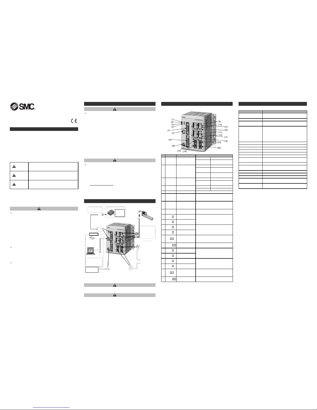
3 Parts Description
PLC
PC
•Controller
•Electric actuator
Note2)
Note2)
Note1)
To
ENC
To
MOT
To CI
To M
PWR
Input/output
signal power
supply
24VDC
Note2)
Note2)
To C
PWR
To
I/O
•Controller setting
software
Product No.: JXC-W1-1
•USB cable
Product No.: JXC-W1-
2
•Power cable for main control
Cable length: 1.5m (Accessory)
Product No.: JXC-C1
•Motor control power
supply connector
(Accessory)
<Applicable wire size>
AWG20 (0.5mm
2
)
•Motor drive power connector
(Accessory)
<Applicable wire size>
AWG16 (1.25mm2)
Motor control and
motor drive power
supply 24 VDC
Note 1) Connected actuators should be ordered separately.
Note 2) PLC, PC and 24VDC power supply should be prepared by the user.
Note) The connector is included.
No.D
isplayDescription
D
etails
1 P
WR
Power supply LED
(green)
OFF Power supply OFF
Green LED is
O
N
Power supply ON
3 USB
U
SB LED
(green)
O
FF
U
SB not connected
Green LED is
O
N
USB connected
4 ALM
Alarm LED
(
red)
OFF No alarm
5 USB Serial communication Connect to a PC using a USB cable.
6 C
PWR
Main control power
s
upply connector
(2 pin)
N
ote)
C
onnect to the PLC using an I/O cable.
7 I/O 1
Parallel I/O connector
(40 pins)
Connect to the PLC using an I/O cable.
8 I/O 2
Parallel I/O connector
(40 pins)
Display the status of the EtherNet/IP
communication.
9 ENC 1
Encoder connector
(16 pins)
Axis 1: Connect the actuator cable.
10 MOT 1
Motor power
connector (6 pins)
Axis 2: Connect the actuator cable.
11 ENC 2
Encoder connector
(16 pins)
Motor control power supply(+), Axis 1
stop(+), Axis 1 unlock(+), Axis 2 stop(+),
Axis 2 unlock(+)
12 MOT 2
Motor power
connector (6 pins)
Axis 1, Axis 2 Motor drive power(+),
common(
-
)
13 CI 1 2
Motor control power
supply connector
N
ote)
14 M PWR 1 2
Motor drive power
connector
Note)
15 ENC 3
Encoder connector
(16 pins)
16 MOT 3
Motor power
connector (6 pins)
17 ENC 4
Encoder connector
(16 pins)
Axis 4: Connect the actuator cable.
18 MOT 4
Motor power
connector (6 pins)
Axis 3: Connect the actuator cable.
19 CI 3 4
Motor control power
supply connector
Note)
Motor control power supply(+), Axis 3
stop(+), Axis 3 unlock(+), Axis 4 stop(+),
Axis 4 unlock(+)
20 M PWR 3 4
Motor drive power
connector
Note)
Axis 3, Axis 4 Motor drive power(+),
common(
-
)
Red LED is ON Alarm condition
2 R
UN
Operating LED
(
green)
O
FF
S
top
G
reen LED is
ON
O
peration by parallel I/O
Green LED is
flashing
Operation by USB
communication
Detail of the controller parts.
•I/O cable
Product No: JXC-C2-∗
To
USB
4 Product Specifications
Basic specifications
I
tem
S
pecifications
N
umber of axes per
c
ontroller
Max. 4-axis
C
ontrolled motor
S
tep motor (servo 24 VDC)
Controlled encoder
I
ncremental phase A/B
(Encoder resolution 800 pulse/rotation)
P
ower supply specification
N
ote1)
M
ain control power supply
Power supply voltage: 24VDC+/
-
10%
M
ax. current consumption: 300 mA
Motor drive and motor control power supply
P
ower supply voltage: 24VDC+/
-
1
0%
Max. current consumption: Depends on connected
a
ctuator.
Note2)
Serial communication
USB2.0 (Full Speed 12Mbps)
M
emory
F
lash ROM and EEPROM
Parallel input 16 inputs (Optically isolated)
P
arallel output
3
2 outputs (Optically isolated)
L
ock control
W
ith forced lock-release terminal
N
ote3)
Cable length
I/O cable: 5 m maximum
A
ctuator cable: 20 m maximum
C
ooling method
N
atural air cooling
Operating temperature
range
0
to 40
o
C
(No freezing)
O
perating humidity range90% RH or less (No condensation)
Storage temperature range-10 to 60oC (No freezing)
S
torage humidity range90% RH or less (No condensation)
I
nsulation resistance
Between the external terminals and case
50MΩ (500 VDC)
W
eight
1050 g (Direct mounting)
1
100 g (DIN rail mounting)
L
ED indicator
P
WR (green), RUN (green), USB (green), ALM (red)
Note 1) Do not use a power supply with "inrush current protection" for the motor
drive power and motor control power supply.
N
ote 2) Power consumption depends on the actuator connected. Refer to the
a
ctuator specifications for further details.
Note 3) Applicable to non-magnetizing lock.
Options
•Controller set up kit
Contents
-Controller Setting Kit
-USB cable
Product No.: JXC-W1
[
]
Main control
power supply
24VDC
•Actuator cable
Part No:
LE-CP-*-
*
(Robotic type cable)
LE-CP-*-*-S
(Standard cable)
Note1)

(2) Grounding
Fit the grounding cable with
crimped terminal between
the M3 screw and
shakeproof washer as
shown below and tighten
the screw.
J
XC-TFT34
Refer to the operation manual on SMC website
(URL http://www.smcworld.com).
6 Power supply connector
The figure below shows how
to mount the controller to the
DIN rail. Hook part A on to the
DIN rail. Press part B on to the
DIN rail and tighten the locking
screws (M5 x 14).
(Appropriate tightening torque:
0.4 to 0.6 Nm)
Locking screw M5 x 14
Part B
Part A
Shakeproof washer
M3 screw
Grounding cable
(with crimped terminal)
Caution
The cable with crimped terminal and shakeproof washer must be
prepared by the user.
The controller must be connected to Ground to reduce noise.
Refer to the operation manual on SMC website
(URL http://www.smcworld.com
).
Caution
Connector specifications
The power supply connector included is shown below.
(1) Main control power supply connector: C PWR
(2) Motor drive power connector: M PWR
Specifications of the cable are as follows.
Use the power cable for main control, JXC-C1.
T
erminalFunction
D
escription
+24V
M
ain control
power supply(+)
P
ower supply(+) for main
control.
24-0V
M
ain control
power supply(
-
)
P
ower supply(
-
)
for main
control.
B
rown
+24V
24-0V
B
lue
T
erminalFunction
D
escription
0V M
otor power(
-
)
Power supply(-) common for
M
24V terminal, C24V terminal,
EMG terminal and LKRLS
t
erminal
M24V Motor power(+)
Motor drive power supply(+) for
A
xis 1 and 2 or Axix 3 and 4.
0
V
M
24V
I
tem
S
pecifications
W
ire size
Stranded wire → AWG20 (0.5mm2)
O
.D. of sheath →ø1.76
W
ire sheath colour
+
24V: Brown
24-0V: Blue
Prepare the electrical wiring according to the following specifications
(to be prepared by the user).
When the wire is inserted into the motor drive power connector, insert
only the stripped part of the wire.
Manufactured by Phoenix Contact
(Part number MSTB2,5/2-STF-5,08)
Item Specifications
A
pplicable wire size
Single, Stranded wire → AWG16 (1.25mm2)
T
he rated temperature of the insulation coating
should be 60
o
C or more.
Stripped wire length
7mm
ø3.4 or less
(3) Motor control power supply connector: CI
Prepare the electrical wiring according to the following specifications
(to be prepared by the user).
Manufactured by Phoenix Contact
(Part number FK-MC0,5/5-ST-2,5)
Item Specifications
Applicable wire size
Single, Stranded wire → AWG20 (0.5mm2)
The rated temperature of the insulation coating
should be 60
o
C or more.
Stripped wire length
8mm
ø2.0 or less
EMG1/EMG3
EMG2/EMG4
LKRLS2/LKRLS4
C24V
LKRLS1/LKRLS3
Terminal Function Description
C24V
Motor control
power supply(+)
Power supply side(+) for motor
control.
EMG1/
EMG3
Stop(+)
Release the stop status(+) of
Axis 1 or Axis 3.
(Normal operation by applying
24V.)
EMG2/
EMG4
Stop(+)
Release the stop status(+) of
Axis 2 or Axis 4.
(Normal operation by applying
24V.)
LKRLS1/
LKRLS3
Unlock(+)
Release the lock status(+) of
Axis 1 or Axis 3.
LKRLS2/
LKRLS4
Unlock(+)
Release the lock status(+) of
Axis 2 or Axis 4.
Do not connect multiple wires into one terminal.
Contact failure or short circuit to adjacent wire may lead to malfunction or
fire.
URL http://www.smcworld.com (Global) http://www.smceu.com (Europe)
Specifications are subject to change without prior notice from the manufacturer.
© 2016 SMC Corporation All Rights Reserved
11 Contacts
AUSTRIA (43) 2262 62280-0
NETHERLANDS
(31) 20 531 8888
BELGIUM (32) 3 355 1464
NORWAY
(47) 67 12 90 20
CZECH REP. (420) 541 424 611
POLAND
(48) 22 211 9600
DENMARK (45) 7025 2900
PORTUGAL
(351) 21 471 1880
FINLAND (358) 207 513513
SLOVAKIA
(421) 2 444 56725
FRANCE (33) 1 6476 1000
SLOVENIA
(386) 73 885 412
GERMANY (49) 6103 4020
SPAIN
(34) 945 184 100
GREECE (30) 210 271 7265
SWEDEN (46) 8 603 1200 HUNGARY (36) 23 511 390
SWITZERLAND (41) 52 396 3131 IRELAND (353) 1 403 9000
UNITED KINGDOM
(44) 1908 563888
ITALY (39) 02 92711
BULGARIA (359) 2 974 4492
ESTONIA (372) 651 0370
ROMANIA
(40) 21 320 5111
LATVIA
(371) 781 77 00
LITHUANIA
(370) 5 264 8126
7
How to order
8 Outline with Dimensions (mm)
9
Maintenance
10 Troubleshooting
Refer to the operation manual on the SMC website
(URL http://www.smcworld.com).
(b) DIN rail mounting
The figure on the right shows
how to mount the DIN rail
mounting brackets.
Secure the DIN rail mounting
bracket using 4 mounting
screws (M5 x 8 mm) 2 on
each side. (Appropriate
tightening torque: 3.0 Nm)
Secure the DIN rail mounting
bracket using 2 locking
screws (M5 x 14 mm), 1 on
each side. Tighten for
approximately 2 threads.
Do not tighten completely.
5
Mounting
(1) Mounting
There are two ways to mount the controller.
(Direct mounting and DIN rail mounting)
Controller mounting methods are shown below.
(a) Direct Mounting with four M5 screws
Mounting screw (M5) 4pcs.
(prepared by user)
Mounting screw M5 x 8
Included with DIN rail
mounting bracket
T
ightening torque: 3.0 (Nm)
Locking screw M5 x 14
Included with DIN rail
mounting bracket
Tightening torque: 0.4 to 0.6 (Nm)
[]
[]
When the wire is inserted into the motor control power supply connector,
insert only the stripped.
 Loading...