

SMC Networks IZN10 Series, IZN10-P Series Operation Manual
Doc. No. IZ※-OML0002-C
OPERATION MANUAL
PRODUCT NAME
:
○ Read this operation manual carefully to
understand before installation and operation.
○ Pay extra attention on the clause concerning the
safety.
○ Keep this operation manual available whenever
necessary.
Ionizer
IZN10 Series MODEL:
- 1 -

INDEX
1. Safety Instructions・・・・・・・・・・・・・・・・・・・・・・・・・・・・・・・・・ 3
2. Specifications ・・・・・・・・・・・・・・・・・・・・・・・・・・・・・・・・・・・・ 5
3. How to Order・・・・・・・・・・・・・・・・・・・・・・・・・・・・・・・・・・・・ 6
4. Mounting
4-1. Precautions for mounting・・・・・・・・・・・・・・・・・・・・・・・・・・・・・ 7
4-2. How to mount・・・・・・・・・・・・・・・・・・・・・・・・・・・・・・・・・・ 9
4-3. Wiring table・・・・・・・・・・・・・・・・・・・・・・・・・・・・・・・・・・・・ 15
4-4. Power supply cable wiring diagram・・・・・・・・・・・・・・・・・・・・・・・・・ 16
4-5. Timing chart・・・・・・・・・・・・・・・・・・・・・・・・・・・・・・・・・・・ 16
5. Functional Explanations ・・・・・・・・・・・・・・・・・・・・・・・・・・・・・・・ 17
6. Outline Dimensions・・・・・・・・・・・・・・・・・・・・・・・・・・・・・・・・・ 18
7. Maintenance
7-1. Precautions for maintenance・・・・・・・・・・・・・・・・・・・・・・・・・・・・ 19
7-2. How to maintain electrode needle・・・・・・・・・・・・・・・・・・・・・・・・・・ 20
- 2 -
1. Safety instructions
These safety instructions are intended to prevent hazardous situations and/or equipment damage. These
instructions indicate the level of potential hazard by labels "Caution," "Warning" and "Danger" to ensure
safety. be to observe ISO4414, JIS B8370 and other safety precautions.
CAUTION Operator error could result in injury or equipment damage.
!
WARNING Operator error could result in serious injury or loss of life.
!
DANGER In extreme conditions, there is a possibility of serious injury or loss of life.
!
1) ISO 4414: Pneumatic fluid power – Recommendation for application of equipment to transmission and
control systems
2) JIS B 8370: Rule for Pneumatic System
!
WARNING
1. The compatibility of equipment is the responsibility of the person who designs the system or
decides its specifications.
Since the products specified here are used in various operating conditions, their compatibility with the
specific system must be based on specifications or analysis and/or tests to meet your specific requirements.
The expected performance and safety assurance will be the responsibility of the person who has determined
the compatibility of the system. This person should continuously review the suitability of all items specified,
referring to the latest catalog information with a view to giving due consideration to any possibility of
equipment failure when configuring a system.
2. Only trained personnel should operate machinery and equipment.
This product generates high voltage, so it can be dangerous if an operator is unfamiliar with it. Assembly,
handling or repair of systems should be performed by trained and experienced operators.
3. Do not service machinery/equipment or attempt to eliminate components until safety is
confirmed.
1) Inspection and maintenance of the machinery and equipment should be performed after confirmation of
safety such as grounding, prevention of electric shock and prevention of other types of injury.
2) When equipment is to be eliminated, confirm the safety process as mentioned above. Cut air pressure
supply and electric power supply that are the energy source for the equipment, and exhaust all residual
compressed air in the system.
3) Before machinery/equipment is re-started, take measures to prevent short circuit etc. with care.
4. Contact SMC if the product is to be used in any of the following conditions.
1) Conditions and environments beyond the given specifications, or if product is used outdoors.
2) Installation on equipment in conjunction with atomic energy, railway, air navigation, vehicles, medical
equipment, food and beverages, recreation equipment, emergency stop circuits, clutch and brake
circuits in press applications, or safety equipment.
3) An application which has the possibility of having negative effects on people, property, or animals
requiring special safety analysis.
- 3 -
WARNING
!
1. The ionizer (hereinafter referred to as the “product”) is intended to be used for the general FA devices.
If other applications (especially those indicated in 4 on page 2) are used, contact SMC before use.
2. Use under specified voltage and temperature.
Voltage out of specification may cause malfunction, breakage, electric shock or fire.
3. Use clean compressed air for fluid.
Do not use inflammable or explosive gas for fluid. It may cause fire or explosion. When fluid other than
compressed air is used, contact a SMC service representative.
4. The product doesn’t incorporate explosion-proof construction.
Do not use this product in a place where a dust explosion might be triggered or inflammable or explosive
gas is present. It may cause fire.
!
CAUTION
1. The product has not been washed.
Flush and confirm its purification level before bringing into a clean room.
Selection
Handling
!
CAUTION
1. Do not drop, hit or otherwise apply excessive impact (10 G or more) when handling.
Though the product itself doesn’t break, the inside construction may be broken and cause malfunction.
2. When cable is mounted or removed, pinch the modular plug claw with fingers and insert or take out the
plug vertically. If mounted or removed in an inappropriate direction, the mounting part of the modular jack
may be damaged and cause operation failure.
- 4 -
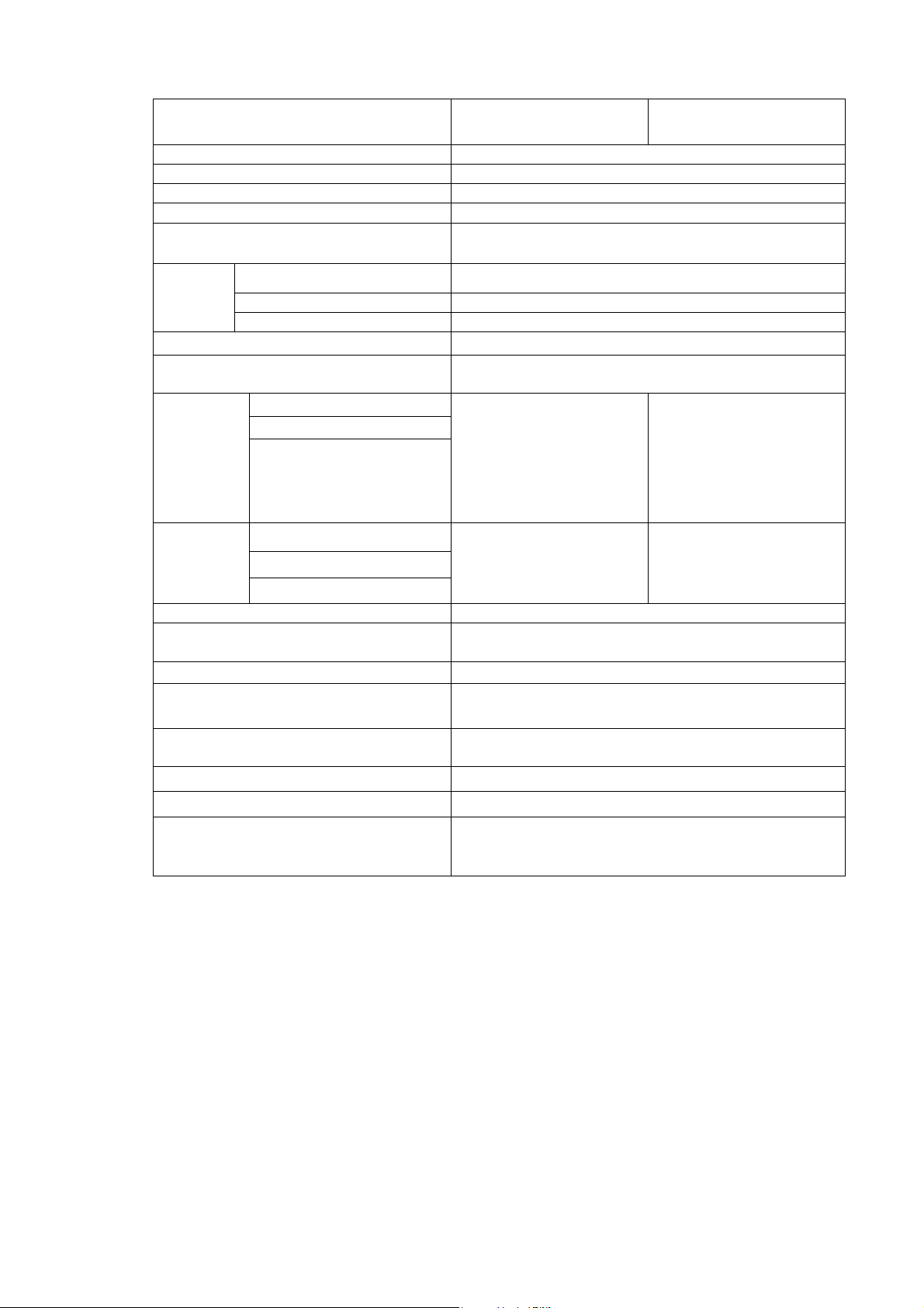
2. Specifications
Model number of ionizer IZN10-□□
(NPN)
Ion generating method Corona discharge type
Voltage applying method High frequency AC type
Discharge output
Ion balance
Ozone generated amount
Air
purge
Note 1)
Note 2)
Note 3)
Fluid
Operating pressure
Note 4)
2500V
±10 V at max.
0.03 ppm (0.05 ppm for energy saving charge
elimination nozzle)
Air (clean and dry)
0.05 MPa~0.7 MPa
Connected tube diameter 6 and 1/4 inch
Power supply voltage
Current consumption
Discharge stop signal
Reset signal
Input
signal
External switch signal
Discharge signal
Output
signal
Error signal
Maintenance signal
(When input and output signals are not used)
GND to connection
The voltage to turn on is 0.6V
or less.
Current consumption: 5 mA or
less
Max. load current: 40 mA
Residual voltage: 1 V or less
(with load current of 40 mA)
Max. applied voltage: DC 28
V
24VDC±10%
80 mA
The voltage to turn on is from
Residual voltage: 1 V or less
Effective charge eliminating distance 20~500 mm
Ambient temp.
0~55oC
Fluid temp.
Ambient humidity
35~65% RH(With no condensation)
Body: ABS, Stainless Nozzle: Stainless
Material
Vibration resistance
Impact resistance
Weight
Durable to 50 Hz with amplitude 1 mm for 2 hours in
Electrode needle: Tungsten
each X, Y and Z direction
10 G
120 g
CE (EMC directive: 89/336/EEC, 92/31/EEC、
Applicable standard/directive
93/68/EEC, 2004/108/EC, Low-voltage directive:
73/23/EEC, 93/68/EEC)
Note 1) This is the value when measured by a probe with 1,000 MΩ and5 pF.
Note 2) This specification is applicable when the distance between the charged object and the
ionizer is 100 mm using the power saving static elimination nozzle, and the air purge
pressure is 0.3 MPa.
Note 3) This is the value from which the background is drawn with a distance of 300 mm from the
front face of the nozzle.
Note 4) Charge elimination is not available without air purge. Also, without air purge, internal
ozone concentration will increase and adversely affect the product and peripheral
equipment.
IZN10-□□P
(PNP)
+24V to connection
+19V to the
power supply voltage.
Current consumption: 5 mA
or less
Max. load current: 40 mA
(with load current of 40 mA)
- 5 -
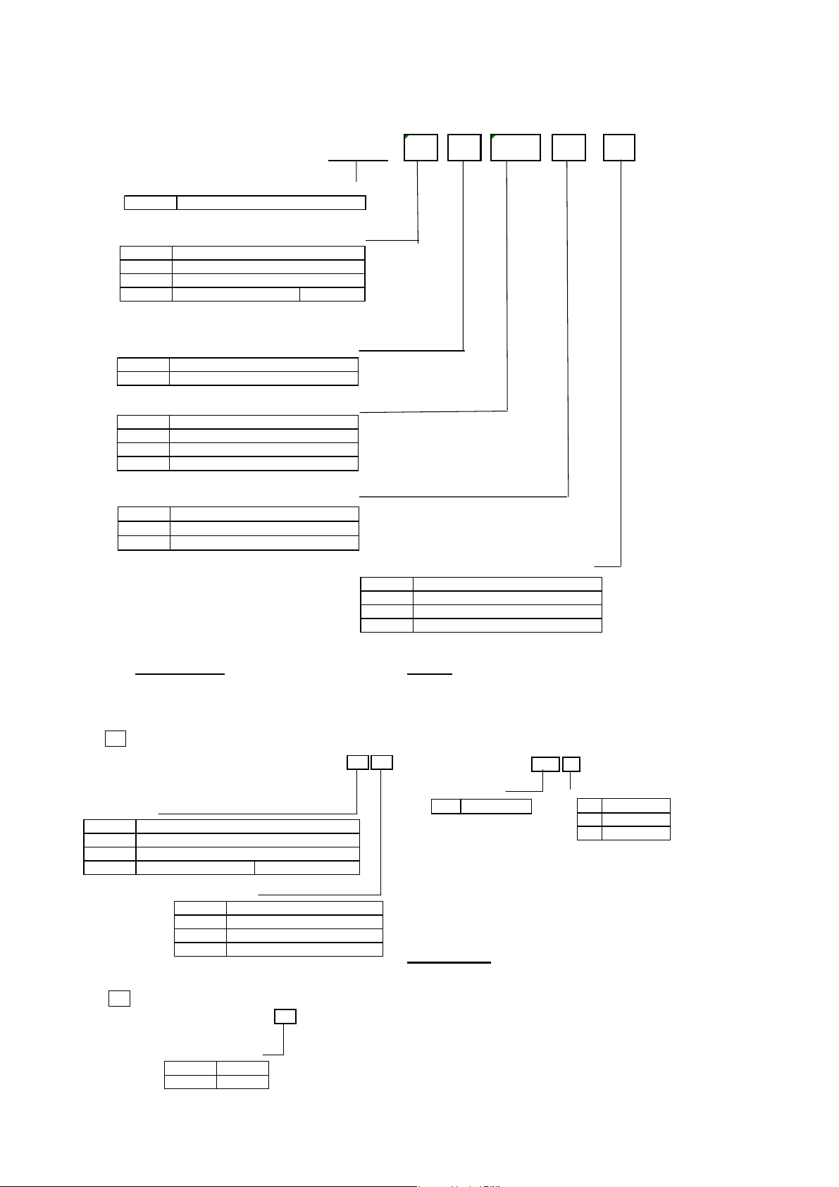
3. How to Order
A
d
Series name
IZN10 High frequency AC nozzle type
IZN10 - 01 P 06 Z - B1
Nozzle shape
NIL
Energy saving charge elimination nozzle
01
02
11 Piping female Note 1) Rc1/8
Output specification
NIL NPN
PPNP
Piping diameter
06 f6: metric
07 f6.35
16 f6: metric (elbow)
17 f6.35
Power s upply cable
NIL 3m
Z 10m
N Not provided
Type
Large flow nozzle
1/4"): inch
(
1/4"): inch (elbow)
(
Bracket
NIL Not provided
B1 L-bracket
B2 Swing brac ket
B3 DIN rail mounting bracket
Service parts Option
Electrode needle assembly Manifold mounting parts set
IZN10-NT Hexagon socket head bolts, s pacer and hexagon nuts are included.
・
B
Body Assembly
・IZN10 - A002 - 01 06
Noz z le shape
NIL
01
02
11 Piping female Note 1) Rc1/8
Energy s aving charge elim ination noz zle
Piping diamete r
B
Cartridge As sembly ・
・IZN10 - A003 - P
Output specification
NIL NPN
PPNP
Type
Large flow nozz le
06 f6: metric
07 f6.35(1/4"): inch
16 f6: metric (elbow)
17 f6.35(1/4"): inch (elbow)
The ionizer and L-bracket or DIN rail mounting need to be ordered separately.
Manifold mounting parts
IZN10 - ES 2
・
Mounting pitch
ES 17mm
Electrode needle cleaning kit/IZS30-M2
Number of manifol
2 2 stations
3 3 stations
4 4 stations
ccessories
Power supply cable
IZN10-CP(3m) ・IZN110-CPZ(10m)
Bracket
L-bracket/IZN10-B1
・
Swing brac ket/IZN10-B2
・
DIN rail mounting bracket/IZN10-B3
・
- 6 -
 Loading...