

SMC Networks ITV2000 series, ITV2090 series, ITV3000 series Installation And Maintenance Manual
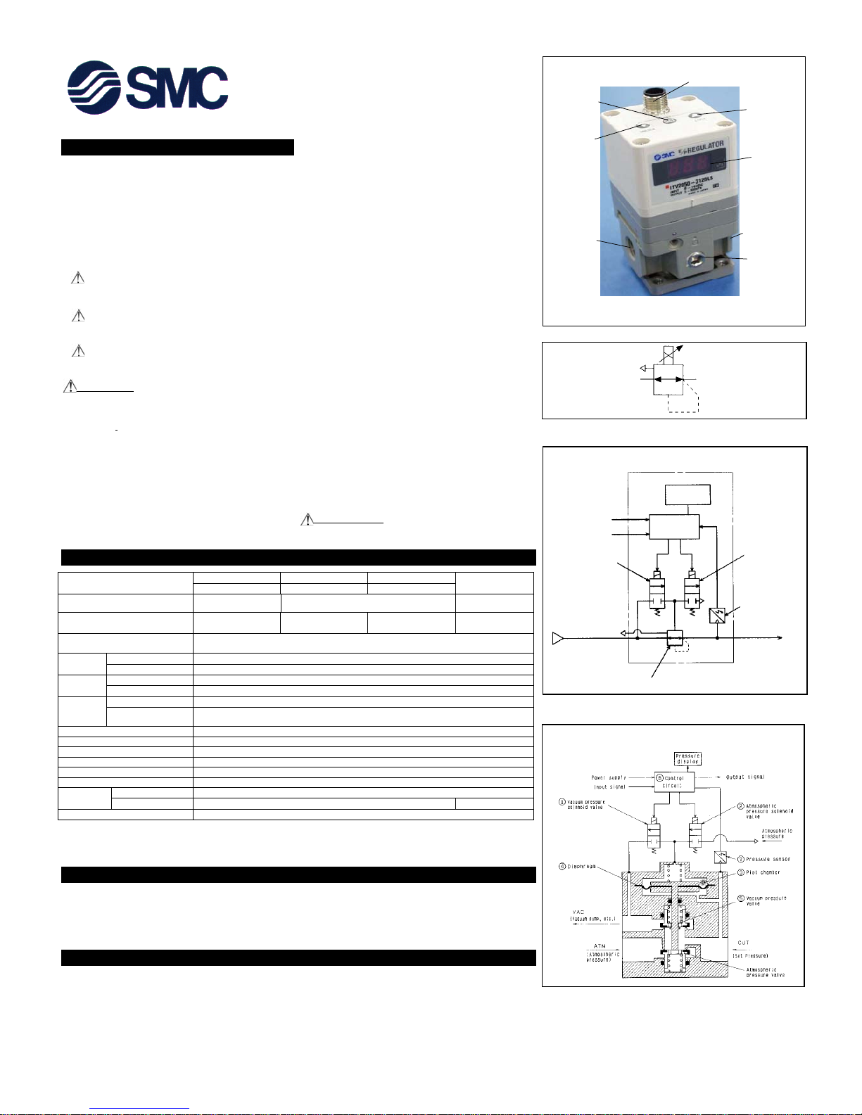
Fig 1
Fig 2
Safety Instructions
These safety instructions are intended to prevent a hazardous
situation and / or equipment damage. These instructions indicate the
level of potential hazard by label of “Caution” “Warning”, or
“Danger”. To ensure safety, be sure to observe ISO 4414 (Note 1), JIS
B 8370 (Note 2) and other safety practices.
(Note1) ISO 4414: Pneumatic fluid power-Recommendations for the
application of equipment to transmission and control systems.
(Note 2) JIS B 8370 : Pneumatic system axio
m
CAUTION : Operator error could result in injury or
equipment damage.
WARNING : Operator error could result in serious injury
or loss of life.
DANGER : In extreme conditions, there is a possible result
of serious injury or loss of life.
WARNING
1. The compatibility of pneumatic equipment is the responsibility of
the person who designs the pneumatic system or decides its
specifications.
Since the products specified here are used in various operating
conditions, their compatibility for the specific pneumatic system
must be based on specifications or after analysis and/or tests to
meet your specific requirements.
2. Only trained personnel should operate pneumatically operated
machinery and equipment.
Compressed air can be dangerous if an operator is unfamiliar with
it. Assembly, handling or repair of pneumatic systems should be
performed by trained and experienced operators
.
3. Do not service machinery / equipment or attempt to remove
component until safety is confirmed.
1) Inspection and maintenance of machinery / equipment should
only be performed after confirmation of safe locked-out control
positions.
2) When equipment is to be removed, confirm the safety process as
mentioned above. Switch off air and electrical supplies and
exhaust all residual compressed air in the system.
3) Before machinery / equipment is re-started, ensure all safety
measures to prevent sudden movement of cylinders etc. (Bleed
air into the system gradually to create back-pressure, i.e.
incorporate a soft-start valve.)
4. Contact SMC if the product is to be used in any of the following
conditions .
1) Conditions and environments beyond the given specifications, or if
product is used outdoors.
2) Installation on equipment in conjunction with atomic energy,
railway, air navigation, vehicles, medical equipment, food and
beverage, recreation equipment, emergency stop circuits, press
applications, or safety equipment.
3) An application which has the possibility of having negative effects
on people, property, or animals requiring special safety analysis.
CAUTION
Ensure that the air supply system is filtered to 5 micron.
Specifications
Operation Principal ITV2000(Fig 3)
When the input signal increases, the supply solenoid valve ① turns on and the exhaust solenoid valve ② turns off. Supply pressure is
passed to the pilot valve ③ through the supply solenoid valve. The pilot valve will open the main valve allowing partial supply pressure to
pass to the out port.
The pressure sensor ④ will provide output pressure feedback to the control circuit ⑤. The control circuit will balance the input signal and
output pressure to ensure that the output pressure remains proportional to the input signal.
Operation Principal ITV2000(Fig 4)
When the input signal increases, the vacuum solenoid valve ① turns ON, and the atmospheric pressure solenoid valve ② turns OFF.
Because of this, VAC and pilot chamber ③ are connected, the pressure in the pilot chamber ③ becomes negative and acts on the top of the
diaphragm. As a result, the vacuum pressure valve ⑤ which is linked to the diaphragm ④ opens, VAC and OUT are connected, and the set
pressure becomes negative.
This negative pressure feeds back to the control circuit ⑧ via the pressure sensor ⑦. Then, a correct operation works until a vacuum
pressure proportional to the input signal is reached, and a vacuum pressure is obtained which is always proportional to the input signal.
Fig 3
Fig 4
In
I
(
(
(
Down Key
Up- Key
A
ir supply por
t
Gauge port
A
ir out let port
LED disp lay
Elec tri cal c onnect or
Set Key
Installation and Maintenance Manual
Series ITV2000,3000,2090
Electro-Pneumatic Regulator
For future reference, please keep this manual in a safe place
This manual should be read in conjun ction with the current catalogue.
Symbol
Pressur
e
Di s p l a
y
⑤
Cont r ol
cir cu it
Power suppl
y
Input signal
①
Supply solenoi
d
valve
SUP
OUT
④
Pressur e sensor
②
Exh au s t
solen oid val ve
④
Pi lot v al ve
ITV2000,30000
ITV201
□
ITV203
□
ITV205
□
Mod e l
ITV301
□
ITV303
□
ITV305
□
ITV209
□
Max. Supply Pr essure 0.2MPa (0.2kgf/cm2)1.0MPa (10.2kgf/cm
2
)
-101kPa
(-760mmHg)
Set t in g Pr es su r e Ra ng e
0.005~0.1MPa
(0.05~1.0kgf/cm
2
)
0.005~0.5MPa
(0.05~5.1kgf/cm2)
0.005~0.9MPa
(0.05~9.2kgf/cm2)
-1.3~-80kPa
(-10~-600mmHg)
Su pp ly vo lt ag e
Supply voltage 24VDC Type : 0.12A or less
Sup p ly v o lt a ge 1 2~15VDC Type : 0.18A or less
Cur rent Type (Note 1)
4~20mADC, 0~20mADC
put Signal
Vo lt a ge Typ e
0~5VDC, 0~10VDC
Cur rent Type
250Ω or less
Input
mpedance
Vo lt a ge Typ e
APPROX. 6.5k
Ω
Analog Output
1~5VDC Load Impedance : more th an 1k
Ω
(Note 2)
Out p u t
Si g n a l
Switch Output
NPN Open Collector Type : 30V, 30mA
PNP Open Collector Type : 30mA
Linear ity
±
1 % F.S. or less
Hyster esis 0. 5 % F.S. or less
Repeatability
±
0.5 % F.S. or less
Sensitivity 0.2 % F.S. or less
Temperat ure Characteri stics
±
0.12 % F.S. or less /
℃
Prot ection Str uctur e Main unit : Equivalent to IP65 Cable connect or : IP67
Acc u r ac y
±
3%F.S.
Display o f
Pr ess ur e
Min. Unit MPa : 0.01, kgf/cm
2
: 0.01, bar : 0.01, PSI : 0.1 (note3), kPa : 1 kPa : 1
Ambient and flui d temperat ure
0~50℃ (without condensation)
Note 1) Two wire control, 4 to 20mADC and 0 t o 20mADC ar e not av ailabl e. Suppl y volt age of 12~15VDC or 24VDC is required.
Note 2 ) Please make a sel ectio n of either Analog output or Swit ch outp ut. Also sel ect eit her NPN or PNP output wh en Switch o utput is selected.
Note 3) 1PSI is the minimum unit on ITV205□ or ITV305
□
ITV2090
CAUTION
1. If the electrical supply fails, settings are ‘held’ for a short period.
2. If the air pressure fails with power ‘on’ the solenoid will ‘flutter’.
3. If the monitor output functions is not used, ensure that the wire is
totally insulated.
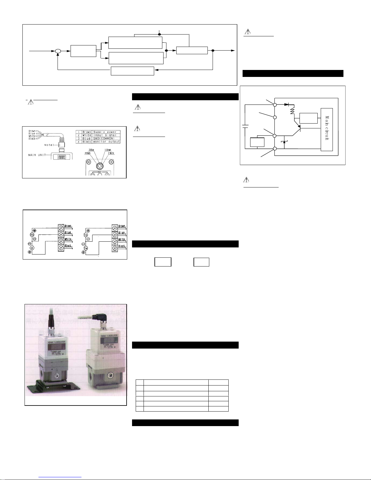
Fig 5
PNP Circuit
Note: If the supply exceeds 30mA the sensor will output to the LED
display (Fig 1) and show ‘Er 5’.
CAUTION
Wiring
Connect the cable to the connector on the main unit as shown in the
following diagram. Take precautions as incorrect wiring will damage the
unit. Use a DC power supply capable of supplying the necessary power
requirements with minimal ripple.
Note: The right angle type connector extends to the left side (over the
supply port side).
Wiring diagram
Setting the Regulator
CAUTION
As soon as the ‘set’ key is operated minimum/maximum pressure will be
present at the outlet port.
CAUTION
As soon as primary pressure is applied to the regulator minimum pressure
will be present at the outlet port.
・Release ‘lock key’ (Fig 1) as explained in section ‘Function of key-lock’
・To set minimum pressure (display shows F-1 Fig 1) use up/down keys
(Fig 1) to set minimum pressure, press ‘set’ key(Fig 1) to ‘lock ’
setting.
・To set maximum pressure(display shows F-2 Fig 1) use up/down keys
(Fig 1) to set maximum pressure, press ‘set’ key(Fig 1) to ‘lock’
setting.
・To set switch output 1 (display shows P-1 Fig 1) use up/down keys to set
switch output, press ‘set’ key(Fig 1) to ‘lock’ setting.
・To set switch output 2 (display shows P-2 Fig 1) use up/down keys to set
switch output.
Note 1:If the above sequence of events has been followed correctly, the
settings will complete automatically.
Note 2:If only setting minimum pressure, when pressure is ‘set’, pressing
the set button once more will ‘skip’ to the next step.
Current signal type Voltage signal type
Vs : Power supply 24VDC
12VDC
A : Input Signal 4 to 20mADC
O to 20mADC
Vs : Power supply 24VDC
12VDC
Vin : Input Signal 0 to 5VDC
O to 10VDC
Fig 6
Function of Key-Lock
With input signal applied
▽ Push ‘down’ key (Fig 1) for larger than 2 seconds. Display (a)
flashes ’lock’.
1. Push ‘set’ key (Fig 1) lock automatically releases.
Note: Push ‘down’ key (Fig 1) again to cancel operation.
2. Key Lock Release
1. Push down on ’unlock’ (Fig 1) key for longer than 2 seconds.
2. Key-lock will release.
Note: To cancel push ‘lock’ key (Fig 1).
3. To Lock
1. Push down on ‘up’ △ (Fig 1) for longer than 2 seconds.
2. Led will flash ‘unL’ (unlock).
3. Push ‘set’ key (Fig 1) to lock.
Note: To cancel push ‘down’ key (Fig 1).
Function of the ‘Error’ Display
If an abnormality is detected by the ITV2000, 3000, 2090, the LED display
(Fig 1) will show ‘Er’ followed by a code number. Isolate the power supply
and ascertain and solve the problem. Re-instate power supply after
correcting fault.
Error codes are as follows:
Straight Type Connector Right Angle Type Connector
Fig 7
Reset Function
Push up and down keys (Fig 1) together for longer than 3 seconds. Display
(Fig 1) shows ‘RES’. Release keys, minimum, maximum pressures, switch
outputs P1 and P2 are reset to start condition.
CAUTIONS
1. This product (ITV2000, 3000, 2090) is pre-set at the factory and
must not be dismantled by the user. Contact your local SMC office
for advice.
2. Ensure, when installing this product, that is kept clear of power
lines to avoid noise interference.
3. Ensure that load surge protection is fitted when inductive loads are
present (i.e. solenoid, relay etc.).
4. Ensure precautions are in place if the product is used in a ‘free flow
output ’ condition. All will continue to flow continuously.
5. Do not use a lubricator on the input side of this product. If
lubrication is necessary, place the lubricator on the ‘output’ side.
6. Ensure all air is exhausted form the product before maintenance.
7. Length of connector cable shall be 10m or less.
When you enquire about the product, please contact the following
SMC Corporation:
In
B
Blue
load
Black
White
senso r
Brown
M
a
i
n
c
i
r
c
u
i
t
-
p
ut signal
⑤ Co n t r o l
cir cuit
① Supply solenoid valve
(
Vac u um so l .
)
② Exhaust solenoid valve
(Atmospheric sol.)
③ Pilot valve
S u p p ly p r e s s u r e (V A C )
④ Pressure sensor
lock line char t
Out pu t
pressure
※ ( ) : IT V 2 0 9 0 T Y P E
b
a
PHONE PHONE
ENGLAND 01908-563888 TURKEY 212-2211512
ITALY 02-92711 GERMANY 6103-402-0
HOLLAND 020-5318888 FRANCE 01-64-76-10-00
SWITZERLAND 052-34-0022 SWEDEN 08-603 07 00
SPAIN 945-184100 AUSTRIA 02262-62-280
902-255255 IRELAND 01-4501822
GREECE 01-3426076 DENMARK 87 38 87 00
FINLAND 09-68 10 21 NORWAY 67-12 90 20
BELGUIM 03-3551464 POLAND 48-22-6131847
No Content Display
1 Input Signal Outside Spec. Er 1
2 EEProm Reading / Writing Error Er 2
3 Memory Reading / writing Error Er 3
4 Solenoid Valve Fault Er 4
5 Switch Output Over-Current Er 5
 Loading...