

Page 1
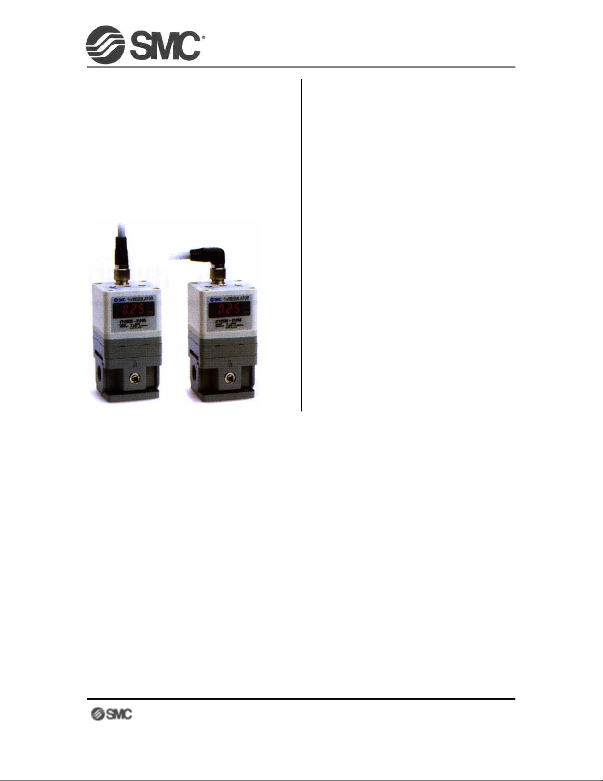
MICROPROCESSOR-CONTROLLED
E-P REGULATOR
ITV2000
Microprocessor-Controlled Electro-Pneumatic Regulator ITV2000
EASY PROGRAMMING GUIDE
CONTENTS:
1. LAYOUT IDENTIFICATION
2. WIRING
3. INPUT SIGNAL
4. KEY LOCK FUNCTION
5. SET POINT PROGRAMMING
6. ADJUSTING MINIMUM &
M
AXIMUM PRESSURES
7. MONITOR OUTPUT
8. ERROR MESSAGES
9. SPECIFICATIONS
Page 1
last updated 11/03/03 10:05 AM
Page 2
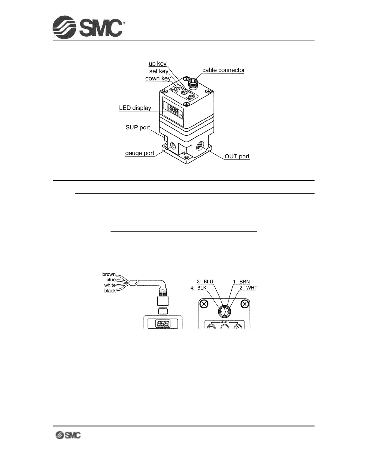
LAYOUT IDENTIFICATION
WIRING
Please be careful when connecting the four c able wires. Im proper wiring will dam age the
internal circuitry.
Microprocessor-Controlled Electro-Pneumatic Regulator ITV2000
EASY PROGRAMMING GUIDE
PIN # WIRE COLOR DESCRIPTION
1 Brown Supply Voltage
2 White Input Signal
3 Blue Ground
4 Black Monitor Output
.
Page 2
last updated 11/03/03 10:05 AM
Page 3
INPUT SIGNAL
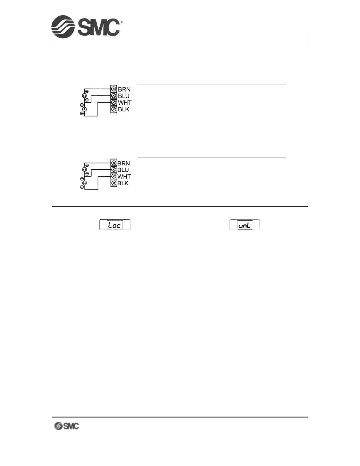
• CURRENT SIGNAL TYPES (ITV20-0, ITV20-1)
Microprocessor-Controlled Electro-Pneumatic Regulator ITV2000
EASY PROGRAMMING GUIDE
Supply Voltage VS Input Signal A
• VOLTAGE SIGNAL TYPES (ITV20-2, ITV20-3)
KEYLOCK FEATURE
The ITV has a key lock feature, allowing the user to disable the setting k eys. This
is helpful in preventing unauthorized setting changes. By default, the keys are locked
when power is turned on. The keys must be unloc ked to modify the setting information.
The display will show
24VDC (ITV200)
12VDC (ITV201)
Supply Voltage VS Input Signal VIN
24VDC (ITV200)
12VDC (ITV201)
locked unlocked
LOC if a key is pressed while the keys are locked.
4~20mA (ITV20-0)
0~20mA (ITV20-1)
0~5VDC (ITV20-2)
0~10VDC (ITV20-3)
TO UNLOCK:
¬ Press and hold the down key for 2 seconds or longer. The display will blink LOC.
Press the set key to unlock the keys, or
® Press the up key to cancel.
TO LOCK:
¬ Press and hold the up key for 2 seconds or longer. The display will blink UNL.
Press the set key to lock the keys, or
® Press the down key to cancel.
Page 3
last updated 11/03/03 10:05 AM
Page 4

PROGRAMMING THE SET-POINTS
Microprocessor-Controlled Electro-Pneumatic Regulator ITV2000
EASY PROGRAMMING GUIDE
3CAUTION:
1. UNLOCK THE KEYPAD
• Press and hold the down key for 2 seconds or longer. The display will blink LOC.
• Press the set key to unlock the keys.
• Press the SET key to continue to the next step.
2. SET THE MINIMUM PRESSURE (F_1)
• Press the UP and DOWN keys until the display shows the desired minimum pressure.
• Press and release the SET key to continue to the next step.
3. SET THE MAXIMUM PRESSURE (F_2)
• Press the UP and DOWN keys until the display shows the desired maximum
• Press and release the SET key to continue to the next step.
4. SET THE MONITOR PRESSURE (P_1)
• Press the UP and DOWN keys until the display shows the desired monitor pressure.
• Press and release the SET key to continue to the next step.
When setting the minimum pressure and maximum pressure values, the new values take
effect as soon as the SET key is pressed. Use caution to avoid damage or injury.
pressure.
5. SET THE MONITOR PRESSURE (P_2)
• Press the UP and DOWN keys until the display shows the desired monitor pressure.
• Press and release the SET key to finish the setup.
• The display returns to the current pressure.
Page 4
last updated 11/03/03 10:05 AM
Page 5
Microprocessor-Controlled Electro-Pneumatic Regulator ITV2000
EASY PROGRAMMING GUIDE
ADJUSTING THE MINIMUM AND MAXIMUM PRESSURES
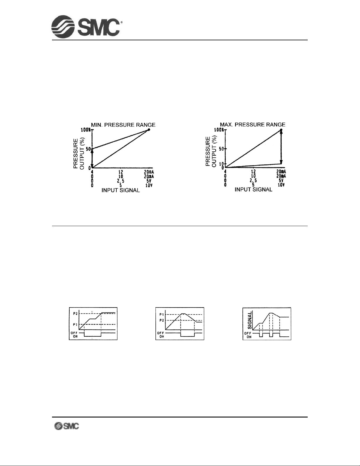
The ITV allows the user to customize the minimum pressure (zero point) at 0% input
signal and the maximum pressure (span) at 100% input signal. The minimum pr es sur e can be set
as low as 0% and as high as 50% of the full span. The maximum pressure can be set as low as
10% and as high as 100% of the full span.
For example, an ITV203 c ould be set to output 35 PSI at 0% input signal, and 43 PSI at
100% input signal (there must be at least 8 PSI separation). Sim ilarly, the same ITV203 could be
set to output 0 PSI at 0% input signal, and 8 PSI at 100% input signal.
minimum pressure (zero) adjust maximum pressure (span) adjust
MONITOR OUTPUT
The ITV is available with one of three different monitor output signals:
• ANALOG (ITV20-1): Linear analog pressure monitor signal (1~5VDC). Input impedance:
100KΩ or greater
• NPN DIGITAL (ITV20-2): NPN open-collector output. Maximum load current: 30mA
• PNP DIGITAL (ITV20-3): PNP open-collector output. Maximum load current: 30mA
The NPN and PNP digital monitor outputs can be set to function in one of three different ways:
comparator mode hysteresis mode self-diagnostic mode
when P1<P2 when P1>=P2 when P1=P2=0
• The output is on whenever
the outlet pressure is
greater than P1 but less
than P2.
• The output comes on once
the outlet pressure
reaches P1. The output
will remain on until the
outlet pressure drops to
P2.
• The output is on whenever
the outlet pressure equals
the commanded pressure.
The output is off whenever
the input signal changes.
ERROR MESSAGES
Page 5
last updated 11/03/03 10:05 AM
Page 6
Microprocessor-Controlled Electro-Pneumatic Regulator ITV2000
EASY PROGRAMMING GUIDE
ERROR # DESCRIPTION
1
2
3
4
0
*Simultaneously press and hold the UP and DOWN keys for 3 seconds or longer to reset.
Input signal exceeds the input signal range
EPROM read/write error
Memory read/write error
Internal solenoid valve malfunction
Other
LED DISPLAY
ER1
ER2
ER3
ER3
ER0
SPECIFICATIONS
Supply Pressure [set pressure + 14.5psi] to 145psi
Output Pressure 0.725~14.5psi (ITV201)
0.725~72.5psi (ITV203)
0.725~130.5psi (ITV205)
Maximum Flow 52.5 SCFM
Supply Voltage 24VDC±10% (ITV200)
12VDC±10% (ITV201)
Input Signal 4~20mADC (ITV20-0)
0~20mADC (ITV20-1)
0~5VDC (ITV20-2)
0~10VDC (ITV20-3)
1
Input Impedance
Linearity ±1% FS
Hysteresis 0.5% FS
Repeatability ±0.5% FS
Monitor Output 1~5VDC analog
250Ω or less (ITV20-0 & -1)
approx. 6.5KΩ (ITV20-2 & -3)
transistor (NPN, PNP), max. 30mA
1
Except ITV201, which is 29PSI.
Page 6
last updated 11/03/03 10:05 AM
Page 7
 Loading...