

SMC Networks ITV10*0-CC****-Q Series,ITV20*0-CC****-Q Serie,ITV30*0-CC****-Q Series Installation And Maintenance Manual
ITV2-CC-TFM133
Installation and Maintenance Manual
Electro-Pneumatic Regulator (for CC-Link)
ITV10*0-CC****-Q (old number ITV10*0-X305),
ITV20*0-CC****-Q (old number ITV20*0-X305),
ITV30*0-CC****-Q (old number ITV30*0-X305)
1 Safety Instructions
This manual contains essential information for the protection of users and
others from possible injury and/or equipment damage.
• Read this manual before using the product, to ensure cor rect handling,
and read the manuals of related apparatus before use.
• Keep this manual in a safe place for future reference.
• These instructions indicate the level of potential hazard by label of
“Caution”, “Warning” or “Danger”, followed by important safety
information which must be carefully followed.
• To ensure safety of personnel and equipment the safety instructions in
this manual and the product catalogue must be observed, along with
other relevant safety practices.
Caution
Indicates a hazard with a low level of risk, which if
not avoided, could result in minor or moderate
injury.
Warning
Indicates a hazard with a medium level of risk,
which if not avoided, could result in death or
serious injury.
Danger
Indicates a hazard with a high level of risk, which if
not avoided, will result in death or serious injury.
• Electromagnetic compatibility:
This product is class A equipment intended for use in an industrial
environment. There may be potential difficulties in ensuring
electromagnetic compatibility in other environments due to conducted as
well as radiated disturbances.
• The compatibility of pneumatic equipmen t is the responsibility of
the person who designs the pneumatic system or decides its
specifications.
Since the products specified here can be used in various operating
conditions, their compatibility with the specific pneumatic system must
be based on specifications or after analysis and/or tests to meet specific
requirements.
• Only trained personnel should operate pneumatically operated
machinery and equipment.
Compressed air can be dangerous if an operator is unfamiliar with it.
Assembly, handling or repair of pneumatic systems should be performed
by trained and experienced personnel.
• Do not service machinery/equipment or attempt to remove
components until safety is confirmed.
• Inspection and maintenance of machinery/equipment should only be
performed after confirmation of safe locked-out control positions.
• When equipment is to be removed, confirm the safety process as
mentioned above. Switch off air and electrical supplies and exhaust all
residual compressed air in the system.
• Before machinery/equipment is re-started, ensure all safety measures
to prevent sudden movement of cylinders etc. (Supply air into the
system gradually to create back pressure, i.e. incorporate a soft-start
valve).
• Do not use this product outsi de of the specificatio ns. Contact SMC
if it is to be used in any of the following conditions:
• Conditions and environments beyond the given specifications, or if the
product is to be used outdoors.
• Installations in conjunction with atomic energy, railway, air navigation,
vehicles, medical equipment, food and beverage, recreation equipment,
emergency stop circuits, press applications, or safety equipment.
• An application, which has the possibility of having negative effects on
people, property, or animals, requiring special safety analysis.
• Ensure that the air supply system is filtered to 5 microns.
2 Specifications
Model ITV*010 ITV*030 ITV*050 ITV2090
Min. supply pressure (Set pressure) + 0.1 MPa
(Set pressure)
–13.3 kPa
Max. supply pressure 0.2 MPa 1.0 MPa 1.0 MPa -101 kPa
Set pressure range
0.005 ~
0.1 MPa
0.005 ~
0.5 MPa
0.005 ~
0.9 MPa
-1.3 ~ -80 kPa
Supply voltage 24 VDC±10%
Current consumption Max. 140 mA
Input/output data 12 bit/12 bit (data 4095 corresponds to 100%F.S.)
Linearity Max. ±1%F.S.
Hysteresis Max. 0.5%F.S.
Repeatability Max. ±0.5%F.S.
Sensitivity Max. 0.2%F.S.
Temperature characteristics
Max. ±0.12%F.S./°C
Operating temperature 0~50°C (without condensation)
Protection structure IP65
Model ITV10*0 ITV20*0 ITV30*0
Size (mm) 50×50×161 50×50×183
66×66×204
Weight (No option) 330 g 430 g 730 g
Table 1.
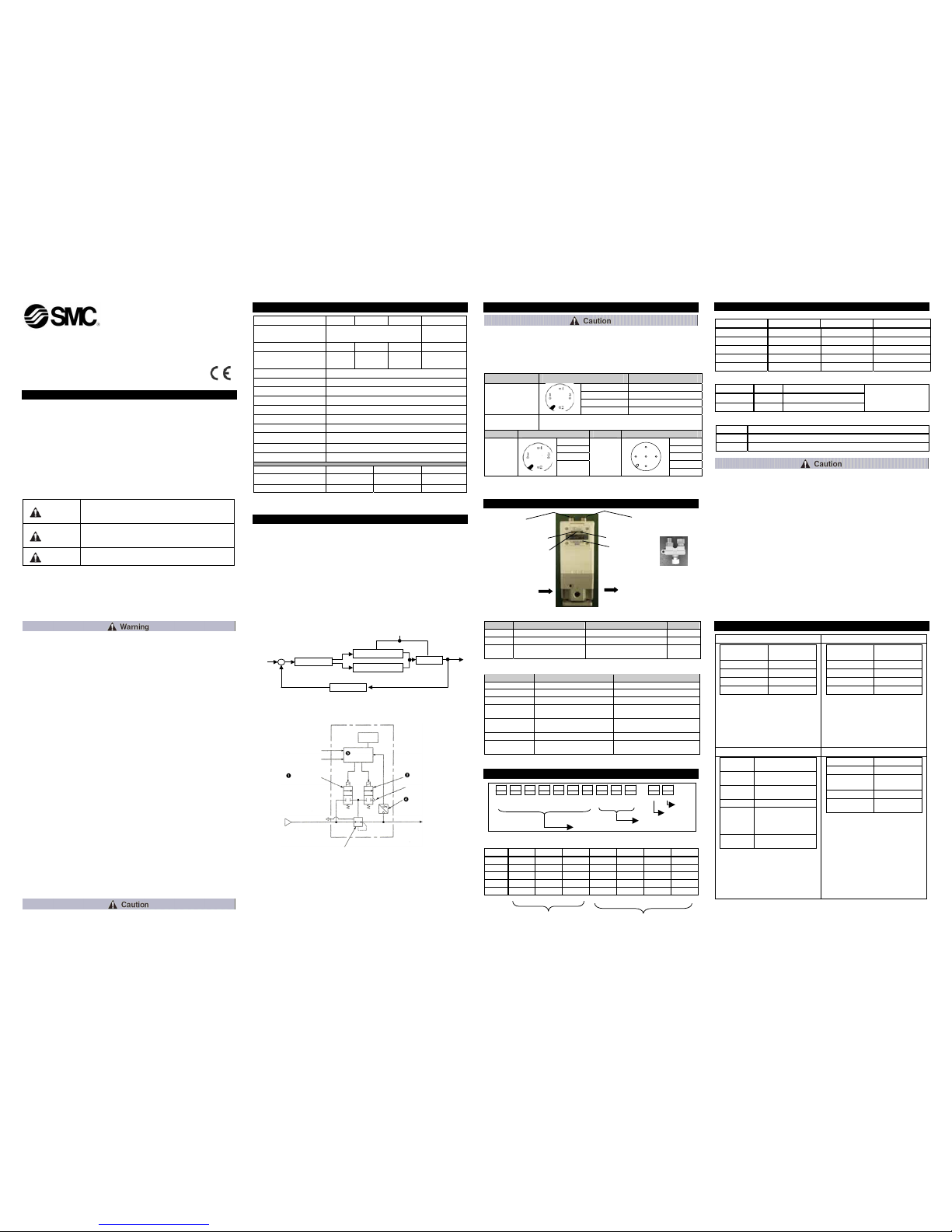
3 Operation Principle
When the input signal increases the supply solenoid valve n turns on and
the exhaust solenoid valve o turns off. Supply pressure is passed to the
pilot valve p through the supply solenoid valve. The pilot valve will open
the main valve allowing partial supply pressure to pass to the out port. The
pressure sensor q will provide output pressure feedback to the control
circuit r. The control circuit will balance the input signal and output
pressure to ensure that the output pressure remains proportional to the
input signal.
Fig. 1 - Control diagram
Fig. 2 - Schematic diagram
4 Wiring
Connect the cable to the connector on the main unit as shown in the
following diagram. Take precautions, as incorrect wiring will damage the
unit. Use a DC power supply capable of supplying the necessary power
requirements with minimal ripple. When 3 m straight cable connection is
specified, this refers to the power supply cable, the communications cable
should be ordered separately.
Item Pin assignment
Wire colour
(Note)
1. +24 V Brown
2. F.G. White
3. GND Blue
Connector for
power supply
4. N.C. –
Connector for
communication
Please attach the bus adaptor (EX9-ACY00-MJ).
Item Pin assignment Item Socket assignment
1. SLD 1. SLD
2. DB 2. DB
3. DG 3. DG
4. DA
CC-Link
IN
4. DA
CC-Link
OUT
2 1 4
3
5
5. N.C.
Table 2.
Note: Wire colour when the optional cable is used.
5 LED Display and Communication Protocol
• LED Display
Fig. 3 – Features of the ITV
and bus adaptor
.
Item LED ON LED FLASHING LED OFF
Power Power ON – Power OFF
L RUN Normal – Abnormal
L ERR
Communication or switch
setting error
The switch setting was changed
when online.
Normal
Table 3.
• Communication Protocol
Item Specification Note
Field bus CC-Link Ver 1.10
Station type Remote device –
Device type Analogue I/O Code 04H
Occupied station
number
1 Station Fixed
Communication
rate
10 M/ 5 M/ 2.5 M/ 625 k/ 156 k
bps
Due to the dip switch
Node address 1 to 64 Due to the dip switch
Transmission
method
RS-485 –
Table 4.
6 DIP Switch Setting
Fig. 4
Table 5. Node address
Add. SW40 SW20 SW10 SW08 SW04 SW02 SW01
0 OFF OFF OFF OFF OFF OFF OFF
1 OFF OFF OFF OFF OFF OFF ON
2 OFF OFF OFF OFF OFF ON OFF
: : : : : : : :
64 ON ON OFF OFF ON OFF OFF
Digit of “10” Digit of “1”
6 DIP Switch Setting (continued)
Table 6. Communication rate
Rate BS4 BS2 BS1
0 (156 kbps) OFF OFF OFF
1 (625 kbps) OFF OFF ON
2 (2.5 Mbps) OFF ON OFF
3 (5.0 Mbps) OFF ON ON
4 (10 Mbps) ON OFF OFF
Table 7. Hold/Clear
Switch 1 Function
Hold OFF
Hold output pressure
Note
Clear ON
Clear output pressure
Note: The hold pressure
is set depending on the
communication data
(RY00~RY0F).
Table 8. Hold output pressure
RY0F Hold output pressure
1 Set depending on the data of RY00-RY0B
0 Set pressure immediately before communication abnormality
• Setting the address switch requires the removal of 4 screws in the front
panel of the unit (Fig 3). Take care as the panel hinges to a maximum of
90 degrees.
• After setting an address, always close and fix the panel securely.
Tighten the screws to torque of 0.6 – 0.8 N•m
Power supply line
Communication line
L ERR LED
L RUN LED
A
ddress switch
Power supply LED
Bus adaptor
OUT
SUP
7 Communication Data Allocation
Supply pressure
Output area Input area
Word data area
Output word
data
RWw0 b15 … b
0
RWw1 Unused
RWw2 Unused
RWw3 Unused
Output data occupies 4 words,
but uses only the 1
st
word. The
pressure is set by b
15 …b0
data.
(b
11…b0
cover 100%F.S.) The
limit is 17FEh, data of 150 %, but
the accuracy is guaranteed upto
100 %F.S.
Word data area Output word
data
RWw0 b15 … b
0
RWw1 Unused
RWw2 Unused
RWw3 Unused
Input data occupies 4 words, but
uses only the 1
st
word. The
pressure is monitored by b
15 …b0
data. (b
11…b0
cover 100 %F.S.)
Output area Input area
Bit data
area
Output bit data
RY00 to
RY0B
Set value of holding
pressure for error
Note
RY0C,RY0
D
Unused
RY0E Banned for use
RY0F
0: RY00 to RY0B
invalid data
1: RY00 to RY0B
valid data
RY10 to
RY1F
Invalid
(area of system)
Note: 12 bit of RY00 to RY0B
(RY00:b
0
…RY0B:b11)
Data will become valid when the
hold/clear switch is set to hold
and RY0F is “1”. The maximum
value OFFFh of data is the
pressure set for 100 %F.S.
Bit data area Input bit data
RX00 to RX0F Unused
RX10 to RX19
Invalid
(area of system)
RX1A Flag for error
RX1B Remote READY
Table 9.
1 2 3 4 5 6 7 8 9 10 1 2
SW40 SW20 SW10 SW08 SW04 SW 02 SW01 BS4 BS2 BS1
N.C.
Hold/Clear
Communication
Node address
OUT
Pilot valve
SUP
EXH
Control
circuit
Pressure
sensor
Supply solenoid
valve
Exhaust solenoid
valve
Power supply
Input signal
Pilot EXH
LED
indicator
f Pressure senso
r
g Control circuit
c Supply solenoid valve
d Exhaust solenoid valve
OUT
+
e Pilot valve
Input
signal
–

ITV2-CC-TFM133
8 Installation & Maintenance
• This product is pre-set at the factory and must not be dismantled by the
user. Contact your local SMC office for advice.
• Ensure, when installing this product, that it is kept clear of power lines to
avoid noise interference.
• Ensure that load surge protection is fitted when inductive loads are
present (i.e. solenoid, relay etc.).
• Ensure precautions are in place if the product is used in a ‘free flow
output ’condition. Air will continue to flow continuously.
• Do not use a lubricator on the input side of this product. If lubrication is
necessary, place the lubricator on the ‘output’ side.
• Ensure all air is exhausted from the product before maintenance.
• Length of connector cable shall be 10 m maximum.
9 Contacts
AUSTRIA (43) 2262 62280 NETHERLANDS (31) 20 531 8888
BELGIUM (32) 3 355 1464 NORWAY (47) 67 12 90 20
CZECH REP. (420) 541 424 611 POLAND (48) 22 211 9600
DENMARK (45) 7025 2900 PORTUGAL (351) 21 471 1880
FINLAND (358) 207 513513 SLOVAKIA (421) 2 444 56725
FRANCE (33) 1 6476 1000 SLOVENIA (386) 73 885 412
GERMANY (49) 6103 4020 SPAIN (34) 945 184 100
GREECE (30) 210 271 7265 SWEDEN (46) 8 603 1200
HUNGARY (36) 23 511 390 SWITZERLAND (41) 52 396 3131
IRELAND (353) 1 403 9000 UNITED KINGDOM (44) 1908 563888
ITALY (39) 02 92711
URL : http// www.smcworld.com (Global) http// www.smceu.com (Europe)
Specifications are subject to change without prior notice from the manufacturer.
© 2009 SMC Corporation All Rights Reserved.
 Loading...