

SMC Networks ZSE3 Series, ISE3 Series Maintenance Manual
Z
/ISE3-TFK26GB-A
Installation & Maintenance Manual
Digital Pressure Switch
Series ZSE3 / ISE3
1. Safety Instructions
If instructions are not followed there is a
possibility of serious injury or loss of life.
If instructions are not followed there is a
possibility of injury or equipment damage.
1. Safety Instructions (
continued
)
In extreme conditions, there is a possible result
of serious injury or loss of life.
DANGER
WARNING
CAUTION
•This manual contains essential information for the protection of users
and others from possible injury and/or equipment damage.
• Read this manual before using the product, to ensure correct handling,
and read the manuals of related apparatus before use.
• Keep this manual in a safe place for future reference.
• These instructions indicate the level of potential hazard by label of
DANGER , WARNING or CAUTION , followed by important
safety information which must be carefully followed.
• To ensure safety of personnel and equipment the safety instructions in
this manual and the product catalogue must be observed, along with
other relevant safety practices.
WARNING
CAUTION
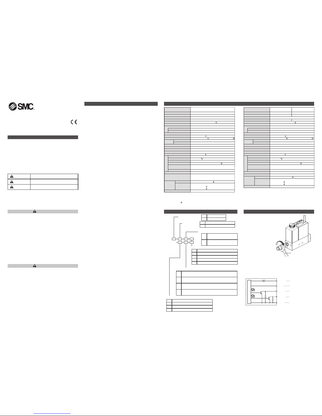
3. How to Order
• Do not disassemble, modify (including change of printed circuit
board) or repair the product.
An injury or product failure may result.
• Do not operate the product beyond the specification range.
Fire, malfunction or equipment damage may result. Use the product
only after confirming the specifications.
• Do not use the product in the presence of flammable, explosive
or corrosive gas.
Fire, explosion or corrosion may result. This product does not have an
explosion proof construction.
• When using the product as part of an interlocking system:
1) Provide a double interlocking system, for example a mechanical
system.
2) Check the product regularly to ensure proper operation.
• Before performing maintenance, be sure of the following:
1) Turn off the power supply.
2) Stop the air supply, exhaust the residual pressure and verify the
release of air from the system.
• Always perform a system check after maintenance.
Do not use the product if any error occurs.
Safety cannot be assured if caused by un-intentional malfunction.
• Provide grounding to ensure correct operation and to improve
noise resistance of the product.
This product should be individually grounded using a short cable.
•Follow the instructions given below when handling the product.
Failing to do so may result in product damage.
• Maintenance space should always be provided around the product.
• Do not remove labels from the product.
• Do not drop, hit or apply excessive shock to the product.
• Follow all specified tightening torques.
• Do not bend, apply tensile force, or apply force by placing heavy
loads, on the cables.
• Connect wires and cables correctly, and do not connect while the
power is ON.
• Do not route wires and cables together with power or high-voltage
cables.
• Check the insulation of wires and cables.
• Take proper measures against noise, such as noise filters, when the
product is incorporated in equipment or devices.
• Select the required protection (IP) rating according to the environment
of operation.
• Take sufficient shielding measures when the product is to be used in
the following conditions:
(1) where noise due to static electricity is generated.
(2) where electro-magnetic field strength is high.
(3) where radioactivity is present.
(4) where power lines are located.
• Do not use the product in a place where electric surges are generated.
• Use suitable surge protection when a surge generating load such as a
solenoid valve are to be directly driven.
• Prevent any foreign matter from entering this product.
• Do not expose the product to vibration or impact.
• Use the product within the specified ambient temperature range.
• Do not expose the product to any heat radiation.
• Do not clean the product with chemicals such as benzene or thinners.
F
ollow the instructions given below when handling your digital pressure
s
witch. Otherwise, the switch may be damaged or may fail, thereby
resulting in malfunction.
• Do not pull the lead wire with force nor lift the switch by holding the lead
wire. (Tensile strength: less than 49N.)
• Connect the terminal FG to ground when using a switching regulator
obtained on the commercial market.
• Insert a noise filter (line noise filter and ferrite core or other elements)
between the switching regulator and this digital pressure switch when analogue output is used.
• Do not use with corrosive or flammable gas or liquid.
• Do not press the setting buttons with a sharp pointed object.
• Do not rub the LCD indicator during operation (the display may change due
to static electricity.)
•
When performing piping, tighten the pipe by using a spanner on the hexagon
section of the attachment of the
digital pressure switch
(Do not apply force on
the switch body).
• Do not use this digital pressure switch in areas that are exposed to water,
oil or chemicals (open-type specification).
When the 0X or 0XY type (with filter) is used
• If the filter element (ZX1-FE) is clogged, stopoperation and replace the element.
ISE3
ZSE3
Piping specifications
Piping specifications
Wiring specifications
Input specifications
Output specifications
Pressure setting range
For positive
pressure
For vacuum
2. Specifications
Note 1) When vacuum is used, there is no influence on the switch even if 0.5 MPa of pressure is supplied
instantaneously.
Note 2) Only for the pressure switch with analogue output selected.
Note 3) In case of ZSE3- -23 or 24, failure predictive output: Red.
Environmental
V
acuum
Z
SE3
0
to -101 kPa
1
kPa
Air, non-corrosive gas
2
00 kPa (Note 1)
1
2 to 24 Vdc (Ripple 10 % or less)
2
5 mA or less
NPN open collector output
8
0 mA
3
0 Vdc
5
ms.
1 %F.S. or less
Voltage output: 1 to 5 V 5%, Output impedance: Approx. 1 k
V
ariable (0 digits or more)
F
ixed ( 3 digits)
3 1/2 digits LCD (character height 5 mm).
L
it when ON (OUT1: Green OUT2: Red)
D
etection of overcurrent, overpressure, data error, and pressure during 0 clear
I
ndicator: Red LED flashes. Error code displayed on LCD.
3 %F.S. or less
I
P40
0 to 60 (No condensation or freezing)
Between external terminal and case: 1000 Vac 50/60 Hz for 1 min.
B
etween external terminal and case: 2 M (by 500 Vdc M)
1
0 to 500 Hz 2 hours each in X, Y, and Z directions, at 10 to 500 Hz
with amplitude of 1.5 mm or acceleration 98m/s
2
, whichever smaller.
980m/s2, 3 times each in X, Y, and Z directions
C
E marked
Heat resistant vinyl wire 1.55 0.31 mm24-wire
O
il resistant vinyl heavy-duty cable
-
21,-23: 3.5 0.14 mm
2
4
-core
-22,-24: 3.5 0.15 mm
2
5-core
40 g (including lead wire 0.6 m)
Rc1/8, M5 x 0.8, NPT F1/8, M5 x 0.8,
M
5 x 0.8 with suction filter,
M
6 x 1 (made to order)
R
ated Pressure Range
M
inimum Setting Unit
F
luid
Maximum Operating Pressure
P
ower Supply Voltage
C
urrent Consumption
S
witch Output
M
odel
R
esponse Time
R
epeatability
Analogue Output (Note 2)
Hysteresis
(
Note 4)
Display Method
I
ndicator Light (Note 3)
S
elf-diagnosis Function
Error Indication
Temperature Characteristic
Standard
P
ort Size
L
ead Wire
M
aximum Load Current
M
aximum Applied Voltage
Hysteresis Mode
W
indow Comparator Mode
Connector type
G
rommet type
W
eight
Enclosure
A
mbient Temperature Range
W
ithstand Voltage
Insulation Resistance
V
ibration Proof
Impact Proof
Note 4)
Window Comparator Mode
: Since the hysteresis is 3 digits, P1 should be separated from P2 by
7 digits or more. 1 digit is the minimum setting unit (See the table
above).
R
ated Pressure Range
M
inimum Setting Unit
Fluid
Maximum Operating Pressure
P
ower Supply Voltage
C
urrent Consumption
Switch Output
M
odel
1
2 to 24 Vdc (Ripple 10 % or less)
25 mA or less
N
PN open collector output
8
0 mA
3
0 Vdc
5
ms.
1 %F.S. or less
V
oltage output: 1 to 5 V 5 %, Output impedance: Approx. 1 k
Variable (0 digits or more)
F
ixed ( 3 digits)
3
1/2 digits LCD (character height 5 mm).
Lit when ON (OUT1: Green OUT2: Red)
Detection of overcurrent, overpressure, data error, and pressure during 0 clear
I
ndicator: Red LED flashes. Error code displayed on LCD.
3 %F.S. or less
I
P40
0 to 60 (No condensation or freezing)
Between external terminal and case: 1000 Vac 50/60 Hz for 1 min.
B
etween external terminal and case: 2 M (by 500 Vdc M)
Air, non-corrosive gas
P
ositive Pressure 100kPa
I
SE3L
0
to 98 kPa
1
kPa
P
ositive Pressure 1MPa
I
SE3
0 to 0.98 MPa
0
.01 MPa
2
00 kPa (Note 1)
1
MPa
10 to 500 Hz 2 hours each in X, Y, and Z directions, at 10 to 500 Hz
w
ith amplitude of 1.5 mm or acceleration 98m/s
2
,
whichever smaller.
9
80m/s
2
,
3 times each in X, Y, and Z directions
CE marked
Rc1/8, M5 x 0.8, NPTF 1/8, M5 x 0.8
Heat resistant vinyl wire 1.55 0.31 mm24-wire
Oil resistant vinyl heavy-duty cable
-21: 3.5 0.14 mm
2
4-core
-22: 3.5 0.15 mm25-core
4
0 g (including lead wire 0.6 m)
Response Time
R
epeatability
A
nalogue Output (Note 2)
H
ysteresis
(Note 4)
D
isplay Method
Indicator Light (Note 3)
S
elf-diagnosis Function
E
rror Indication
Temperature Characteristic
Standard
Port Size
Lead Wire
M
aximum Load Current
M
aximum Applied Voltage
Hysteresis Mode
Window Comparator Mode
Connector type
G
rommet type
W
eight
Enclosure
Ambient Temperature Range
W
ithstand Voltage
I
nsulation Resistance
Vibration Proof
I
mpact Proof
Environmental
4. Installation
Piping connection
• Connect the digital pressure
switch to the piping with a
hexagon socket head plug and
a fitting.
• The tightening torque for piping
port must be 8.8N•m or less.
Spanner
LED Green
LED
Red
Main circuit
Power supply terminal (+)
Tr1 D1
Tr2 D2
DC (+)
Brown [+]
OUT3
Gray
OUT1
Black [1]
OUT2
White [2]
DC(
-
)
Blue [
-
]
Analog output
Output 1
Output 2
Power supply terminal (-)
Wiring connection
• Be sure to turn off the power supply before performing connection
work.
• Incorrect wiring will lead to digital pressure switch breakdown, failure
or malfunction. Be sure to confirm the wire colour and terminal number
before wiring.
Note) The symbol shown in [ ] means the pin assignment of connec-
tor connection type.
NIL 0 to 0.98 MPa
L 0 to 98 kPa
01
Single-installation type Rc 1/8
T1
Single-installation type NPTF 1/8
Not e) M5 x 0 .8 fem ale th read i s pr ovi ded on th e i nter nal s ide of th e pi pin g.
21
NPN open collector 2 outputs
Without analogue output
22
NPN open collector 2 outputs
With analogue output (1 to 5V)
NIL Grommet type lead wire (length: 0.6 m)
L Grommet type lead wire (length: 3 m)
C Connector type lead wire (Length: 0.6 m)
CL Connector type lead wire (length: 3 m)
CN Without connector
Note) Analogue output is available only for grommet type.
21
NPN open collector 2 outputs
Without analogue output
22
NPN open collector 2 outputs
With analogue output (1 to 5V)
23
NPN open collector 1 output and failure predictive output
Without analogue output
24
NPN open collector 1 output and failure predictive output
With analogue output (1 to 5V)
01 Single-installation type Rc 1/8
T1 Single-installation type NPTF 1/8
0X With suction filter M5 x 0.8
0XY With suction filter M6 x 1(made-to-order)
Note)An M5x0.8femalethread isprovidedon theinternalsideofthesingle-installationtypepiping.
Z
/ISE3-TFK26GB-A
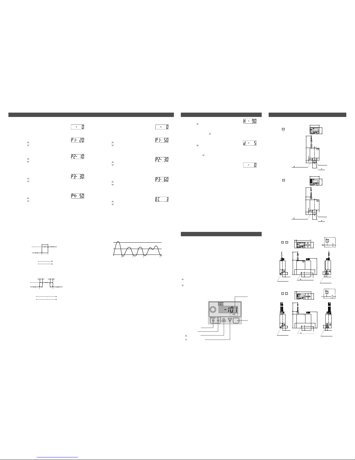
5. Functions Setting
1. Set value input mode
Press the "SET" button to display "P1-20 (*1)".
The output OUT1 (1) set value input mode is selected.
(*1: If the set value of P1 is -20).
2. OUT1 (1) set value input
Pressing the button increases the set value.
Pressing the button decreases the set value.
3
. Press the "SET" button to save the set value and select OUT1 (2)
set value input mode. The set value of P2 is displayed.
4. OUT1 (2) set value input
Pressing the button increases the set value.
Pressing the button decreases the set value.
5. Press the "SET" button to save the set value and select OUT2 (1)
set value input mode.
The set value of P3 is displayed.
6. Output OUT2 (1) set value input
Pressing the button increases the set value.
Pressing the button decreases the set value.
7. Press the "SET" button to save the set value and select OUT2 (2)
set value input mode.
The set value of P4 is displayed.
8. Output OUT2 (2) set value input
Pressing the button increases the set value.
Pressing the button decreases the set value.
9. Press the “SET” button to save the set value and exit this mode.
2-output Type
Note) P1: Set value for OUT1 (1) P2: Set value for OUT1 (2)
P3: Set value for OUT2 (1) P4: Set value for OUT2 (2)
Note)
• Hysteresis mode (same as for positive pressure use)
When the value of hysteresis is set to 2 digits or less, the switching
output might chatter due to fluctuation of the input pressure around
its set point.
• Window comparator mode (same as for positive pressure use)
Since the hysteresis will be 3digits, separate P1 from P2 (in case of
2-output type, same as for P3 and P4) by 7 digits or more.
* 1 digit is the minimum setting unit.
Output Method
Hysteresis mode (P1 P2, P3 P4)
Window comparator mode (P1<P2,P3<P4)
P1
(P3)
P2
(P4)
OFF
ON
Hysteresis (variable)
Pressure low Pressure high
Vacuum low
Vacuum high
P1
(P3)
Hysteresis (fixed)
OFF
ON
P2
(P4)
Hysteresis (fixed)
(Hysteresis = 3 digits fixed)
Pressure low Pressure high
Vacuum low
Vacuum high
1
. Set value input mode
Press the "SET" button to display "P1-50(*1)".
The output OUT1 (1) set value input mode is selected.
(*1: If the set value of P1 is -50.)
2. OUT1 (1) set value input
Pressing the button increases the set value.
Pressing the button decreases the set value.
3. Press the "SET" button to save the set value and select the output
OUT1 (2) set value input mode.
The set value of P2 is displayed.
4. OUT1 (2) set value input
Pressing the button increases the set value.
Pressing the button decreases the set value.
5. Press the "SET" button to save the set value and select the failure
predictive pressure set value input mode.
The failure predictive set value is displayed.
6. Failure predictive pressure set value input
P
ressing the button increases the set value.
Pressing the button decreases the set value.
7. Press the "SET" button to save the set value and select the failure
predictive count set value input mode.
The failure predictive count set value is displayed.
8. Failure predictive count set value input
Pressing the button increases the set value.
Pressing the button decreases the set value.
9. Press the “SET” button to save the set value and exit this mode.
1-output Type With the Failure Predictive Function
Note) P1: Set value for OUT1 (1) P2: Set value for OUT1 (2)
P3: Set value for failure predictive pressure
P4: Set value for failure predictive count
The failure predictive detection counter is incremented when the
switch is turned on then is turned off, without the pressure (exceeding P1) not reaching the failure predictive pressure (P3).
The failure predictive detection output is energized when the set failure predictive counter (EC) is incremented consecutively. When the
switch is turned ON and the pressure (exceeding P1) exceeds the
failure predictive pressure (P3), the failure predictive counter is reset.
(This example shows a case in the hysteresis mode.)
Failure Predictive Function
Degree of vacuum
High
Low
P3
P1
P2
Set pressure
Set pressure
Failure predictive count: Normal Once Twice 3 times
8. Outline dimensions (mm)
Dimensions
30
20.5
01:R1/8
T
1:NPTF1/8
Lead wire length
60039
8.5
3.5
(3000)
1
3
M5 0.8
2- 3.5 mounting hole
10
3
0
20.5
Lead wire length
60040.5
8.5
3.5
(3000)
13
01:R1/8
T1:NPTF1/8
M
5 0.8
2- 3.5 mounting hole
G
rommet Type
Connector Type
SE3- - C
IZ0
1
T1
SE3- -
IZ01
T
1
Single-installation Type
7
PV
20.5
PV
50.6
Vacuum
supply
p
ort
Vacuum
supply
port
Vacuum pad
connection
p
ort
Air pressure circuit diagram
Lead wire length
60051.5
10 22.6
2- 3.5 mounting hole
(3000)
6.5
18
58
8
10.25
0X:M5 x 0.8
0XY:M6 x 1.0
Vacuum supply port
0X:M5 x 0.8
0XY:M6 x 1.0
Vacuum supply port
0X:M5 x 0.8
0XY:M6 x 1.0
Vacuum pad
connection port
0X:M5 x 0.8
0XY:M6 x 1.0
Vacuum pad
connection port
5.75
10.2
7
20.5
50.6
50
10
10 22.6
6.5
18
58
Vacuum pad
connection
port
Air pressure circuit diagram
5.75
10.2
10.25
8
Lead wire length
600
2- 3.5 mounting hole
(3000)
Grommet Type
Connector Type
ZSE3-0X -
ZSE3-0X - C
Peak Hold Mode
Pressing the (UP) button when pressure is displayed enables the upper limit peak value (value with a high degree
of vacuum) to be held. In this case, "H" is displayed on the LCD. To
reset holding, press the (UP) button again.
Bottom Hold Mode
Pressing the (DOWN) button when pressure is
displayed enables the lower limit peak value (value with low vacuum) to be held. In this case "d" is displayed on the LCD. To return
holding, press the (DOWN) button again.
Reset Function
Pressing the RESET button causes the following:
1) Measurement mode
• Zero adjustment
• Clearing the peak hold mode or bottom hold mode
• Clearing the failure predictive function internal counter
• Resetting the failure predictive output
2) Upon error occurrence
• The data set in the setting mode is retained as is and the state
when the power supply was turned on is restored (System reset
is triggered).
• In case of a data error, the setting mode is selected. When you
finish setting, the state when the power supply was turned on is
restored (System reset is triggered).
Note) In the set value input mode, the reset function does not work.
6. Other Functions
7. Names / Functions of Individual Parts
RESET button
SET button
(DOWN) button
(UP) button
LED
LCD
Main Unit
RESET button : Resets at error occurrence and for 0 clear of
the display.
SET button : Switches the setting mode and enters the set
value.
LCD : Displays pressure value, setting mode, and
error code.
LED : The green LED lights up when output OUT1
is ON. The red LED lights up when output
OUT2 is ON. When both OUT1 and OUT2 are
ON, both the green and red LEDs light up.
Upon error occurrence, the red LED flashes.
(UP) button : Switches to the peak display mode and
increases the ON/OFF set value.
(DOWN) button : Switches to the bottom display mode and
decreases the ON/OFF set value.
 Loading...