

SMC Networks ISE35 Operation Manual
Operation
When the pressure exceeds the set value,
the Pressure switch will turn ON. When the
pressure falls below the set value by the
amount of hysteresis or more, the
Pressure switch will turn OFF. As a default
setting, the Pressure switch is set to turn
ON when the pressure exceeds 0.35 MPa,
and turn OFF when it is below 0.34 MPa.
If this condition,
shown to the right, is
acceptable, then keep
t
hese settings.
<How to perform>
1. Press the button in the measurement mode to display set values.
2. Press the or button to change the set value.
The button is to increase and the button is to decrease.
Press the button once to increase by one digit, and press it continuously
to keep increasing the set value.
Press the button once to decrease by one digit, and press it continuously
to keep decreasing the set value.
3. Press the button to complete the setting.
Wiring
Connection
Connections should only be made with the power supply turned off.
Use separate routes for the Pressure switch wiring and any power or high
voltage wiring. Otherwise, malfunction may result due to noise.
Ensure that the FG terminal is connected to ground when using a
commercially available switch-mode power supply. When a switch-mode
power supply is connected to the product, switching noise will be
superimposed and the product specification can no longer be met. This can
b
e prevented by inserting a noise filter, such as a line noise filter and ferrite
core, between the switch-mode power supply and the product, or by using a
series power supply instead of the switch-mode power supply.
Connector
Connecting / Disconnecting
When mounting the connector, insert it straight into the socket, holding the
lever and connector body, and push the connector until the lever hooks into
the housing, and locks.
When removing the connector, press down the lever to release the hook
from the housing and pull the connector straight out.
Digital Pressure Switch
Operation Manual
ISE35
The Pressure switch operates within a set pressure range during window
comparator mode. Set P_L, P_L (switch lower limit) and P_H, P_H (switch upper
limit) with the setting procedure above.
Indication LED (green): Displays the switch condition.
3-digit LED:
Displays the current status of pressure, setting mode and error code.
Four display modes can be selected: display always in red or green,
or display changing from green to red, or red to green, according to
the output status.
button (UP): Selects the mode or increases the ON/OFF set value.
Press this button to change to the peak display mode.
button (DOWN): Selects the mode or decreases the ON/OFF set value.
Press this button to change to the bottom display mode.
button (SET): Press this button to change to another mode and to set a value.
3
-digit LED
button (UP)
button (DOWN)
button (SET)
Indication LED
ISE35-N-∗ ISE35-R-∗
button (DOWN)
button (UP)
b
utton (SET)
Pin
Body of switch
Lead wire (Brown)
Lever
Lead wire (Blue)
Connector
Rubber cover
Lead wire with connector
(with rubber cover)
(Model: ZS-32-A)
Measurement mode
The measurement mode
is the condition where the
pressure is detected and
displayed, and the
switch function is
operating.
This is the basic mode,
and the other modes
should be selected for
setting changes and other
function settings.
1 s 1 s
Switch ON
S
witch OFF
0.35
0.34
Time [s]
Pressure [MPa]
A
t normally open mode
or
Displays in turn
N
ormally open
N
ormally closed
(
Default)
Setting of special function
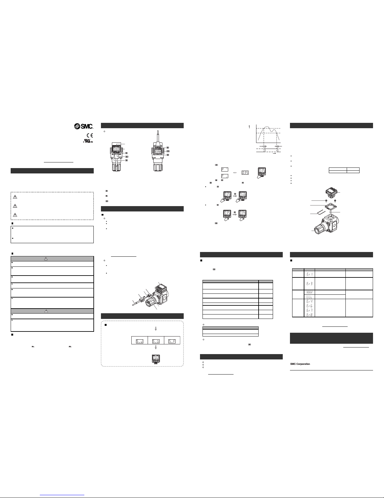
Mounting on to a regulator
C
ut the power supply to the Pressure switch when assembling. Also, turn the set
pressure of the regulator to zero.
Mount O-ring to the O-ring groove of the regulator. Attention should be taken not
to damage the O-ring.
Set the adapter with 2 set screws.
M
ount the main body of the Pressure switch.
Insert the lock pin to the adapter to the end firmly.
Supply pressure slowly, and ensure no air leaks.
The Pressure switch can be assembled rotated 180 degrees.
Set screw
Adapter
Lock pin
R
egulator
O-ring
Digital Pressure Switch
Modular AR/AW series
ARM10/11 series
0.6±0.05 Nm
0.32±0.03 Nm
Thank you for purchasing an SMC ISE35 Series Digital Pressure Switch.
Please read this manual carefully before operating the product and make sure you
understand its capabilities and limitations.
Please keep this manual handy for future reference.
To obtain more detailed information about operating this product, please
refer to the SMC website (URL http:// www.smcwor ld.com
) or co ntact SMC
directl y.
Safety Instructions
These safety instructions are intended to prevent hazardous situations and/or
equipment damage.
T
hese instructions indicate the level of potential hazard with the labels of
"Caution", "Warning" or "Danger". They are all important notes for safety and must
be followed in addition to International standards (ISO/IEC) and other safety
r
egulations.
CAUTION indicates a hazard with a low level of risk
which, if not avoided, could result in minor or
moderate injury.
Operator
T
his operation manual is intended for those who have knowledge of machinery
using pneumatic equipment, and have sufficient knowledge of assembly,
operation and maintenance of such equipment. Only those persons are
allowed to perform assembly, operation and maintenance.
Read and understand this operation manual carefully before assembling,
operating or providing maintenance to the product.
Caution:
Warning:
Danger:
WARNING indicates a hazard with a medium level of
risk which, if not avoided, could result in death or
serious injury.
DANGER indicates a hazard with a high level of risk
which, if not avoided, will result in death or serious
injury.
Safety Instructions
Do not disassemble, modify (including changing the printed circuit board) or repair.
An injury or failure can result.
Do not operate in an atmosphere containing flammable or explosive gases.
Fire or an explosion can result.
This product is not designed to be explosion proof.
Do not use the product in a place where static electricity is a problem.
Otherwise it can cause failure or malfunction of the system.
NOTE
•The direct current power supply to be used should be UL approved as follows:
Circuit (of Class2) which is of maximum 30 Vrms (42.4 V peak), with UL1310
Class2 power supply unit or UL1585 Class2 transformer.
•The product is a approved product only if it has a mark on the body.
If using the product in an interlocking circuit:
•Provide a double interlocking system, for example a mechanical system
•Check the product regularly for proper operation
Otherwise malfunction can result, causing an accident.
The following instructions must be followed during maintenance:
•Turn off the power supply
•Stop the air supply, exhaust the residual pressure and verify that the air is released before performing
maintenance work
Otherwise an injury can result.
After maintenance is complete, perform appropriate functional inspections and leak tests.
Stop operation if the equipment does not function properly or there is a leakage of fluid.
When leakage occurs from parts other than the piping, the product might be faulty.
Disconnect the power supply and stop the fluid supply.
Do not apply fluid under leaking conditions.
Safety cannot be assured in the case of unexpected malfunction.
Do not touch the terminals and connectors while the power is on.
Otherwise electric shock, malfunction or damage to the product can result.
D
o not operate the product outside of the specifications.
Do not use for flammable or harmful fluids.
Fire, malfunction, or damage to the product can result.
Verify the specifications before use.
Warning
Summary of Product parts
Names of individual parts
Mounting and Installation
Pressure Setting
Function Setting
Default setting
At the time of shipment, the following settings are provided.
If the setting is acceptable, keep it for use.
When the button is pressed for 2 seconds or longer, the parameter settings
can be changed.
Refer to the SMC website (URL http://www.smcworld.com) for more detailed
information about setting changes, or contact SMC.
Setting item
Switch output
Selects whether or not the Pressure switch output is made available.
If the switch output is unnecessary, it is available just like a pressure gauge.
Display colour
Selects the display colour.
Response time
Sets a response time to prevent chattering in the output.
Operation mode
Selects the mode to operate the Pressure switch.
Default setting
ON
ON: Green
OFF: Red
1 s
Hysteresis mode
Hysteresis 0.01 MPa (1 psi)
Output type
Sets the method to generate the switch output.
Power saving mode
Selects the power saving mode.
Security code input
Selects the security code option for key lock.
Display reverse mode
Selects the reverse display mode
Normally open
OFF
OFF
The value in ( ) is for the indication unit "P".
Indication unit (available with unit conversion function)
Setting item
Other Settings
Peak / Bottom hold display
Zero clear
Key lock
To set each of these functions, refer to the SMC website
(URL http://www.smcworld.com
) for more detailed information, or contact SMC.
Maintenance
How to reset the product after a power cut or forcible de-energizing
The setting of the product will be retained as it was before a power cut or
de-energizing.
The output condition is also basically recovered to that before a power cut or
de-energizing, but may change depending on the operating environment.
Therefore, check the safety of the whole installation before operating the product. If
the installation is using accurate control, wait until the product has warmed up
(approximately 20 to 30 minutes).
Troubleshooting
Note: Specifications are subject to change without prior notice and any obligation on the part of the manufacturer.
© 2011 SMC Corporation All Rights Reserved
Akihabara UDX 15F, 4-14-1, Sotokanda, Chiyoda-ku, Tokyo 101-0021, JAPAN
Phone: +81 3-5207-8249 Fax: +81 3-5298-5362
URL http://www.smcworld.com
The switch output load current is more
than 80 mA.
Turn the power off and remove the
c
ause of the over current. Then turn
the power on.
Over current
error
Error name Error display Error type Troubleshooting method
Residual
pressure
error
Pressurizing
error
System error
During the zero clear operation, pressure
a
bove ±10%F.S. has been applied. After
3 s, the mode will reset to the
measurement mode. The zero clear
range can vary ±1 digit with individual
product differences.
Perform zero clear operation again
after restoring the applied pressure
to an atmospheric pressure
condition.
Pressure has exceeded the upper limit of
the set pressure range.
Displayed in the case of an internal data
error.
Reset applied pressure to a level
within the set pressure range.
Turn the power off and turn it on
again.
If resetting fails, an investigation by
SMC Corporation will be required.
Pressure has exceeded the lower limit of
the set pressure range.
Error indication
This function is to display error location and content when a problem or an error
occurs.
If the error can not be reset after the above measures are taken, then please
contact SMC.
Caution
Recommended tightening torque:
Indication unit: M Indication unit: P Indication unit: Nil
Measurement starts and the
current pressure is displayed.
The symbol to show the indication
unit appears for approx. 1 s.
The power is supplied.
NOTE
When the default setting is changed, since the different setting item appears
in order depending on how many times the button is pressed, confirm the
item which needs to be set appears correctly and prevent undesired setting.
Specifications
Outline with Dimensions (in mm)
Refer to the product catalogue or SMC website (URL http://www.smcworld.com) for
more information about the product specifications and outline dimensions.
Refer to the SMC website (URL http://www.smcworld.com
) for more information
about troubleshooting.
Refer to the product catalogue or SMC website
(URL http://www.smcworld.com
) for more information about wiring.
 Loading...