

SMC Networks ZSE30, ISE30 Series Series Manual
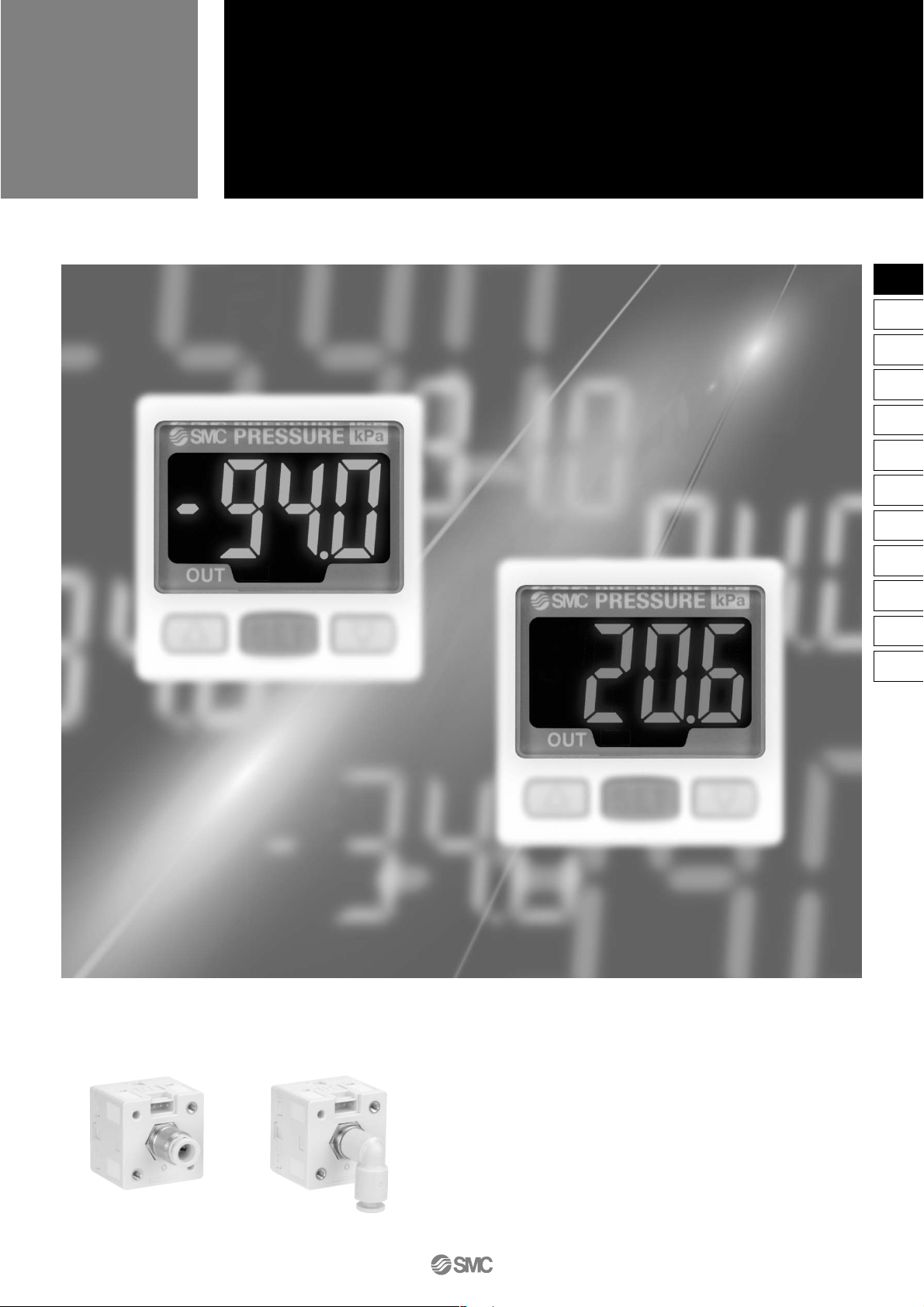
Straight type Elbow type
High Precision,
2-color Display Digital Pressure Switch
Series
ZSE30/ISE30
With One-touch fittings
are newly introduced.
16-2-1
ZSE
ISE
PSE
Z
I
SE3
PS
Z
I
SE
1
2
ZSP
ISA2
IS
ZSM
PF2
IF
Data
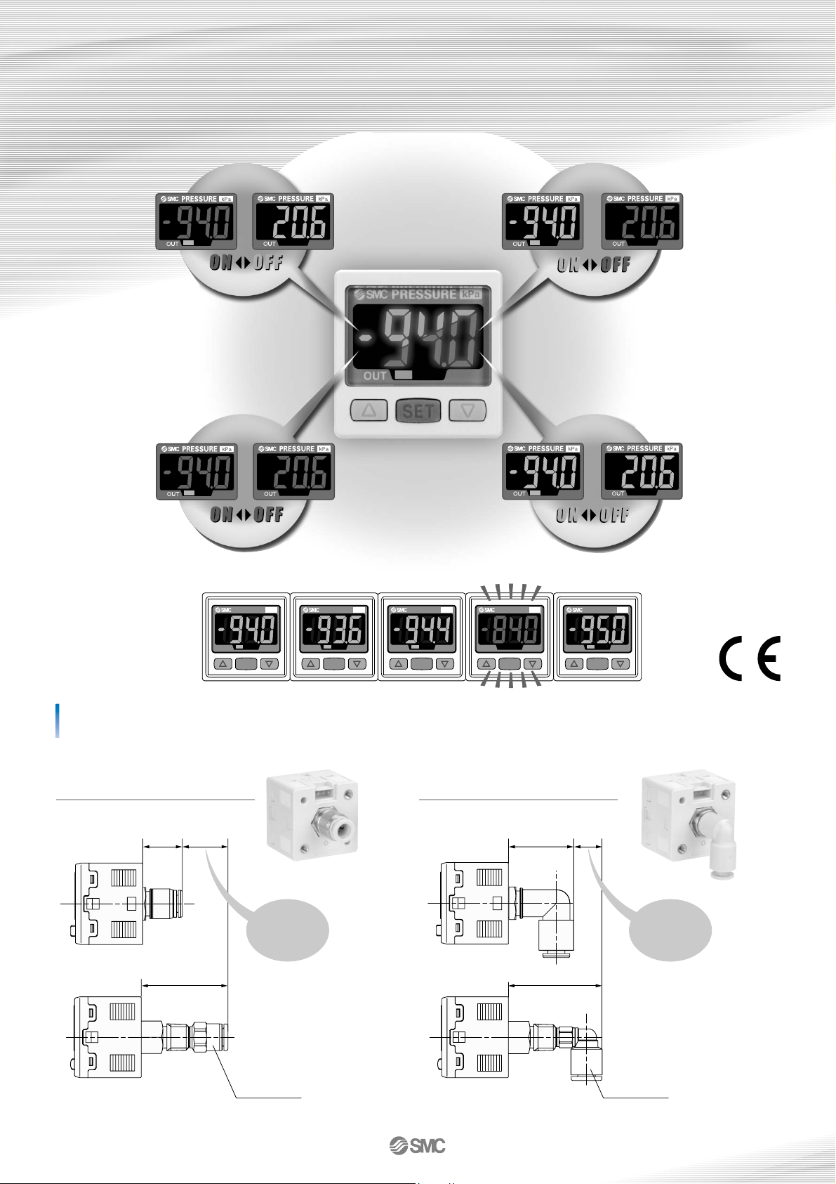
Abnormal conditions can be detected at a glance!
SET
kPa
PRESSURE
OUT
SET
kPa
PRESSURE
OUT
SET
kPa
PRESSURE
OUT
SET
kPa
PRESSURE
OUT
SET
kPa
PRESSURE
OUT
With One-touch fitting (ø4, ø6, ø5/32", ø1/4")
Reduced dimensions in piping direction
2-color digital display allows you to choose
the setting according to your application requirements.
4 different display settings are available.
17.8 mm reduction
∗
Straight type
12.4 mm reduction
∗
Elbow type
∗ Comparison when One-touch fittings (KQ2H06-M5 / KQ2L06-M5) are connected to the piping ports (M5 x 0.8)
14.4
32.2
22.4
34.8
12.4 mm17.8 mm
KQ2H06-M5 KQ2L06-M5
∗ This photo shows 2
display colors
simultaneously for
product presentation
purposes. In actual
application, only one
color is displayed at a
time.
16-2-2
Plug-type
connectors take the
burden out of
wiring work and
maintenance.
Raised rubber
button controls are
clearly set apart,
simple to operate,
soft to the touch.
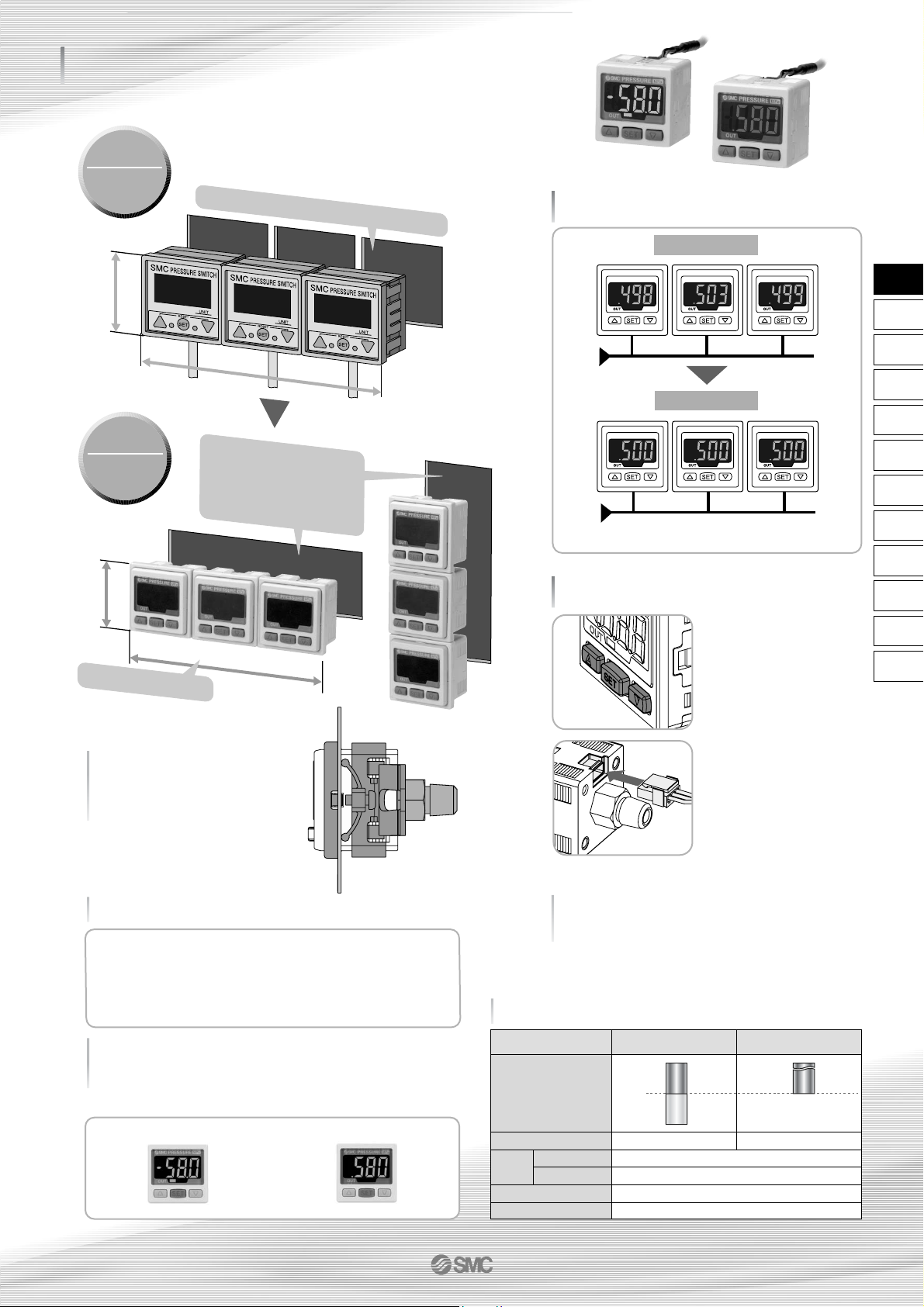
This function allows uniformity in the numbers displayed.
Space-saving improvement
Economical use of space
High-precision
resolution: 1/1000
Switches for vacuum and positive
pressure can be easily distinguished.
The different display panel frame colors easily tell them apart.
Variations
Applicable
panel thickness is
up to 6 mm.
(Panel mounting)
With analog output
Display calibration
Old Model
New Model
Old Model
ZSE4E
ISE4E
103.5
34.5
Compact profile
Just one panel opening is
required for stackable
displays, which can be
mounted either horizontally
or vertically.
126
40
More user-friendly controls
Each display required its own panel opening.
New Model
ZSE30
ISE30
Vacuum/Low pressure (ZSE30)
Positive pressure (ISE30)
Blue
Gray
In addition to the conventional voltage output type (1 to 5 V)
Current output type (4 to 20 mA)
is now available.
• Convenient when longer wiring is required
• Excellent noise resistance
Rated pressure
range
Setting/Display resolution
0.2 kPa
0.001 MPa
Output
Switch output
Analog output
NPN/PNP open collector (1 output)
Voltage output: 1 to 5 V; Current output: 4 to 20 mA
45 mA or less (70 mA or less for current output)
Panel mount/Bracket
Current consumption
Option
Vacuum/Low pressure
ZSE30
Positive pressure
ISE30
100 kPa
–100 kPa
0
1 MPa
0
16-2-3
ZSE
ISE
PSE
Z
I
SE3
PS
Z
I
SE
1
2
ZSP
ISA2
IS
ZSM
PF2
IF
Data
High Precision,
2-color Display Digital Pressure Switch
Series
ZSE30/ISE30
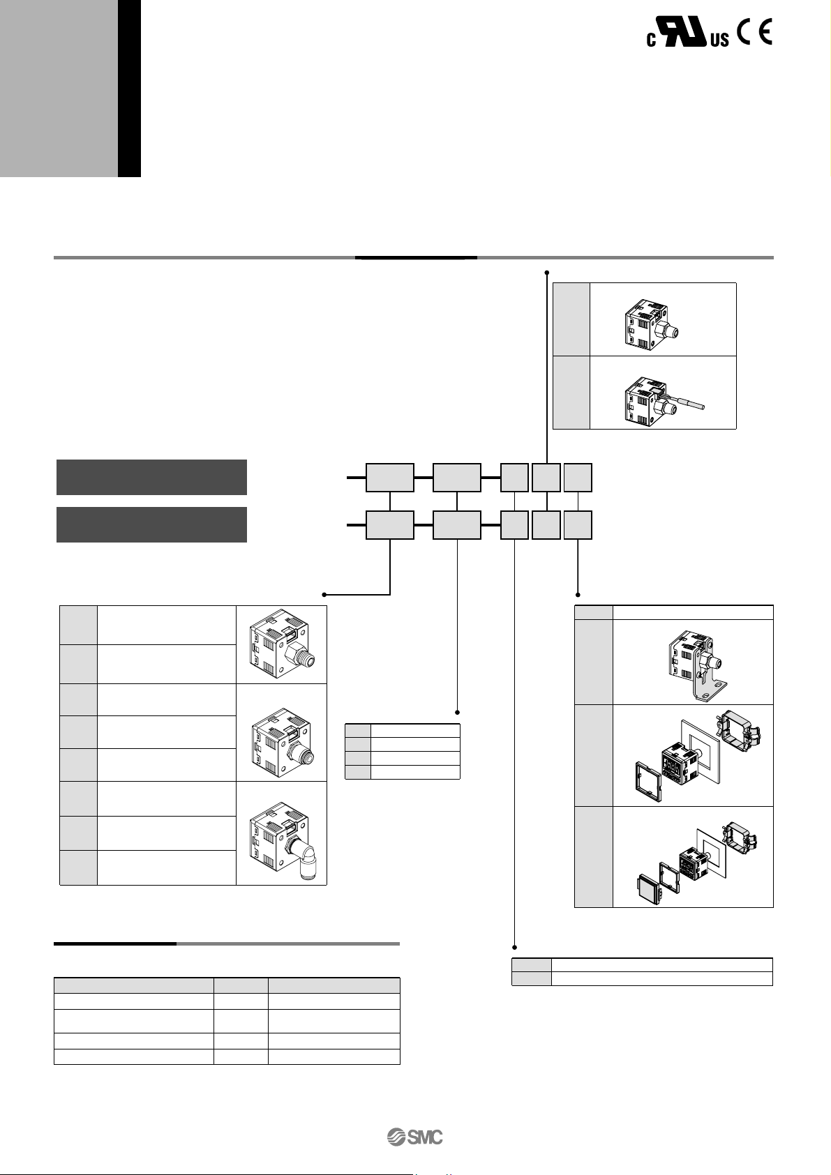
How to Order
Option Part No.
When optional parts are required separately, use the following part
numbers to place an order.
Option Part no.
ZS-27-A
ZS-27-B
ZS-27-C
ZS-27-D
Note
Lead wire length: 2 m
With mounting screws
(M3 x 5L: 2 pcs.)
With M3 x 8L (2 pcs.)
With M3 x 8L (2 pcs.)
Lead wire with connector
Bracket
Panel mount adapter
Panel mount adater + Front protective cover
ZSE30 01
ISE30 01
25 M
25 M
For vacuum/low pressure
For positive pressure
Unit specifications
Nil
M
With unit switching function
Fixed SI unit (International System of Units)
Note)
Note) Fixed unit:
For vacuum/Low pressure: kPA
For positive pressure: MPa
NPN output
PNP output
1 to 5 V output
4 to 20 mA output
Output specifications
25
65
26
28
Option 2
Nil
A
None
Bracket
B
D
Panel mount
Panel mount adapter +
Front protective
cover
Without lead wire
Lead wire with connector
(Lead wire length: 2 m)
Option 1
Nil
L
R 1/8
(With M5 female thread)
NPT 1/8
(With M5 female thread)
ø4 One-touch fitting
ø5/32" One-touch fiting
ø6 One-touch fitting
ø1/4" One-touch fitting
ø4 One-touch fitting
ø5/32" One-touch fitting
ø6 One-touch fitting
ø1/4" One-touch fitting
01
T1
C4H
C6H
N7H
C4L
C6L
N7L
Piping specifications
Elbow type
Straight type
®
16-2-4
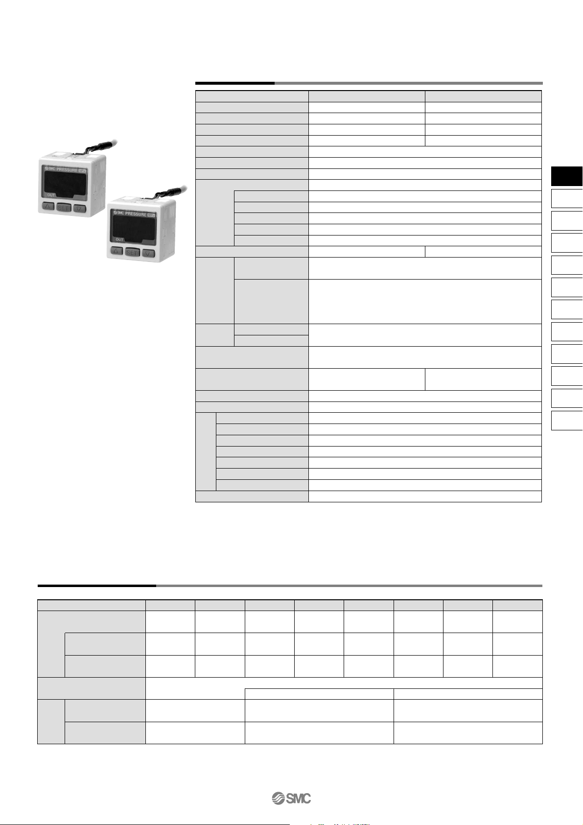
Specifications
Rated pressure range
Regulating pressure range
Proof pressure
Min. regulating unit
Fluid
Power supply voltage
Current consumption
Switch output
Repeatability
Analog
output
Hysteresis
Display
Display accuracy
Indicator light
Temperature characteristics
Standard
Note 1)
Max. load current
Max. applied voltage
Residual voltage
Response time
Short circuit protection
Voltage output
Note 2)
Current output
Note 3)
Hysteresis mode
Window comparator mode
ZSE30 (Vacuum/Low pressure)
–100.0 to 100.0 kPa
–101.0 to 101.0 kPa
500 kPa
0.2 kPa
±0.2% F.S. ±2 digit or less
±2% F.S. ±2 digit
(at 25°C ambient temperature)
ISE30 (Positive pressure)
0.000 to 1.000 MPa
–0.100 to 1.000 MPa
1.5 MPa
0.001 MPa
±0.2% F.S. ±1 digit or less
±2% F.S. ±1 digit
(at 25°C ambient temperature)
Air, Inert gas, Non-flammable gas
12 to 24 VDC, Ripple (p-p) 10% or less (With power supply polarity protection)
45 mA or less (at no load)
NPN or PNP open collector output: 1 output
80 mA
30 V (With NPN output)
1 V or less (With load current of 80 mA)
2.5 ms or less (Response time selections with anti-chattering function: 20, 160, 640, 1280 ms)
Ye s
Output voltage: 1 to 5 V ±2.5% F.S. or less (With rated pressure range)
Linearity: ±1% F.S. or less, Output impedance: Approx. 1 kΩ
Output current: 4 to 20 mA ±2.5% F.S. or less (With rated pressure range)
Linearity: ±1% F.S. or less
Maximum load impedance: 300 Ω with power supply voltage of 12 V;
600 Ω with power supply voltage of 24 V
Minimum load impedance: 50 Ω
Adjustable (can be set from 0)
3 1/2 digit, 7-segment indicator, 2-color display (Red and green)
Sampling cycle: 5 times/s
Light up when output is ON (Green)
±2% F.S. or less (based on 25°C)
IP40
Operating: 0 to 50°C, Stored: –10 to 60°C (No freezing or condensation)
Operating and stored: 35 to 85% RH (No condensation)
1000 VAC for 1 min. between live parts and enclosure
50 MΩ or more between live parts and enclosure (at 500 VDC)
10 to 150 Hz, 1.5 mm or 20 m/s2 amplitude in X, Y, Z directions for 2 hours each
100 m/s2 in X, Y, Z directions 3 times each
Compliant with CE Marking and UL (CSA) standards
Piping Specifications
Par t
Por t
size
Wetted part material
Weight
One-touch fitting
Straight type
One-touch fitting
Elbow type
With lead wire
with connector (2 m)
Without lead wire
with connector
01
R 1/8
M5 x 0.8
—
—
81 g
43 g
T1
NPT 1/8
M5 x 0.8
—
—
C4H
—
ø4 mm
ø5/32 inch
—
C6H
—
ø6 mm
—
O-ring: NBR
76 g
38 g
N7H
—
ø1/4 inch
—
Sensor pressure receiving area: Silicon, Piping port: C3602 (Electroless nickel plated), O-ring: HNBR
C4L
—
—
ø4 mm
ø5/32 inch
C6L
—
—
ø6 mm
O-ring: NBR, fitting: PBT
78 g
40 g
N7L
—
—
ø1/4 inch
Note 1) When switch output is selected, analog output is not available.
Note 2) When voltage output is selected, a simultaneous selection of switch output and current output is
not available.
Note 3) When current output is selected, a simultaneous selection of switch output and voltage output is
not available.
Enclosure
Operating temperature range
Operating humidity range
Withstand voltage
Insulation resistance
Vibration resistance
Impact resistance
Environmental
resistance
16-2-5
ZSE
ISE
PSE
Z
I
SE3
PS
Z
I
SE
1
2
ZSP
ISA2
IS
ZSM
PF2
IF
Data
Series ZSE30/ISE30
High Precision,
2-color Display Digital Pressure Switch
(Standard: Factory setting)
(Reversed)
(Standard: Factory setting)
(Reversed)
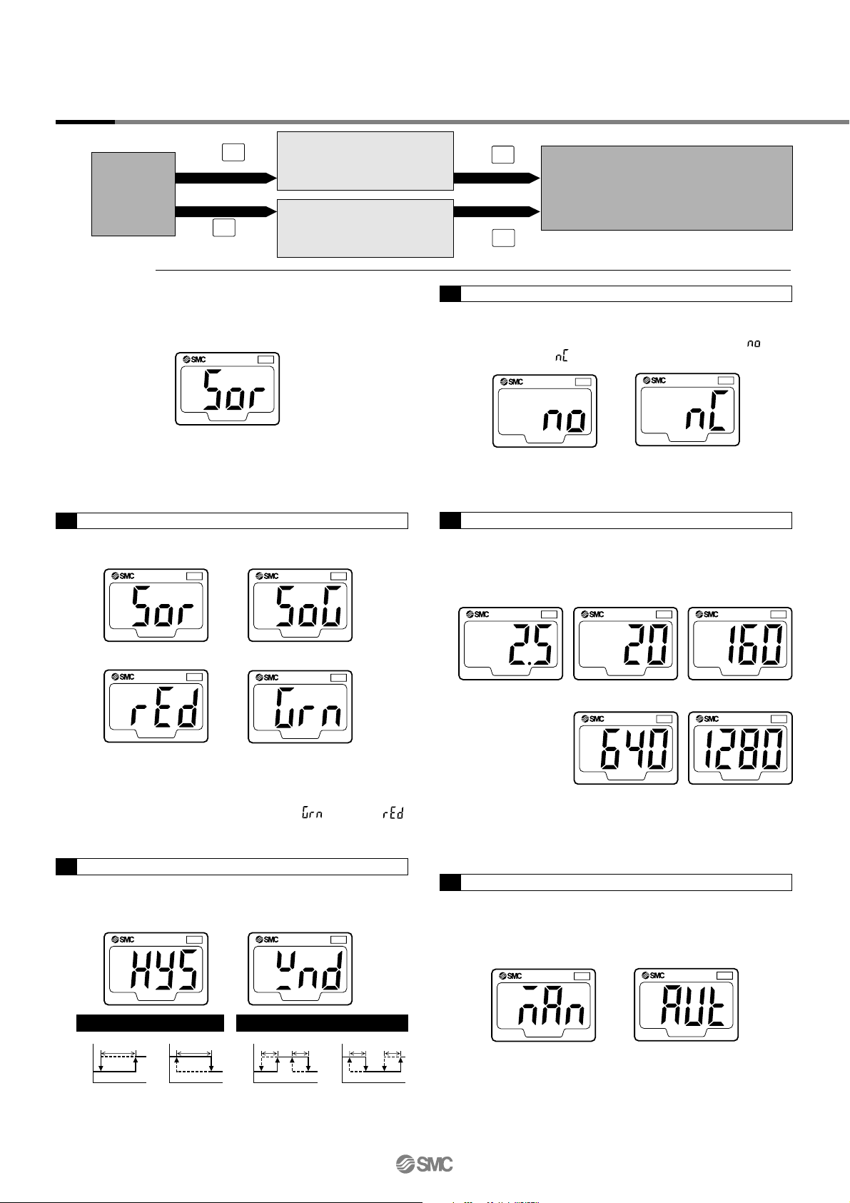
Setting
Initial Setting
Measuring
mode
Initial setting
Pressure setting
Measuring mode
Initial setting mode
Press and hold the SET button for 2 seconds or longer.
Display monitor will be per Figure A below, and the switch
will now be in the display color setting mode.
If the unit specification indicated at the time of ordering is “M”,
the fixed SI unit will be used. If it is Nil, refer to “Unit Switching
Function” on page 16-2-8.
The switch output response time can be set arbitrarily.
Chattering can be prevented with a response time setting.
While the current response time is displayed, press the UP
or DOWN button to select a new response time.
This function stores the measuring pressure that is set
during the auto preset mode as a basic value.
While the current setting is displayed, press the UP or
DOWN button to select it as an auto preset setting.
Press the SET button to set the response time and proceed
to the auto preset setting.
If the operating mode is the window comparator mode, press
the SET button to return to the measuring mode.
The type of switch output can be set arbitrarily.
While the current output type is displayed, press the
DOWN button to switch between normally open and
normally closed .
PRESSURE
OUT
Figure A
PRESSURE
OUT
ON: Red
This mode will let you select the switch operating mode.
While the current operating mode is displayed, press the
UP or DOWN button to select a newly desired operating
Select the color for LCD display.
Press the UP or DOWN button to choose a display color.
Press the SET button to set the color and proceed to the
operating mode setting.
If the analog output is set, press the UP or DOWN button
and select the desired display color from (Green) or
(Red). Press the SET button to exit this mode and return to
the measuring mode.
PRESSURE
OUT
PRESSURE
OUT
PRESSURE
OUT
ON: Green
ON/OFF: Red ON/OFF: Green
PRESSURE
OUT
PRESSURE
OUT
Hysteresis mode Window comparator mode
Normally open
Normally closed
PRESSURE
OUT
PRESSURE
OUT
PRESSURE
OUT
PRESSURE
OUT
PRESSURE
OUT
PRESSURE
OUT
PRESSURE
OUT
2.5 ms 20 ms 160 ms
640 ms 1280 ms
PRESSURE
OUT
PRESSURE
OUT
Manual Auto
Press the button.
ON
OFF
Hysteresis
(H)
P1
ON
OFF
n1
Hysteresis
(H)
ON
OFF
P2P1
Hysteresis
(H)
Hysteresis
(H)
ON
OFF
n2n1
Hysteresis
(H)
Hysteresis
(H)
Press the button.
Press the button.
Press the button
and hold for 2 sec. or longer.
Enter the set value of the
pressure to perform switch
output.
Set the output type, response
time, and display color
switching.
Detects and displays the pressure and
performs switch operations. Other functions
such as the value clear function can be set
according to the application purpose.
Press the SET button to set the output type and proceed to
the response time setting.
3. Output type setting
4. Response time setting
5. Auto preset setting
Press the SET button to set the auto preset and return to the
measuring mode.
1. Display color setting
2. Operating mode setting
Press the SET button to set the mode and proceed to the
output type setting.
SET
SET
SET
SET
16-2-6
Series ZSE30/ISE30
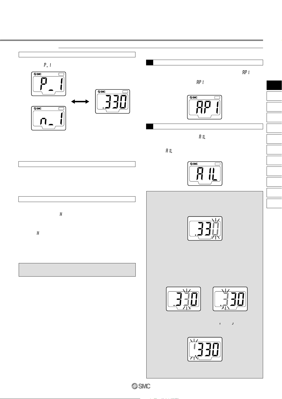
Pressure setting
Manual setting
Press the SET button in the measuring mode to display the
set value. and the current set value blink alternately.
Press the SET button to display the next set value. Press the
UP or DOWN button to change the value. (Refer to “How
to Set Value” on the lower right hand corner of this page.)
Hysteresis mode
In this mode, hysteresis (H) and the set value for hysteresis
are displayed alternately after setting P1. Press the SET
button to return to the normal measuring mode. Press the
UP or DOWN button to change the value.
(Refer to “How to Set Value” below right.)
Window comparator mode
In this mode, P2 and the current set value are displayed
alternately after setting P1. Press the SET button to display
the next set value ( : hysteresis). Press the UP or DOWN
button to change the value.
(Refer to “How to Set Value” at right.)
Next, and the set value for hysteresis will be displayed
alternately. Press the SET button to return to the normal
measuring mode. Press the UP or DOWN button to
change the value.
(Refer to “How to Set Value” at right.)
1. Auto preset preparation mode
While in the measuring mode, press the SET button to
activate the auto preset preparation mode, and will be
displayed. Proceed to prepare the devices to perform the
pressure setting. While is still displayed, press both the
UP and DOWN buttons simultaneously to return to the
measuring mode.
2. Auto preset setting
Press the SET button to activate the mode to execute auto
preset functions. When is displayed, start the system
operation and change the pressure. The set value will be
automatically detected and stored.
While is still displayed, press the SET button to complete
the setting and return to the normal measuring mode.
PRESSURE
OUT
Alternately
displayed
PRESSURE
OUT
Normally Open
Normally Closed
PRESSURE
OUT
PRESSURE
OUT
PRESSURE
OUT
1. Press the UP or DOWN button to change the set
value. The first digit blinks.
2. Press the UP or DOWN button to set the value
arbitrarily. (If there is no button operation for more than
10 seconds, the current value will be automatically set
and the function will return to the set value display
mode.)
3. With every push of the SET
button, the next (higher)
digit blinks.
When the left-most digit is zero, “ ” or “ ” will blink.
If the SET button is pressed while the left-most digit is
blinking, the right-most digit will now blink.
4. Press and hold the SET button for 1 second or longer
to return to the set value display mode.
How to Set Value
To enter a value such as the one for pressure setting:
1st digit
2nd digit 3rd digit
Auto preset setting
Pressure set value can be verified without holding or stopping
the switch output operation.
16-2-7
ZSE
ISE
PSE
Z
I
SE3
PS
Z
I
SE
1
2
ZSP
ISA2
IS
ZSM
PF2
IF
Data
Series ZSE30/ISE30
High Precision,
2-color Display Digital Pressure Switch
0
Applied pressure
+
: Factory setting display value
set prior to shipment
: Display calibration range
±5% R.D.
(±2.5% R.D.)
Displayed pressure value
Setting
Function setting
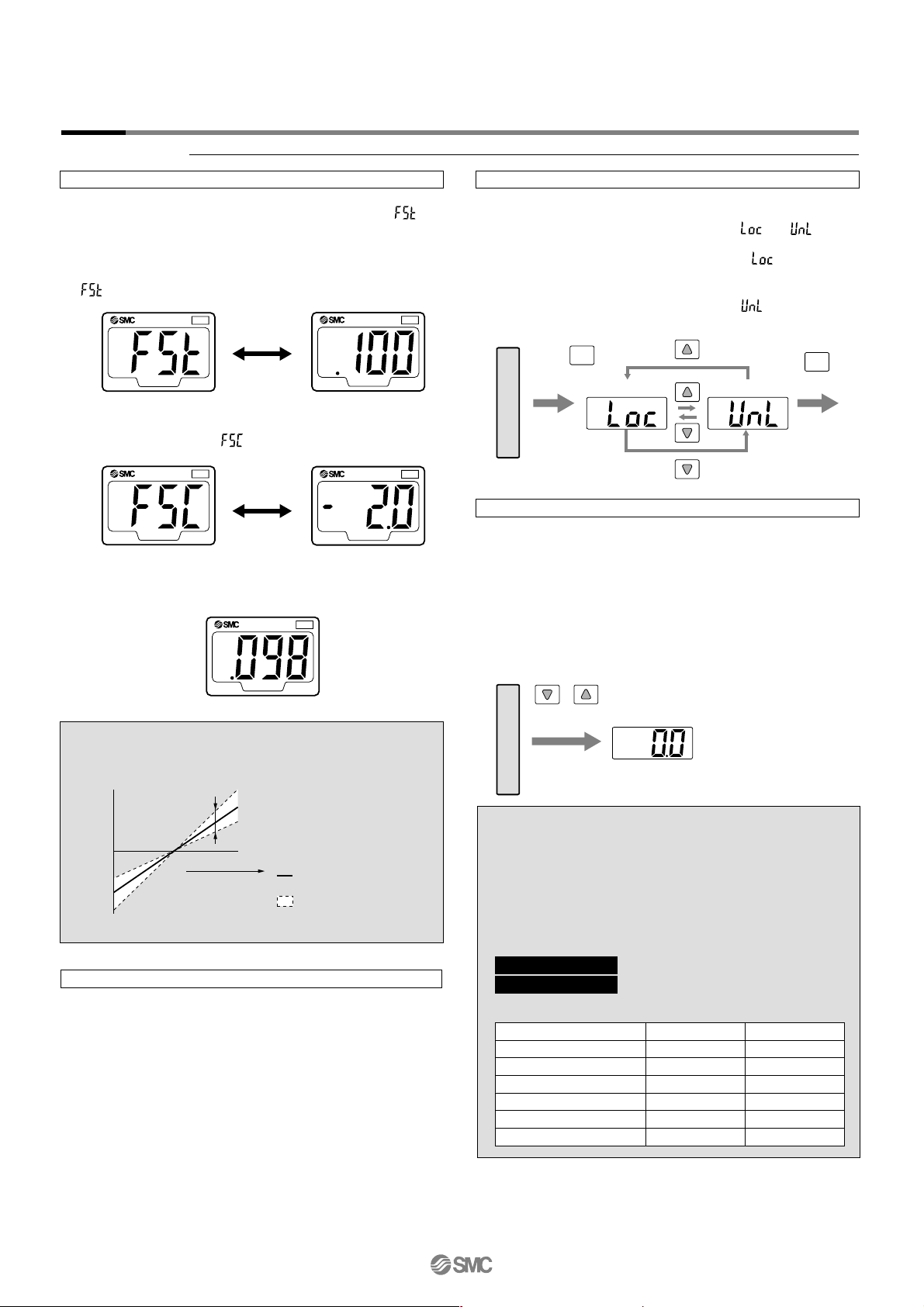
Display calibration
During measuring mode, press the SET and DOWN buttons
simultaneously and hold for 2 seconds or longer. and
current measured value will be displayed.
Press the UP or DOWN button to change the set value. If
there is no button operation for more than 2 seconds after
changing the set value, the display mode returns to displaying
and the current measured value.
Press the SET button to display the adjusted value (percent).
The adjusted value and will be alternately displayed.
Peak/Bottom hold function
This function constantly detects and updates the maximum
and minimum pressure values and allows to hold the display
value.
To use a peak hold function, press and hold the UP button
for 1 second or longer. The maximum pressure value is held
and blinks repeatedly. Press and hold the UP button again
for 1 second or longer to release this function and return to
the measuring mode.
To use a bottom hold function, press the DOWN button for 1
second or longer. The minimum pressure value is held and
blinks repeatedly. Press and hold DOWN button again for 1
second or longer to release this function and return to the
measuring mode.
Key lock function
This function prevents incorrect operations such as changing
the set value accidentally. Press the SET button and hold for 4
seconds or longer to display the current or setting.
Press the UP or DOWN button to select the setting and set
this function with the SET button. Use the mode to avoid
accidental button operation. To release a key lock function,
press the SET button and hold for 4 seconds or longer to
display the current setting, and select the mode.
Zero out (Zero ADJ) function
This function clears and resets the displayed value as long as
the measuring pressure is within ±70 digits of the atmospheric
pressure.
(Due to individual product differences, the setting range varies
±10% F.S.)
This function is effective in detecting pressure fluctuations that
exceed a certain amount without being affected by the supply
pressure. Press and hold the UP and DOWN buttons
simultaneously to reset the display. Release the buttons to
return to the measuring mode.
Press the SET button to return to the normal measuring mode.
Alternately
displayed
Alternately
displayed
PRESSURE
OUT
PRESSURE
OUT
PRESSURE
OUT
PRESSURE
OUT
PRESSURE
OUT
For vacuum/low pressure Pa⇔kgf/cm2⇔bar⇔psi⇔inchHg⇔mmHg
For positive pressure
MPa⇔kgf/cm2⇔bar⇔psi
Current measured value
Adjusted value
(Percent)
+
Lock
Selection of lock and unlock
Unlock
Press the button
and hold for 4 sec.
or longer
SET
SET
Displayed unit
Pa
kgf/cm
2
bar
psi
mmHg
inchHg
ISE30
0.001 MPa
0.01
0.01
0.2
—
—
ZSE30
0.2 kPa
0.002
0.002
0.05
2
0.2
Indication of Units
This function eliminates slight differences in the output values and
allows uniformity in the numbers displayed.
Displayed values of the pressure sensor can be calibrated to within
±5% for Series ISE and ±2.5% for Series ZSE.
Note) When the display calibration function is used, the regulating pressure
value may change ±1 digit.
Press and hold for
1 second or longer.
Measuring mode
Measuring mode
Measuring mode
When not selecting “M” for unit specification
Desired display unit can be selected.
Press the UP or DOWN button to switch the unit, and
the set value is automatically converted.
The conversion order is: PA⇔GF⇔bAr⇔PSi⇔inH⇔mmH
Press the SET button to set the unit and proceed to the
display color setting.
Unit Conversion Function
16-2-8
Series ZSE30/ISE30
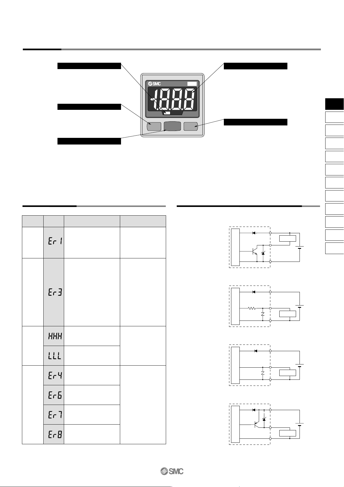
Error
description
overcurrent
error
Residual
pressure
error
Applied
pressure
error
System
error
LCD
display
Condition
Solution
Ta ke the following corrective solutions when errors occur.
Load current of switch
output is more than 80 mA.
Pressure is applied during the
zero out operation as follows:
When the switch for positive
pressure is used: ±0.071 MPa
or more.
When the switch positive
pressure is used:
±7.1 kPa or more.
After displaying for 3 seconds,
it will return to the measuring
mode. Due to the individual
product difference, the setting
range varies ±10% F.S.
Supply pressure exceeds
the maximum regulating
pressure.
Supply pressure is below
the minimum regulating
pressure.
Shut off the power
supply. After eliminating
the output factor that
caused the excess
current, turn the power
supply back on.
Bring the pressure
back to atmospheric
pressure and try
using the zero out
function.
Reduce/Increase
supply pressure to
within the regulating
pressure range.
Shut off the power
supply. Turn the
power supply back
on.
If the power should
not come back on,
please contact SMC
for an inspection.
SET
MPa
PRESSURE
OUT
Description
Error Correction
Example of Internal Circuit and Wiring
Indication light (Green)
LCD display
DOWN button
Displays the switch operation status.
UP button
SET button
-25
NPN open collector output
Maximum 30 V, 80 mA
Residual voltage:
1 V or less
-26
Analog output type
1 to 5 V (±2.5% F.S.)
Output impedance:
1 kΩ
-28
Analog output type
4 to 20 mA (±2.5% F.S.)
Maximum load impedance:
Power supply voltage 12 V: 300 Ω
Power supply voltage 24 V: 600 Ω
Minimum load impedance: 50 Ω
-65
PNP open collector
Maximum 80 mA
+
–
+
–
+
–
+
–
Load
Brown DC(+)
Black OUT
Blue DC(–)
Load
Brown DC(+)
Black OUT
(Analog output)
Blue DC(–)
Main circuit
Load
Brown DC(+)
Black OUT
(Analog output)
Blue DC(–)
Brown DC(+)
Black OUT
Blue DC(–)
Load
12
to
24 VDC
Displays the current pressure
condition, setting mode
conditions, selected display unit,
and error codes. A display color
type can be selected from either a
single color display with red or
green, or 2-color display in which
green and red are switched
according to the output.
Use this button to change the
mode or increase the ON/OFF set
value. It also allows you to switch
to the peak value display mode.
Use this button to switch the
mode and set the set value.
Use this button to change the
mode or decrease the ON/OFF
set value. It also allows you to
switch to the bottom value display
mode.
Main circuit
Main circuitMain circuit
Internal data error
Internal data error
Internal data error
Internal data error
12
to
24 VDC
12
to
24 VDC
12
to
24 VDC
16-2-9
ZSE
ISE
PSE
Z
I
SE3
PS
Z
I
SE
1
2
ZSP
ISA2
IS
ZSM
PF2
IF
Data
Series ZSE30/ISE30
High Precision,
2-color Display Digital Pressure Switch
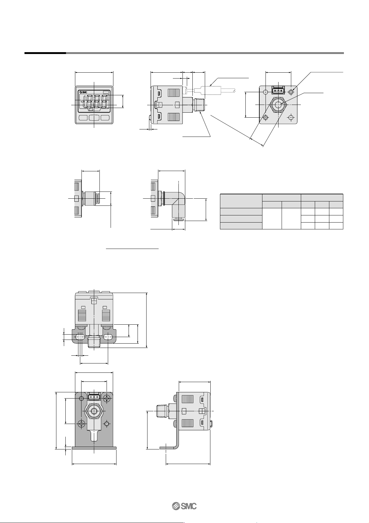
Dimensions
SET
MPa
PRESSURE
OUT
SMC
1.5
Width across flats 12
8
3.6
9.525
10
30
20 ±0.1
20 ±0.1
01: R 1/8
T1: NPT 1/8
2-M3 x 0.5
Thread depth 4
Lead wire
with connector
M5 x 0.8
A
øB
C
A
øB
With One-touch fitting
Straight Elbow
One-touch fitting
size
ø4, ø5/32"
ø6
ø1/4"
Straight
A
14.4B11.2
A
20
22.4
22.8
B
10.4
12.8
13.2
C
18
20
20.5
(mm)
Elbow
With bracket
20
20
30
35 35
1.8
45
42.5
10
3
22
15
4.2
SMC
25
30
16-2-10
Series ZSE30/ISE30
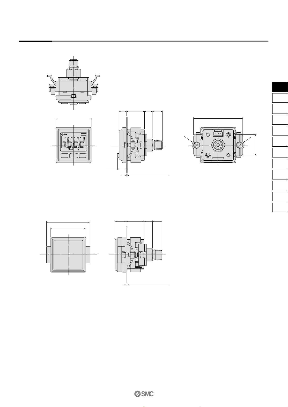
Dimensions
Panel mount adapter + Front protective cover
R4.5
R4.5
34.5
47.8
21
MADE IN JAPAN
817.87.2
8.75
9.5
Panel thickness 0.5 to 6
SET
MPa
PRESSURE
OUT
11
34.5
42.4
Panel thickness 0.5 to 6
17.8 8 9.5
Panel mount
16-2-11
ZSE
ISE
PSE
Z
I
SE3
PS
Z
I
SE
1
2
ZSP
ISA2
IS
ZSM
PF2
IF
Data
Series ZSE30/ISE30
High Precision,
2-color Display Digital Pressure Switch
SET
MPa
PRESSURE
OUT
SET
MPa
PRESSURE
OUT
SET
MPa
PRESSURE
OUT
SET
MPa
PRESSURE
OUT
SET
MPa
PRESSURE
OUT
SET
MPa
PRESSURE
OUT
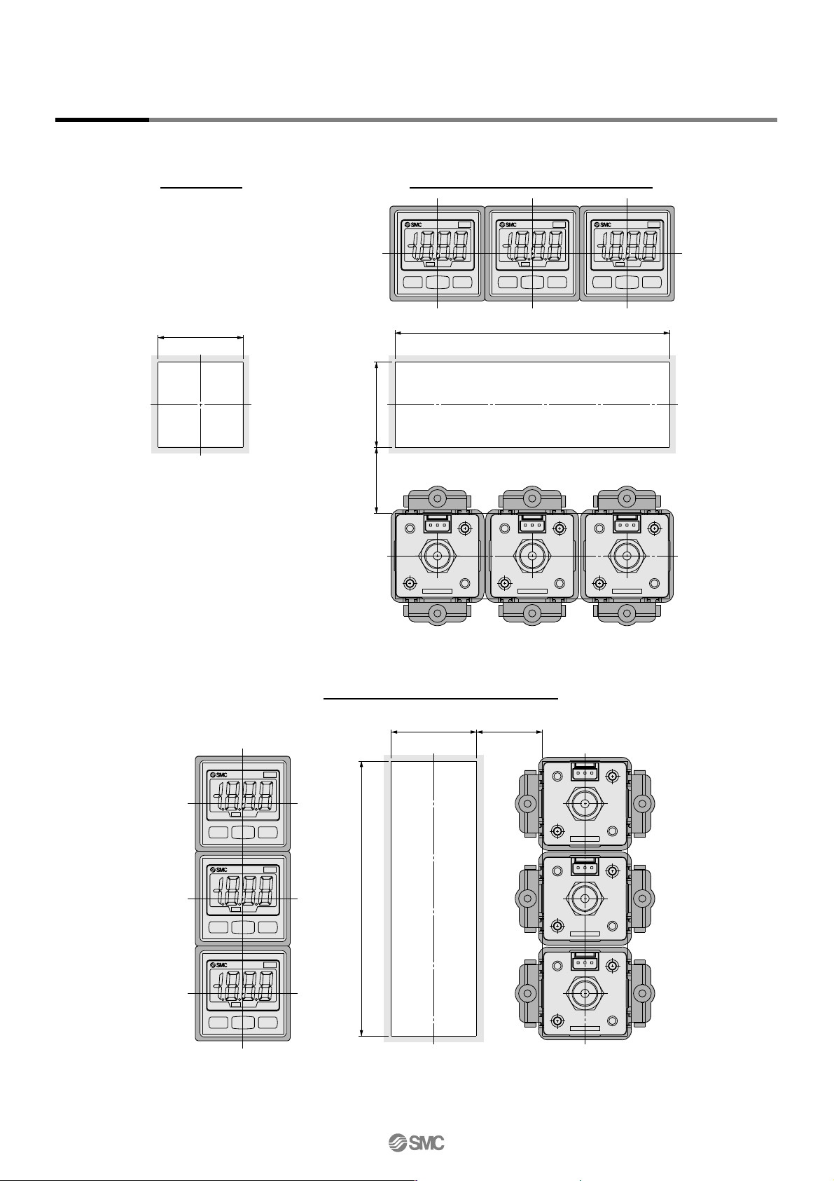
Dimensions
Panel fitting dimension
MADE IN JAPAN
MADE IN JAPAN
MADE IN JAPANMADE IN JAPAN
MADE IN JAPAN
MADE IN JAPAN
31 x n pcs. + 3.5 x (n pcs. – 1)
31
24 and up
0
–0.4
31
24 and up
31 x n pcs. + 3.5 x (n pcs. – 1)
0
–0.4
0
–0.4
31
1-pc. mounting
Multiple (2 pcs. or more) horizontal mounting
Multiple (2 pcs. or more) vertical mounting
16-2-12
Series ZSE30/ISE30
 Loading...