

SMC Networks ZSE10 Series, ZSE10F Series, ISE10 Series Installation & Maintenance Manual
ZISE##-TFM113GB
Installation & Maintenance Manual
Digital Pressure Switch
Series ZSE10/ZSE10F/ISE10
Safety Instructions
These safety instructions are intended to prevent hazardous situations
and/or equipment damage.
These instructions indicate the level of potential hazard with the labels of
"Caution", "Warning" or "Danger". They are all important notes for safety
and must be followed in addition to International standards (ISO/IEC),
Japan Industrial Standards (JIS) and other safety regulations.
To ensure safety of personnel and equipment the safety instructions in
this manual and the product catalogue must be observed, along with
other relevant safety practices.
•Do not touch the terminals and connectors while the power is on.
Otherwise electric shock, malfunction or damage to the product can result.
•After maintenance is complete, perform appropriate functional
inspections and leak tests.
Stop operation if the equipment does not function properly or there is a
leakage of fluid.
When leakage occurs from parts other than the piping, the product is
faulty.
Disconnect the power supply and stop the fluid supply.
Do not apply fluid under leaking conditions.
Safety cannot be assured in the case of unexpected malfunction.
NOTE
•The direct current power supply to be used should be UL approved as
follows:
(1) Limited voltage current circuit in accordance with UL508
A circuit which power is supplied by secondary coil of a transformer that
meets the following conditions
•Maximum voltage (with no load): less than 30Vrms (42.4V peak)
Maximum current: (1) less than 8A (including when short circuited)
(2) limited by circuit protector (such as fuse) with the
following ratings
(2) Circuit (of class 2) which is of maximum 30Vrms (42.4V peak) or less,
with UL 1310 class 2 power supply unit or UL 1585 class 2 transformer.
•The Pressure switch is a approved product only if it has a mark on the
body.
Operator error could result in serious injury or loss
of life.
In extreme conditions, there is a possibility of
serious injury or loss of life.
Operator error could result in injury or equipment
damage.
Caution
Warning
Danger
•Do not disassemble, modify (including changing the printed circuit
board) or repair.
An injury or failure can result.
•Do not operate the product outside of the specifications.
Do not use for flammable or harmful fluids.
Fire, malfunction, or damage to the product can result.
Verify the specifications before use.
•Do not operate in an atmosphere containing flammable or
explosive gases.
Fire or an explosion can result.
This product is not designed to be explosion proof.
•Do not use the product in a place where static electricity is a
problem.
Otherwise it can cause failure or malfunction of the system.
•If using the product in an interlocking circuit:
•Provide a double interlocking system, for example a mechanical
system
•Check the product regularly for proper operation
Otherwise malfunction can result, causing an accident.
•The following instructions must be followed during maintenance:
•Turn off the power supply
•Stop the air supply, exhaust the residual pressure and verify that
the air is released before performing maintenance.
Otherwise an injury can be caused.
Caution
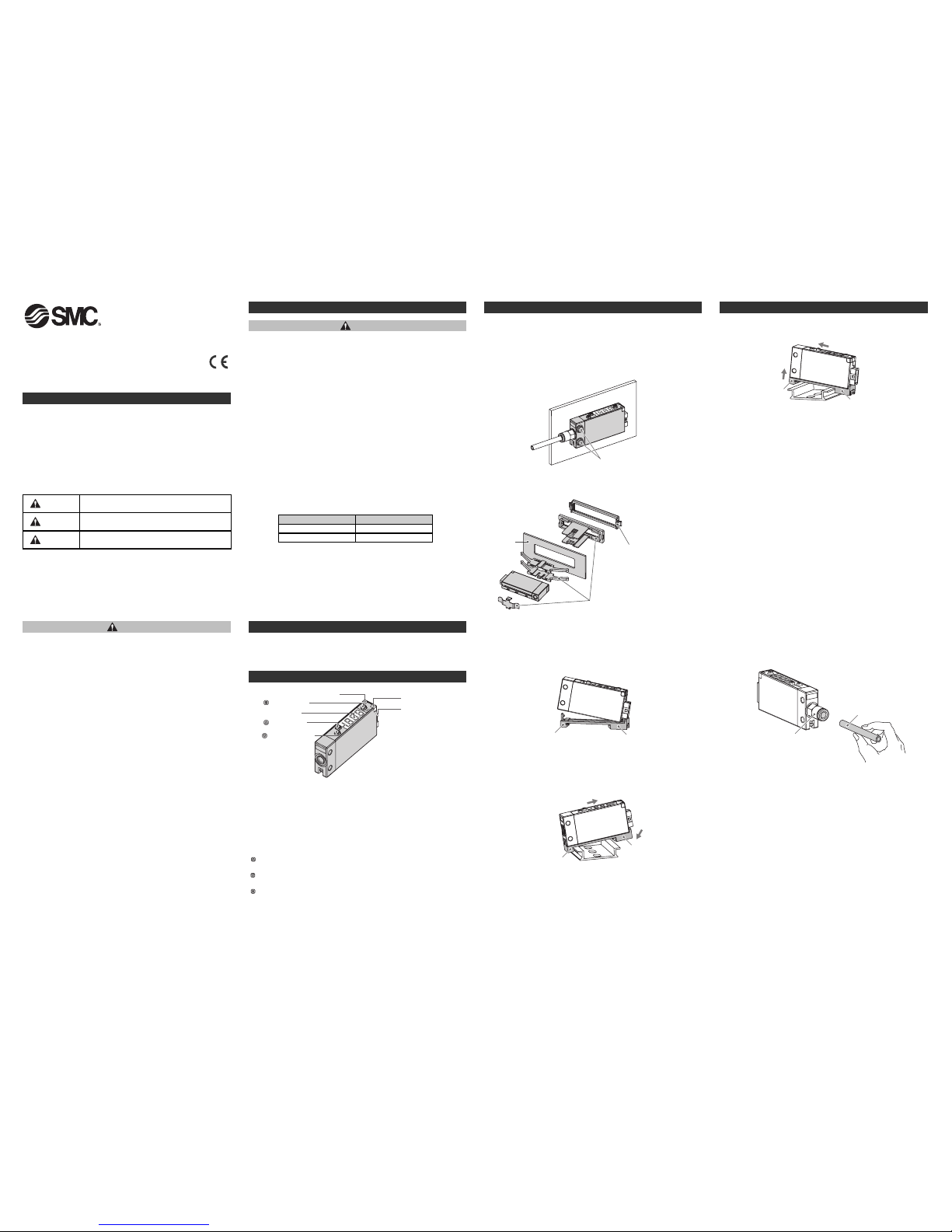
Names and Functions of Individual Parts
Installation
Model Indication and How to Order
Installation
Mounting
*: The tightening torque of piping port must be 1Nm for M5 and 7 to 9 Nm for R1/8 and
NPT1/8.
•Mount with the set screws M3 size (2 pcs.) for direct installation.
The tightening torque of the mounting screw must be 0.5 to 0.7 Nm.
Warning
Safety Instructions (Continued)
Refer to the operation manual,and catalogue for this product.
LED display
Output (OUT1) Light (Green)
button (UP)
button (SET)
button (DOWN)
Output (OUT2)
Light (Red)
Connector
Output (OUT1) Light (Green): Lights ON when the switch output (OUT1) is
turned ON.
Output (OUT2) Light (Red): Lights ON when the switch output (OUT2) is
turned ON.
LED display: Displays the current status of pressure, setting mode and error
code.
button (UP): Selects the mode or increases the ON/OFF set value.
Press this button to change to the peak display mode.
button (DOWN): Selects the mode or decreases the ON/OFF set value.
Press this button to change to the bottom display mode.
button (SET): Press this button to change to either mode and to set a
value.
No-load voltage (V peak) Max. current rating (A)
0 to 20 [V] 5.0
20 to 30 [V] 100 / peak voltage
Mounting with panel mount adapter
•Panel mount adapter + Front protective cover (Model: ZS-39-D)
Panel
Panel mount adapter
Front protective cover
Piping
Connection using One-touch fitting
1. Cut the tube perpendicularly.
2. Hold the tube and insert it into the One-touch fitting slowly until it
bottoms out.
•Allow sufficient tube length to prevent twist, tensile and moment load
from being applied to the fitting and tube.
•When using a tube manufactured by a company other than SMC,
check its outside diameter accuracy satisfies the following conditions.
1) Nylon tube:
±0.1 mm maximum
2) Soft nylon tube: ±0.1 mm maximum
3) Polyurethane tube: +0.15 mm/-0.2 mm maximum
M3
One-touch fitting
Tube
Removal and mounting of DIN rail
•It is necessary to prepare a DIN rail adapter for mounting on the DIN rail
(Model: ZS-39-R)
•Take care not to bend the claws of the DIN rail adapter when mounting.
Claw 1
Claw 2
<Mounting of DIN rail adapter>
Engage the pressure switch with claw 2 of the DIN rail adapter ,than
press down horizontally on to claw 1 until it clicks.
Claw 1
Claw 2
[1]
[2]
[3]
<Mounting on DIN rail>
Engage claw 1 of the adapter on to the DIN rail as indicated [1], apply
force in direction [2] indicated, then press downward horizontally [3] until
claw 2 clicks on to the DIN rail.
<Removal of DIN rail>
Claw 1
Claw 2
[2]
[1]
Move in the direction [1], and remove claw 1 as indicated with [2].
Installation (Continued)
MPa
kPa
Nil or M
P
Unit specification Default setting
PSI
ISE10
ZSE10(F)
Pressure range
ISE10
ZSE10(F)
ZISE##-TFM113GB
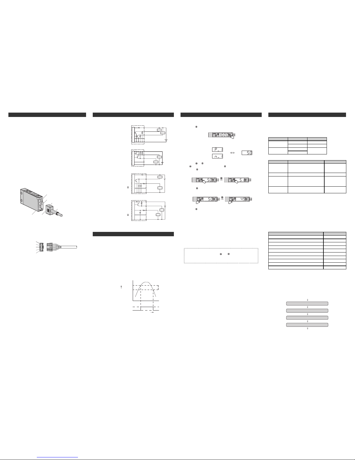
Pressure Setting
<How to operate>
•Hysteresis mode
1, Press the button once in measurement mode.
Set ON point and OFF point of the Pressure switch.
Operation
When the pressure exceeds a set point, the Pressure switch will be
turned on.
When the pressure falls below the set point by the amount of hysteresis or
more, the Pressure switch will be turned off.
The default setting of the output set value is the central value between the
atmospheric pressure and the upper limit of the rated pressure range.
If the operation shown below does not cause any problem, keep this
operation setting.
2, [P_1] or [n_1] and the set value are displayed in turn.
3, Press the or button to change the set value.
The button is for increase and the button is for decrease.
•Press the button once to increase by one figure, and press it
continuously to keep increasing the set figure.
•Press the button once to decrease by one figure, and press it
continuously to keep decreasing the set figure.
4, Press the button to finish the setting.
If 2 outputs specification is selected, [P_2] is displayed.
Set OUT2 in the same way as OUT1.
The Pressure switch operates within a set pressure range (from P1L to
P1H) during window comparator mode. Set P1L (switch lower limit) and
P1H (switch upper limit) using the setting procedure above.
Zero clear of indication
Indication is reset to zero when and buttons are pressed
simultaneously for 1 second.
For the first operation, perform zero clear without pressure supply.
Switch ON
For normal output
Switch OFF
set value
P_1
hysteresis
H_1
[Pa]
Time [s]
Pressure
Displays in turn
Normal output
Reversed output
Setting
Internal Circuit and wiring(Continued)
Internal circuit and wiring example
-B
PNP open collector 2 outputs
Max. 80 mA
Residual voltage 2 V or less
Brown DC(+)
Black OUT1
White OUT2
Blue DC(-)
Main Circuit
12 to
24 VDC
+
-
Load
Load
Grey FUNC
-C
NPN open collector 1 output
Max. 28 V, 80 mA
Residual voltage 2 V or less
Analogue voltage output
Output impedance approx. 1 k
Brown DC(+)
Main Circuit
12 to
24 VDC
Black OUT1
White OUT2
Blue DC(-)
+
-
Load
Load
Grey FUNC
-A
NPN open collector 2 outputs
Max. 28 V, 80 mA
Residual voltage 2 V or less
Brown DC(+)
Black OUT1
White OUT2
Blue DC
(-)
12 to
24 VDC
+
-
Load
Load
Grey FUNC
Main Circuit
-E
PNP open collector 1 output
Max. 80 mA
Residual voltage 2 V or less
Analogue voltage output
Output impedance approx. 1 k
Brown DC(+)
Main Circuit
12 to
24 VDC
Black OUT1
White OUT2
Blue DC(-)
+
-
Load
Load
Grey FUNC
Item
Output mode
Reversed output
Pressure setting
Hysteresis
Explanation
Selects hysteresis mode,
window comparator mode or
OFF mode.
Selects reversed output.
Sets ON point or OFF point of
the switch output.
Chattering can be prevented by
setting hysteresis.
Default setting
Hysteresis mode
Normal output
ISE10: 0.500 MPa
ZSE10: -50.5 kPa
ZSE10F: 50.0 kPa
5%
Default setting
At the time of shipment, the following settings are provided.
If the setting is acceptable, keep it for use.
To change setting, enter function selection mode.
To set each function in detail, refer to the operation manual.
•[F 0] Unit conversion function
•[F 1] Setting of OUT1
•[F 2] Setting of OUT2
Same setting as [F 1] OUT1.
[F 3] Setting of response time
[F 4] Setting of auto-preset
[F 6] Setting of fine adjustment of display value
[F11] Setting of display resolution
[F80] Setting of power saving mode
[F81] Setting of security code
[F90] Setting of all functions
[F97] Selection of copy function
[F98] Check of output
[F99] Reset to the default setting
Item
2.5 ms
Manual
0%
1000-split
OFF
OFF
OFF
OFF
Normal
OFF
Default setting
Measurement mode
The measurement mode is the condition where the pressure is detected
and indicated, and the switch function is operating.
This is the basic mode, and other modes should be selected for setting
change and other function setting changes.
Measurement mode
1s
1s
1s
Display to show the unit specification
Display to show the product
The power is supplied
1s
Display to show the standard product
Display to show the pressure range
DC(+)
Brown
Pin No.
OUT1
Black
OUT2
White
(FUNC)
Grey
DC(-) Blue
5
4
3
2
1
Internal Circuit and wiring
Wiring
Connection
•Make connection after turning the power off.
•Use a separate route for wiring to the Pressure switch.
Malfunction stemming from noise may occur if the wire is installed in the
same route as that of power or high-voltage cable.
•Be sure to ground terminal FG when using a commercially available
switch-mode power supply. When the switch-mode power supply is
connected to the Pressure switch, switching noise will be
superimposed and product specification can no longer be met. This can
be prevented by inserting a noise filter, such as a line noise filter and
ferrite core, between the switch-mode power supply and the Pressure
switch, or by using a series power supply instead of the switch-mode
power supply.
Connector
Connecting/Disconnecting
•When mounting the connector, insert it straight into the socket, holding
the lever and connector body, and fit the hook of the lever into the
groove in the housing to lock.
•When removing the connector, press down the lever to release the hook
from the groove and pull the connector straight out.
Housing
Socket
Connector
Groove
Lever
Cable
(Model: ZS-39-5G)
Pin No. of the Connector
Setting (Continued) Setting (Continued)
To set [F 2] setting of OUT2 in detail, refer to the operation manual.
•Window comparator mode
 Loading...