

SMC Networks ISA3-G series, ISA3-H series, ISA3-F series Operation Manual

No.PS※※-OMR0002-G
PRODUCT NAME
Digital Gap Checker
MODEL / Series / Product Number
ISA3 series
-1-
No.PS※※-OMR0002-G
Table of Contents
1 Before Use
Safety Instructions 2
2 About this product
Features 7
Model Indication and How to Order 8
Summary of Product parts 14
Specification 15
Specifications (ISA3) ··································· 15
Specifications (Regulator) ····························· 16
Specifications (2 port solenoid valve) ··············· 16
Characteristics graph ··································· 17
Dimensions ··············································· 20
3 Installation
Mounting and Installation 26
Piping ······················································ 26
Installation ················································· 29
Wiring ······················································ 34
Part structure ············································· 38
4 How to use
Outline of setting 41
Measurement mode ···································· 42
Switch Point Setting 44
Switch point change mode ···························· 44
Table of default settings ································ 44
Preparation before setting ····························· 45
Setting······················································ 45
Function Setting 46
Function selection mode ······························· 46
Table of default settings ································ 46
Key lock (Security code setting) 58
5 Troubleshooting
Maintenance 59
Troubleshooting 60
Error indication ··········································· 61
Relationship between
Supply Pressure and Display ························· 61
1 Before Use
-2-
No.PS※※-OMR0002-G
Safety Instructions
These safety instructions are intended to prevent hazardous situations and/or equipment damage.
These instructions indicate the level of potential hazard with the labels of "Caution", "Warning" or "Danger".
They are all important notes for safety and must be followed in addition to International Standards
(ISO/IEC)*1), and other safety regulations.
*1) ISO 4414: Pneumatic fluid power -- General rules relating to systems.
ISO 4413: Hydraulic fluid power -- General rules relating to systems.
IEC 60204-1: Safety of machinery -- Electrical equipment of machines .(Part 1: General requirements)
ISO 10218: Manipulating industrial robots -Safety.
etc.
Caution
Caution indicates a hazard with a low level of risk which, if not avoided, could
result in minor or moderate injury.
Warning
Warning indicates a hazard with a medium level of risk which, if not avoided,
could result in death or serious injury.
Danger
Danger indicates a hazard with a high level of risk which, if not avoided, will
result in death or serious injury.
Warning
1. The compatibility of the product is the responsibility of the person who designs the
equipment or decides its specifications.
Since the product specified here is used under various operating conditions, its compatibility with specific
equipment must be decided by the person who designs the equipment or decides its specifications
based on necessary analysis and test results.
The expected performance and safety assurance of the equipment will be the responsibility of the
person who has determined its compatibility with the product.
This person should also continuously review all specifications of the product referring to its latest catalog
information, with a view to giving due consideration to any possibility of equipment failure when
configuring the equipment.
2. Only personnel with appropriate training should operate machinery and equipment.
The product specified here may become unsafe if handled incorrectly.
The assembly, operation and maintenance of machines or equipment including our products must be
performed by an operator who is appropriately trained and experienced.
3. Do not service or attempt to remove product and machinery/equipment until safety is
confirmed.
1. The inspection and maintenance of machinery/equipment should only be performed after measures to
prevent falling or runaway of the driven objects have been confirmed.
2. When the product is to be removed, confirm that the safety measures as mentioned above are
implemented and the power from any appropriate source is cut, and read and understand the specific
product precautions of all relevant products carefully.
3. Before machinery/equipment is restarted, take measures to prevent unexpected operation and malfunction.
4. Contact SMC beforehand and take special consideration of safety measures if the
product is to be used in any of the following conditions.
1. Conditions and environments outside of the given specifications, or use outdoors or in a place
exposed to direct sunlight.
2. Installation on equipment in conjunction with atomic energy, railways, air navigation, space, shipping,
vehicles, military, medical treatment, combustion and recreation, or equipment in contact with food and
beverages, emergency stop circuits, clutch and brake circuits in press applications, safety equipment or
other applications unsuitable for the standard specifications described in the product catalog.
3. An application which could have negative effects on people, property, or animals requiring special
safety analysis.
4. Use in an interlock circuit, which requires the provision of double interlock for possible failure by using
a mechanical protective function, and periodical checks to confirm proper operation.
1 Before Use
-3-
No.PS※※-OMR0002-G
Safety Instructions
Caution
1.The product is provided for use in manufacturing industries.
The product herein described is basically provided for peaceful use in manufacturing industries.
If considering using the product in other industries, consult SMC beforehand and exchange
specifications or a contract if necessary.
If anything is unclear, contact your nearest sales branch.
Limited warranty and Disclaimer/Compliance Requirements
The product used is subject to the following "Limited warranty and Disclaimer" and "Compliance
Requirements".
Read and accept them before using the product.
Limited warranty and Disclaimer
1. The warranty period of the product is 1 year in service or 1.5 years after the product is
delivered,whichever is first.2)
Also, the product may have specified durability, running distance or replacement parts.
Please consult your nearest sales branch.
2. For any failure or damage reported within the warranty period which is clearly our
responsibility, a replacement product or necessary parts will be provided.
This limited warranty applies only to our product independently, and not to any other
damage incurred due to the failure of the product.
3. Prior to using SMC products, please read and understand the warranty terms and
disclaimers noted in the specified catalog for the particular products.
2) Vacuum pads are excluded from this 1 year warranty.
A vacuum pad is a consumable part, so it is warranted for a year after it is delivered.
Also, even within the warranty period, the wear of a product due to the use of the
vacuum pad or failure due to the deterioration of rubber material are not covered by the
limited warranty.
Compliance Requirements
1. The use of SMC products with production equipment for the manufacture of weapons of
mass destruction (WMD) or any other weapon is strictly prohibited.
2. The exports of SMC products or technology from one country to another are governed by
the relevant security laws and regulation of the countries involved in the transaction. Prior
to the shipment of a SMC product to another country, assure that all local rules governing
that export are known and followed.
Caution
SMC products are not intended for use as instruments for legal metrology.
Products that SMC manufactures or sells are not measurement instruments that are qualified by pattern
approval tests relating to the measurement laws of each country.
Therefore, SMC products cannot be used for business or certification ordained by the measurement laws of
each country.
1 Before Use
-4-
No.PS※※-OMR0002-G
■Important
In order to use this product safely, be sure to read and follow the instructions given in "Pressure
switches/Flow switches common precautions" which can be found under "Handling Precautions for
SMC Products" on the SMC website, before use.
■Operator
This operation manual is intended for those who have knowledge of machinery using pneumatic
equipment, and have sufficient knowledge of assembly, operation and maintenance of such
equipment. Only those persons are allowed to perform assembly, operation and maintenance.
Read and understand this operation manual carefully before assembling, operating or providing
maintenance to the product.
■Specific product precautions
Warning
About this product
This product is not designed to be explosion proof.
Do not use a fluid containing chemicals, synthetic oils including organic solvent, salt and
corrosive gases.
Otherwise damage to the product, malfunction and failure can result.
Writing time of input data to product is 1000000 times.
Design
The product should be positioned higher than the detection nozzle.
If the product is positioned lower than the detection nozzle, water or oil may enter the detection port, causing a
malfunction or operational failure.
Do not use multiple detection nozzles with one product.
Correct measurement may not be possible. If multiple nozzles are to be used, please test them on the actual
equipment. It is necessary for the user to verify correct operation.
1 Before Use
-5-
No.PS※※-OMR0002-G
Warning
Mounting/Installation
If the entering of foreign material to the fluid is possible, install the filter (5 m or less) or the
mist separator to the upstream side.
If compressed air containing condensate is used, install the air dryer or the drain catch before
the filter, and perform drainage regularly.
If regular drainage is difficult, the use of a filter with an auto drain is recommended.
Piping
Eliminate any dust left in the piping by air blow before connecting the piping to the product.
Otherwise it can cause damage to the product, malfunction or failure.
Perform function and leakage inspection after piping.
Safety cannot be assured in the case of unexpected malfunction. Disconnect the power supply and stop the fluid
supply if the equipment does not function properly or if there is leakage of fluid.
Do not use equipment or fittings that may leak or obstruct the air flow between the product and
the detection nozzle.
Wiring
The product is CE marked, but not immune to lightning strikes. Take measures against
lightning strikes in the system.
Limit of the cable tensile force is 50 N.
Do not lift or carry the product by holding the cables.
If the lead wire can move, fix it near the body of the product.
Keep wiring as short as possible to prevent interference from electromagnetic noise and surge
voltage.
Do not use a cable longer than 10 m.
Wire the DC (-) line (blue) as close as possible to the power supply.
Operating environment
Do not use the product in an environment where the product is constantly exposed to water or
oil splashes.
Otherwise it can cause failure or malfunction. Take measures such as using a cover.
Do not use in an atmosphere containing oil, corrosive gases, chemicals, sea water, or where
there is direct contact with any of these.
Even exposure for a short period of time, will have adverse effects including damage, failure, malfunction and
hardening of the cable.
Do not use the product in the presence of a magnetic field.
Otherwise malfunction can result.
Do not operate close to a heat source, or in a location exposed to radiant heat.
Otherwise malfunction can result.
When the product is contained in a box for use, provide an exhaust port for constant release
of pressure to atmosphere.
If the pressure in the box is not atmospheric pressure, correct inspection will not be available and malfunction may
result.
1 Before Use
-6-
No.PS※※-OMR0002-G
Warning
Usage
Do not short-circuit the load.
When the load is short circuit, generated excess current lead to cause the damage of the product.
Do not press the setting buttons with a sharp pointed object.
It may damage the setting buttons.
During the any setting, the product will switch the output according to the existing settings
until the changes are complete.
Confirm the output has no adverse effect on machinery and equipment before setting.
Stop the control system before setting if necessary.
Perform settings suitable for the operating conditions.
Incorrect setting can cause operation failure.
For details of each setting, refer to each “Setting” 41 page of this manual.
Do not touch the LCD during operation.
The display can vary due to static electricity.
Maintenance Service
Drain system regularly.
If condensate enters the secondary side, it may cause malfunction of pneumatic equipment.
◆Please read and understand the cautions in the Operation Manuals for
VX2 series (2 port solenoid valve) and AR20 series (Regulator) before
use.
2 About this product
-7-
No.PS※※-OMR0002-G
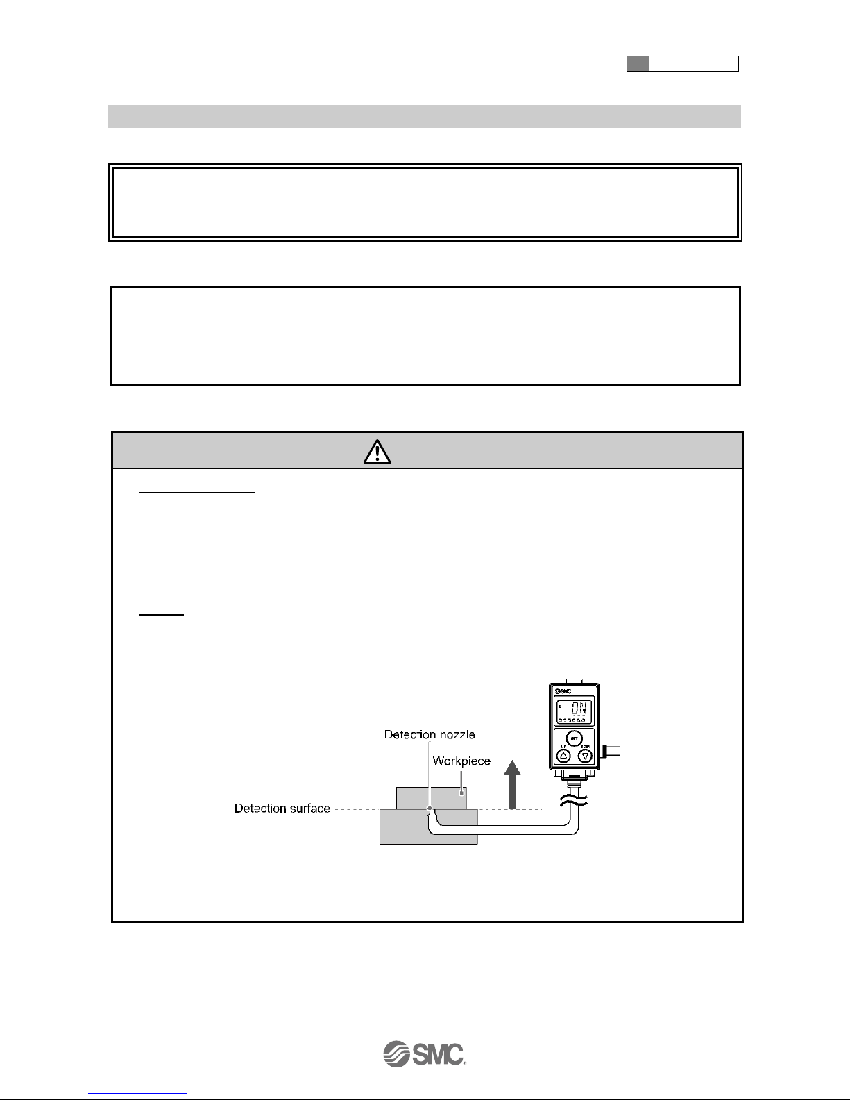
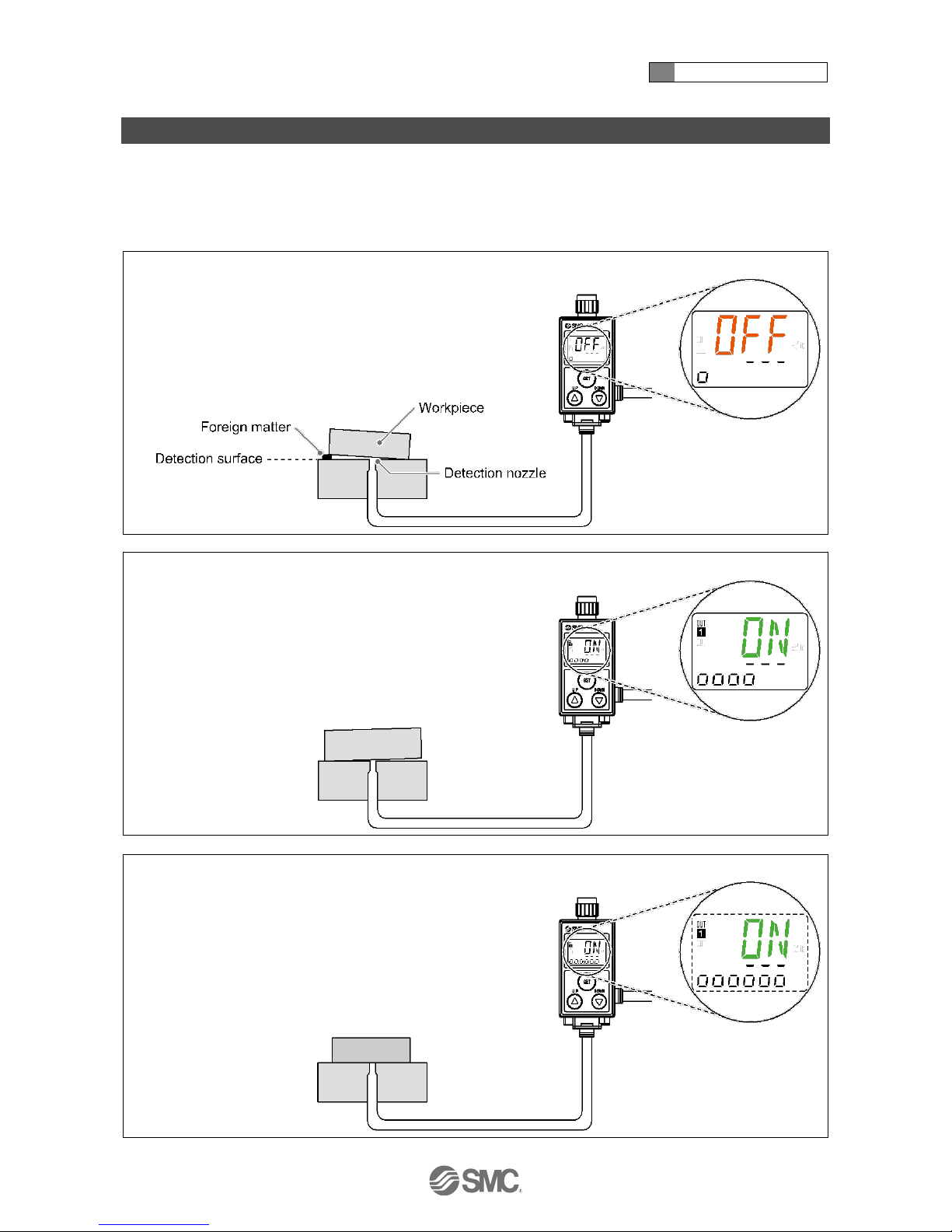
Features
The Gap between the detection surface and the workpiece (0.01 mm to 0.03 mm, 0.02 mm to 0.15 mm,
0.05 mm to 0.30 mm) can be detected.
The Gap condition is indicated on the main screen in Green (ON) or Orange (OFF). : Default setting.
The sub screen indicates the distance between the detection surface and the workpiece using a level meter.
This product is a non-contact switch which will not scratch the workpiece.
(A) The Workpiece is not seated in the correct position due to a foreign object.
(B) Within the acceptable range (Seats correctly).
(C) The Workpiece is more closely in contact than in (B).
2 About this product
-8-
No.PS※※-OMR0002-G
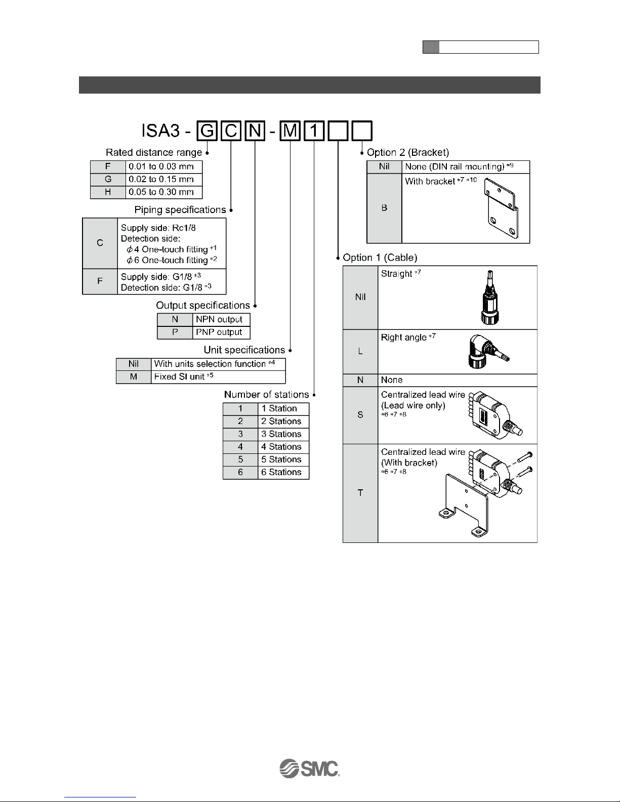
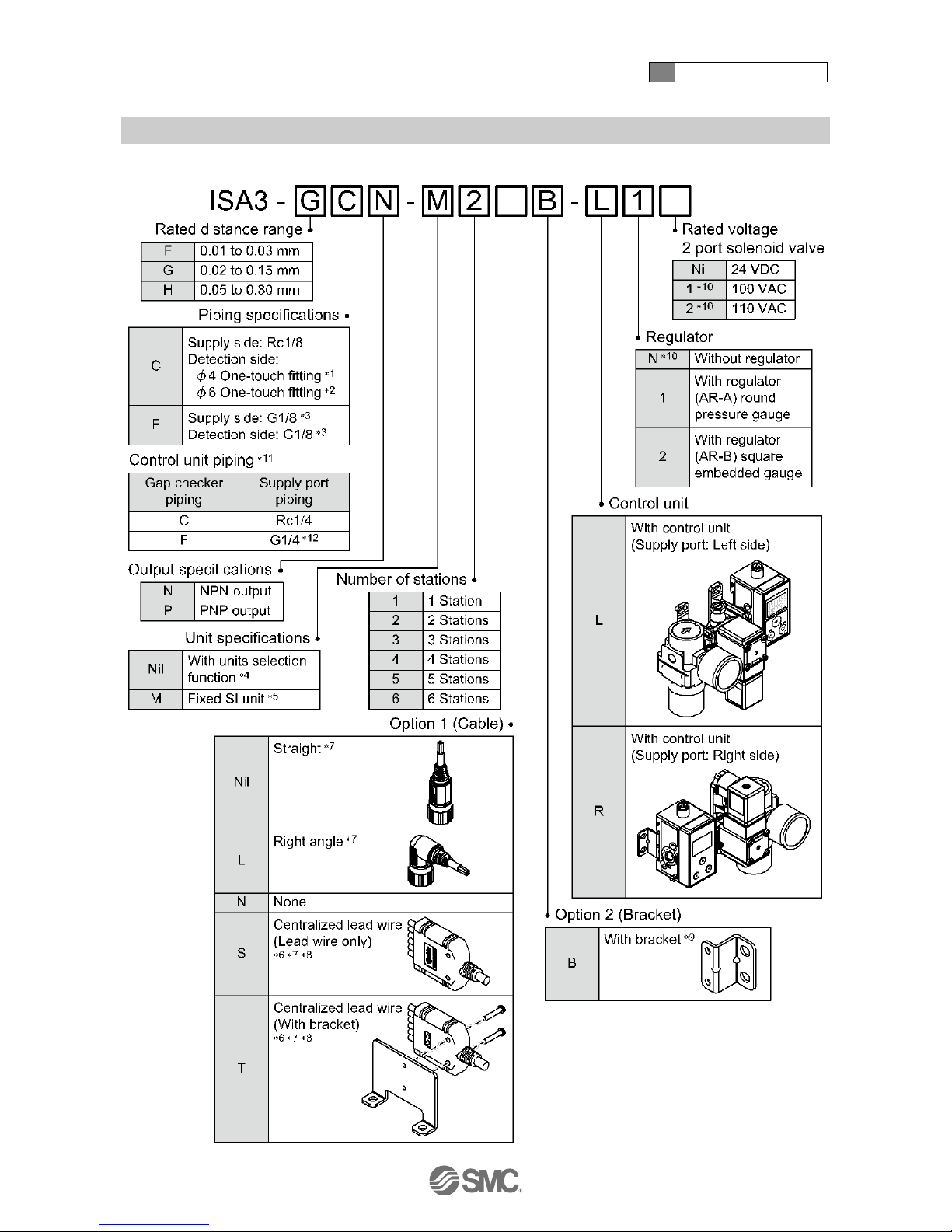
Model Indication and How to Order
○Without control unit
1: To be used for the rated distance range of "F".
2: To be used for the rated distance range of "G" or "H".
3: ISO1179-1
4: The new Measurement Law prohibits the use of pressure switch with the units selection function in Japan.
5: Fixed unit: kPa
6: Cannot be selected for 1 station.
7: At the factory, the options are not attached to the product, but packed together with it for shipment.
8: Refer to 8 (page 10).
9: DIN rail must be ordered separately.
10: About the number of brackets.
1 station: 1 piece is packed
More than 2 stations: 2 pieces is packed
2 About this product
-9-
No.PS※※-OMR0002-G
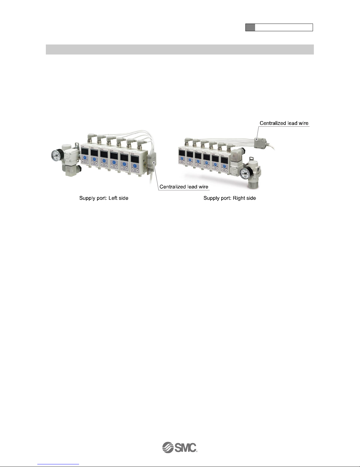
○With control unit
2 About this product
-10-
No.PS※※-OMR0002-G
1: To be used for the rated distance range of "F".
2: To be used for the rated distance range of "G" or "H".
3: ISO1179-1
4: The new Measurement Law prohibits the use of pressure switch with the units selection function in Japan.
5: Fixed unit: kPa
6: Cannot be selected for 1 station.
7: At the factory, the options are not attached to the product, but packed together with it for shipment.
8: The electrical entry of centralized lead wire for M12 connector is on the right side.
If the supply port on the right side is used, arrange the centralized lead wire so that it does not interfere with the control unit.
9: The bracket for control unit will be assembled before shipment.
10: Made to order
11: When the control unit is mounted, the piping specifications of the supply port will be changed due to piping specification of the gap
checker.
12: ISO16030
2 About this product
-11-
No.PS※※-OMR0002-G
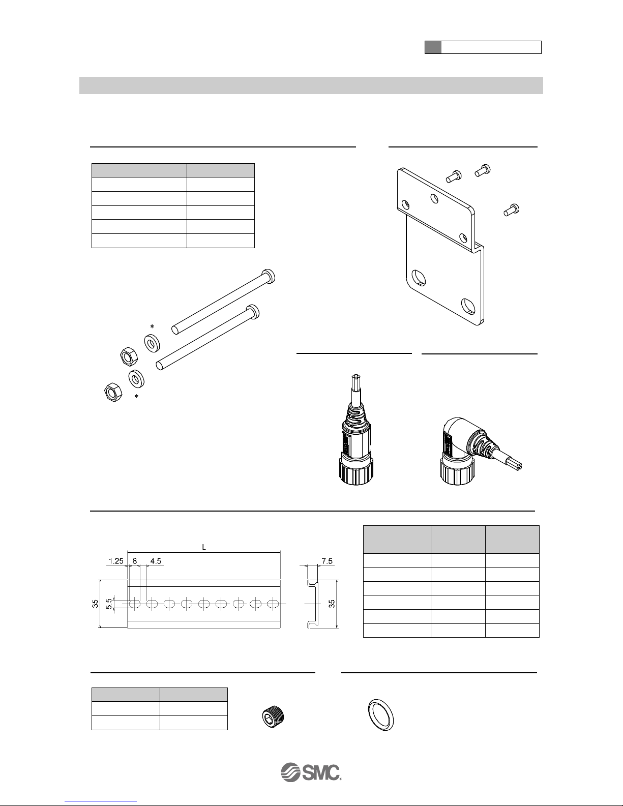
○Option/Part number
Joint screws
(2 screws, 2 spacers
, 2 nuts)
ISA-16-
Bracket (when control unit not fitted)
(Nominal size:3 x 8, 3 screws)
ISA-14
Number of stations
Part number
2
ISA-16-2
3
ISA-16-3
4
ISA-16-4
5
ISA-16-5
6
ISA-16-6
: Spacers are included for 4 and 6 stations.
With connector cable
ZS-31-B
With connector cable
ZS-31-C
DIN rail
ISA-5-
Part number
L
Number of
stations
ISA-5-1
73.0
1
ISA-5-2
135.5
2
ISA-5-3
173.0
3
ISA-5-4
210.5
4
ISA-5-5
248.0
5
ISA-5-6
285.5
6
Threaded plug with seal
ISA-12-
Seal for extra station
ISA-15
Piping type
Part number
Rc1/8
ISA-12-A
G1/8
ISA-12-C
: This is applicable in both
piping specification C and F.
2 About this product
-12-
No.PS※※-OMR0002-G
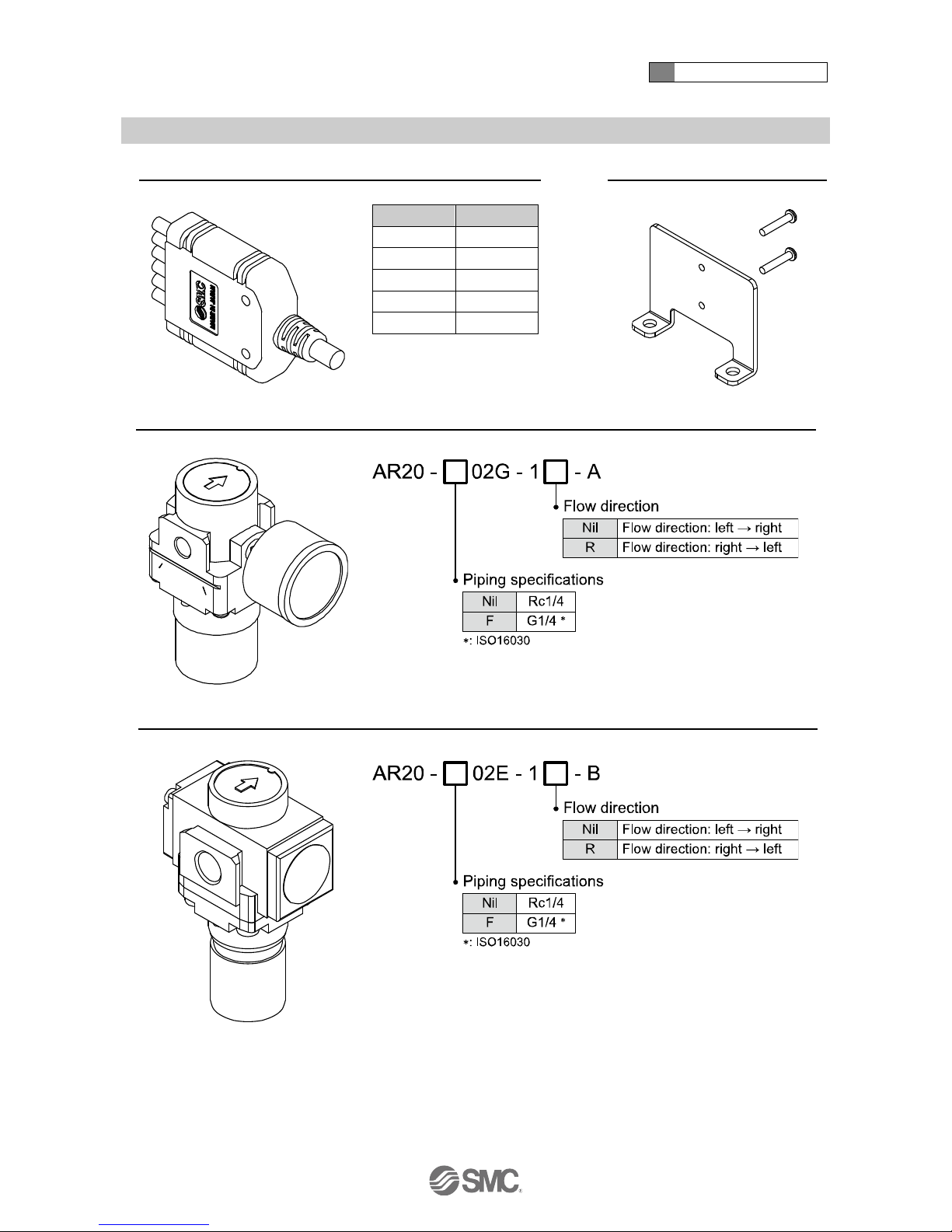
Centralized lead wire
ISA-19-
Bracket for centralized lead wire
ISA-20
Stations
Model
2
ISA-19-2
3
ISA-19-3
4
ISA-19-4
5
ISA-19-5
6
ISA-19-6
Regulator (Round pressure gauge)
AR20-02G-1-A
Regulator (Square embedded gauge)
AR20-02E-1-B
2 About this product
-13-
No.PS※※-OMR0002-G
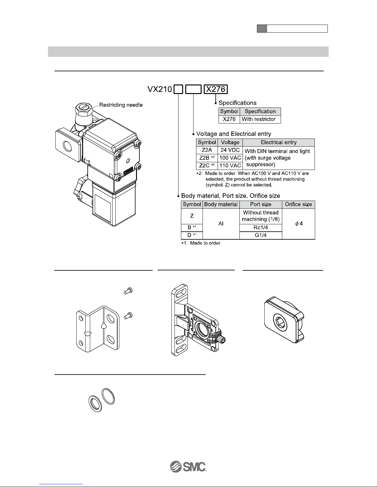
2 port solenoid valve
VX210X276
Bracket (when control unit fitted)
(Nominal size:3 x 8, 2 screws)
ISA-17
Spacer with bracket
Y200T-A
Modular adapter
E210-U01
Spacer
ISA-18
With O-ring
: When a 2 port solenoid valve is connected to the right.
2 About this product
-14-
No.PS※※-OMR0002-G
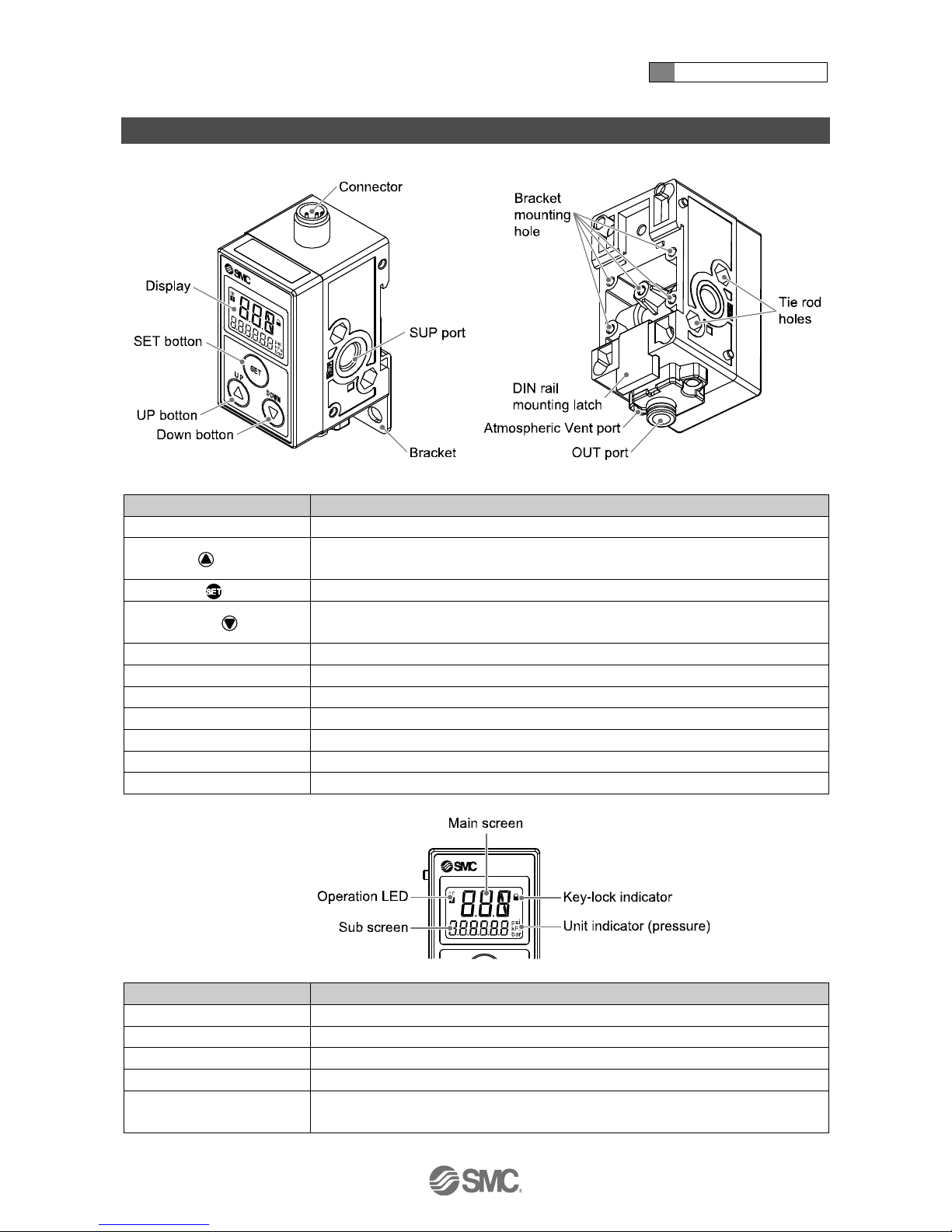
Summary of Product parts
Element
Description
Display
See below
UP button ( button)
Selects the mode and the display shown on the sub screen, or increases the switch
point.
SET button ( button)
Press this button to change the mode and to fix the settings.
DOWN button ( button)
Selects the mode and the display shown on the sub screen, or decreases the switch
point.
Connector
Electrical connection.
SUP port (Supply port)
Port to supply pressure.
Bracket mounting hole
Used to attach the bracket to the product.
Tie rod holes
Used to connect additional products.
OUT port (Detection port)
Port to be connected to the detection nozzle.
Atmospheric vent port
Port to vent exhaust air to the atmosphere.
DIN rail mounting latch
Used to mount the product on a DIN rail.
Display
Element
Description
Main screen
ON/OFF, display value and error code are displayed. (2 colour display)
Operation LED
Indicates the switch output status. Turns ON (orange) when the switch output is ON.
Sub screen
Level meter, display value, switch point, pressure etc. are displayed.
Key-lock indicator
Turns ON when keys are locked.
Unit indicator (pressure)
When pressure is displayed on the sub screen, indicates the pressure unit currently
selected.
2 About this product
-15-
No.PS※※-OMR0002-G
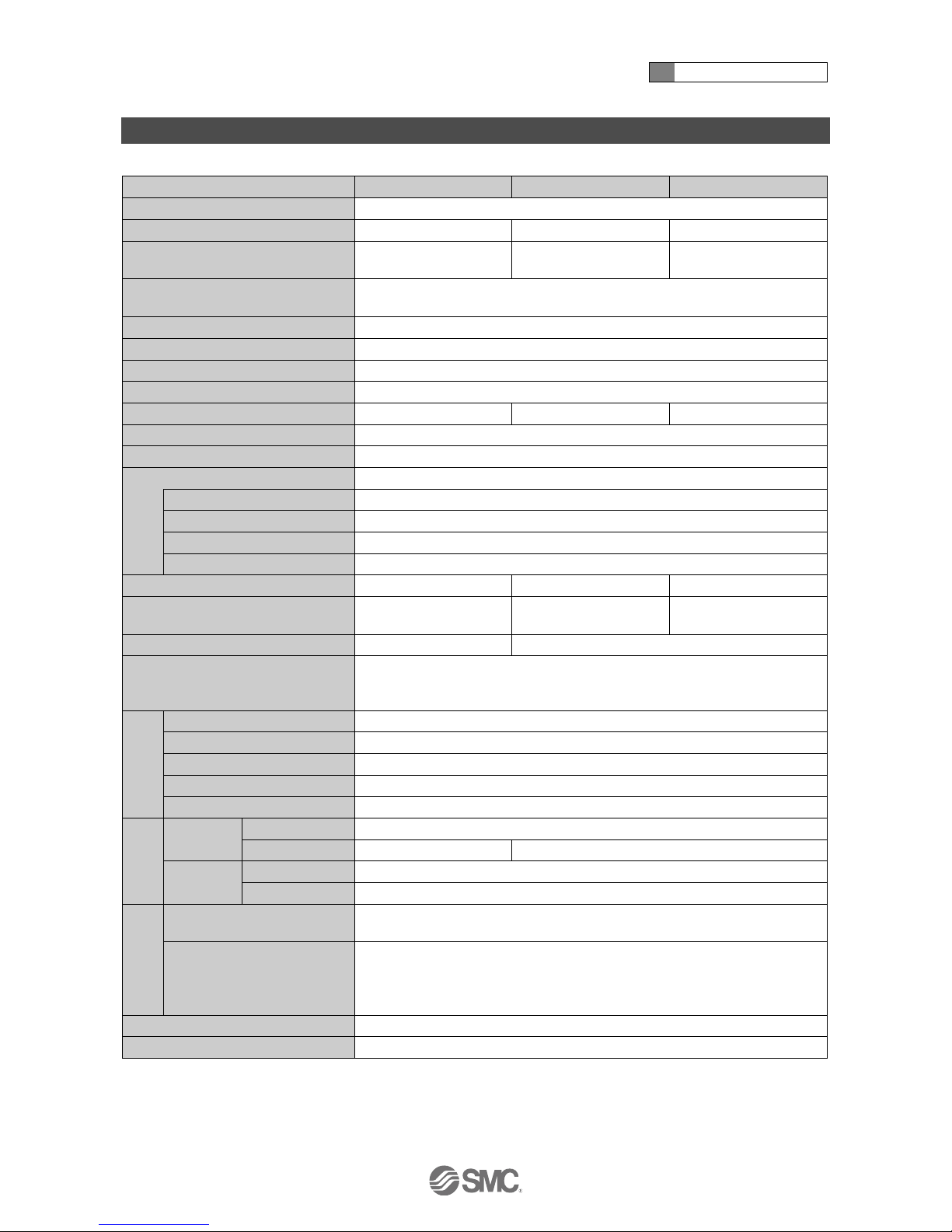
Specification
■Specifications (ISA3)
Model
ISA3-F
ISA3-G
ISA3-H
Applicable fluid
Dry air (Filtered through a 5 μm filter)
Rated distance range
0.01 to 0.03 mm
0.02 to 0.15 mm
0.05 to 0.30 mm
Displayable/Settable range
(Distance reference)
1
0 to 60
2
10 to 300
2
30 to 500
2
Minimum display resolution
(Distance reference)
1
1
Rated pressure range
100 to 200 kPa
Displayable range (Pressure value)
3
-20 to 220 kPa
Withstand pressure
600 kPa
Detection nozzle
1.5
4
Current flow
5 L/min or less
12 L/min or less
22 L/min or less
Power supply voltage
24 VDC 10%, Ripple(p-p) 10% or less (with power supply polarity protection)
Current consumption
25 mA or less
Switch output
1 output (NPN or PNP)
Max. load current
10 mA
Max. applied voltage
26.4 V
Residual voltage
1 V or less (at 10 mA)
Short circuit protection
Provided
Repeatability
0.005 mm or less
0.010 mm or less
0.020 mm or less
Temperature characteristics
(Reference: 25 oC)
0.010 mm or less
0.015 mm or less
0.030 mm or less
Hysteresis
0 to variable (Default: 3)
0 to variable (Default: 20)
Display
2-screen display LCD
Main screen: 3-digit, 7-segment 2-colour (Orange/Green)
Sub screen: 6-digit, 7-segment 1-colour (White)
Environment
Enclosure
IP67 equivalent
Operating temp. range
Operation: 0 to 50 oC, Stored: -20 to 70 oC (No condensation or freezing)
Operating humidity range
Operation/Stored: 35 to 85% RH (No condensation)
Withstand voltage
1000 VAC or more (in 50/60 Hz) for 1 minute between terminals and housing
Insulation resistance
2 MΩ or more at 500 VDC, between terminals and housing
Piping
spec.
Piping
option C
Supply port
Rc1/8
Detection port
4 One-touch fitting
6 One-touch fitting
Piping
option F
Supply port
G1/8 (ISO1179-1)
Detection port
G1/8 (ISO1179-1)
Cable
Lead wire with connector
M12 lead wire with 4 pin connector, 4 cores, 4, 5 m
Conductor O.D.: 0.72 mm, Insulator O.D.: 1.14 mm
Centralized lead wire
M12 lead wire with 4 pin connector part, 4 cores, 4, Insulator O.D.: 1.14 mm
Centralized lead wire part, 2 to 3 stations: 5 cores, 4, 5 m
4 to 6 stations: 8 cores, 6, 5 m
Conductor O.D.: 0.50 mm, Insulator O.D.: 1.00 mm (2 to 6 stations common)
Weight
113 g (Cable not included, One-touch fitting)
Standard
CE, RoHS compliant
1: Refer to the Characteristics Curve on page 19 for the relationship between the display value and the detected distance.
2: For ISA3-F type, the range is up to 57, with a hysteresis of 3.
For ISA3-G type, the range is up to 280, with a hysteresis of 20.
For ISA3-H type, the range is up to 480, with a hysteresis of 20.
3: The Pressure value will be indicated on the sub screen.
4: Refer to page 27 for details of the detection nozzle.

2 About this product
-16-
No.PS※※-OMR0002-G
■Specifications (Regulator)
Refer to the standard regulator catalogue for detailed specifications.
■Specifications (2 port solenoid valve)
Refer to "Option/Part number" (page 13) or the catalogue of the standard 2 port solenoid valve for the
detailed specifications of models other than X276.
2 About this product
-17-
No.PS※※-OMR0002-G
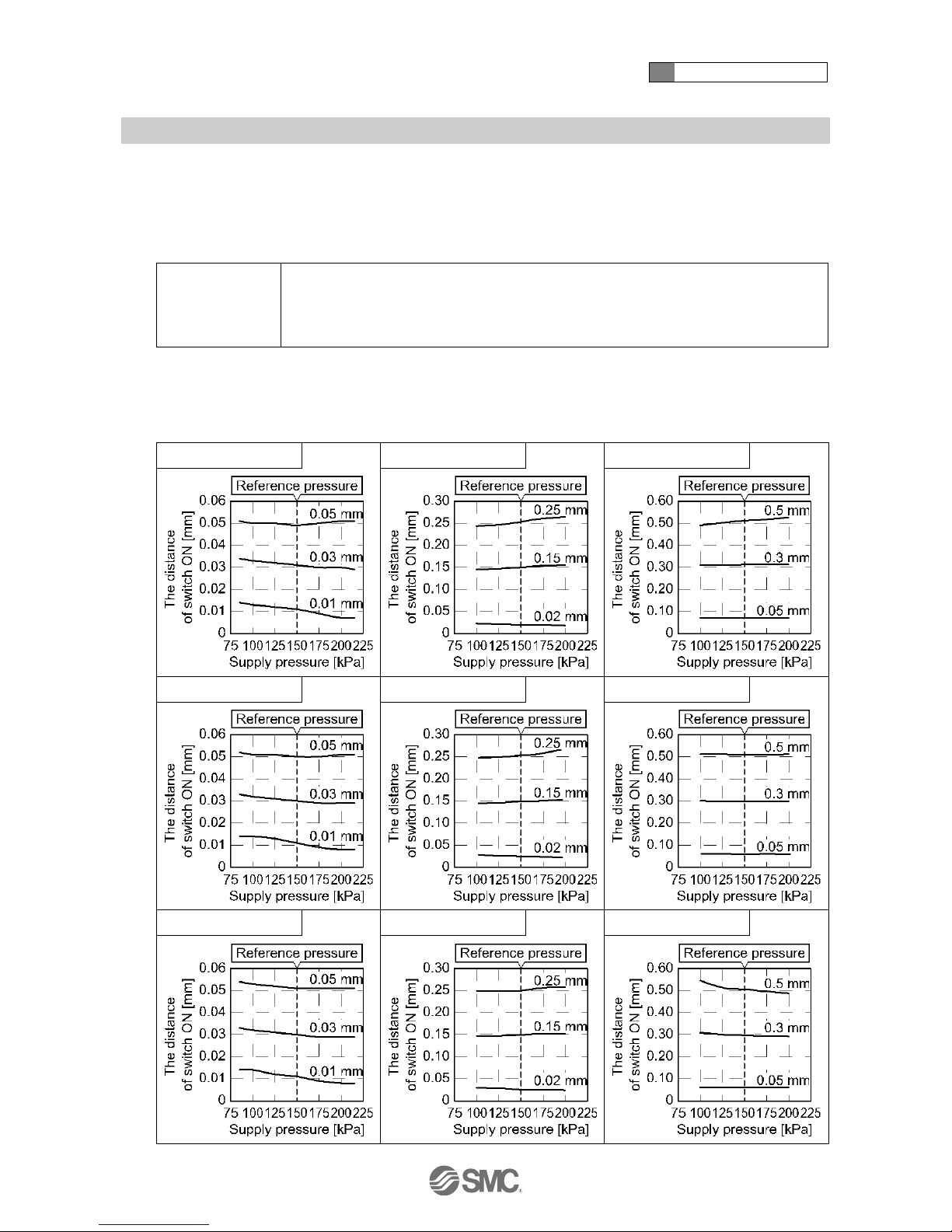
■Characteristics graph
○Supply pressure dependence characteristics
The detection distance for turning ON the output depends on the supply pressure.
The graphs below show the variation of the distance for the product to turn ON, for 3 types of gap, by
changing the supply pressure (50 kPa) when the product is set to turn ON at 150 kPa supply pressure.
Test conditions
Detection nozzle: ø1.5
Piping: F type: ø4 x ø2.5 tube
G, H type: ø6 x ø4 tube
Reference pressure: 150 kPa
: Use within the rated pressure range (100 kPa to 200 kPa).
It will be impossible to measure the gap when the operating pressure is less than 80 kPa or more than 220 kPa. And the output
will be OFF.
ISA3-F
ISA3-G
ISA3-H
Piping length: 1 m
Piping length: 1 m
Piping length: 1 m
Piping length: 3 m
Piping length: 3 m
Piping length: 3 m
Piping length: 5 m
Piping length: 5 m
Piping length: 5 m

2 About this product
-18-
No.PS※※-OMR0002-G
○Response time
Response time is the elapsed time between the pressure supply and the turning ON of the switch output.
The Response time varies depending on the piping length from the OUT port to the detection nozzle, and
the seating condition of the workpiece.
The graphs below show the response time when the workpiece is approached at 90% distance and 0%
distance (close contact). (: The switch point is 100% distance)
(Example: When the switch point is set to 0.1 mm, the response time when the workpiece is at 0.09 mm
and 0.00 mm are measured).
Test conditions
Detection nozzle: ø1.5
Piping: F type: ø4 x ø2.5 tube
G, H type: ø6 x ø4 tube
Supply pressure: 200 kPa
ISA3-F
ISA3-G
ISA3-H
Piping length: 1m
Piping length: 1m
Piping length: 1m
Piping length: 3 m
Piping length: 3 m
Piping length: 3 m
Piping length: 5 m
Piping length: 5 m
Piping length: 5 m
 Loading...