

SMC Networks IP6000, IP6100 Installation And Maintenance Manual
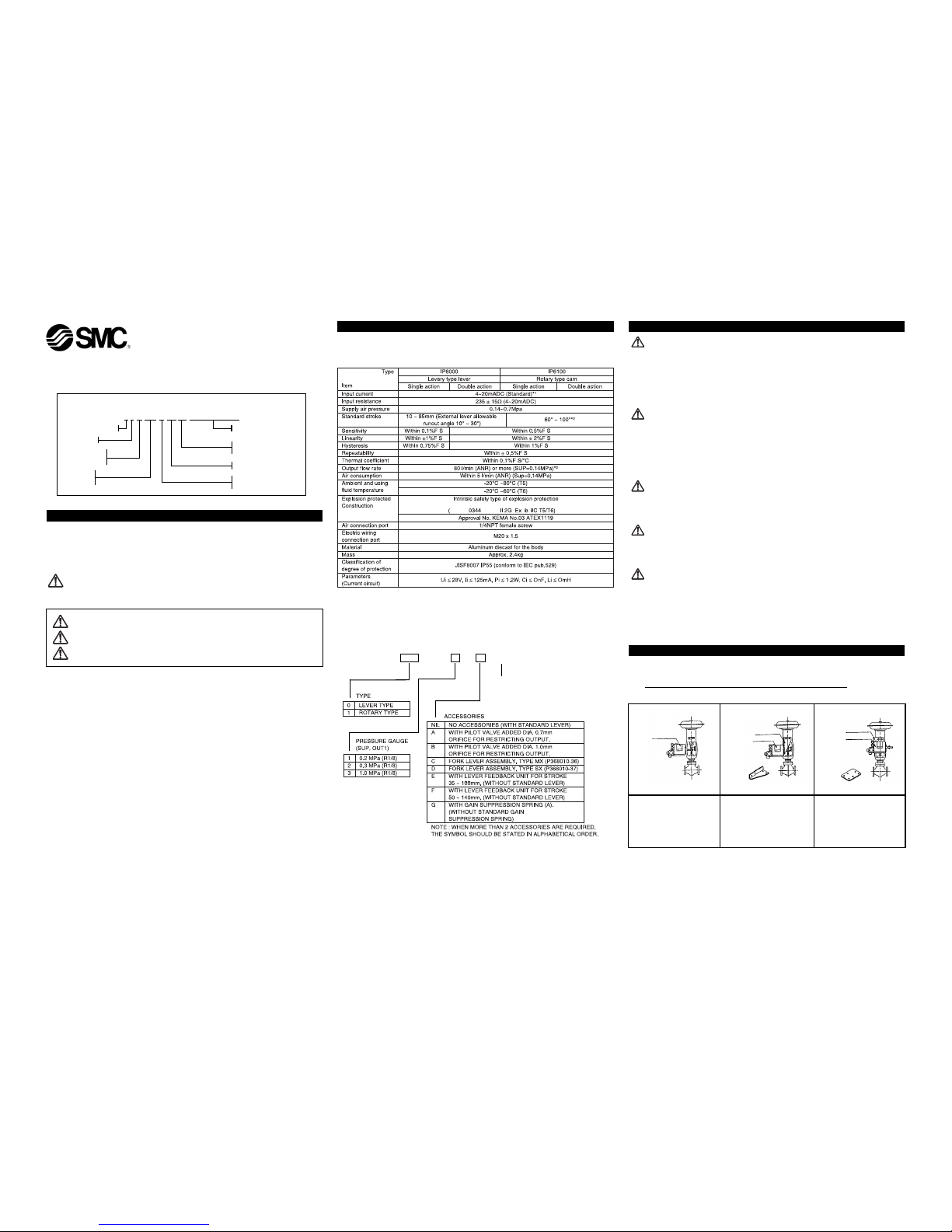
2 SPECIFICATIONS
Protect the unit from impact and dropping during transfer and when mounted. It may cause failure of the unit.
y Do not use the unit in places with high humidity & temperature. It may cause malfunctions.
y Do not use this positioner outside of the range of it's specifications as this can cause failure.
*1 : 1/2 split range is possible with the standard type (by adjusting the span)
*2 : The stroke is adjustable in 0~60° and 0~100°.
*3 : Standard air (JIS B0120): temp.20°C, absolute press. 760mmHg, ratio humidity 65%.
2.1 How to Order
1 SAFETY RECOMMENDATION
1.1 General recommendation
These safety instructions are intended to prevent a hazardous situation and/or equipment damage. These
instructions indicate the level of potential hazard by label of "Caution", "Warning" or "Danger". To ensure
safety, be sure to observe ISO4414 (Note1), JIS B 8370 (Note2) and other safety practices.
Note 1: ISO 4414: Pneumatic fluid power - Recommendations for the application of equipment to
transmission and control systems. Note 2:JIS B 8370:Pneumatic system axiom.
WARNING
1. The compatibility of pneumatic equipment is the responsibility of the person who designs the
pneumatic system or decides its specifications.
Since the products specified here are used in various operating conditions, their compatibility for the
specific pneumatic system must be based on specifications or after analysis and/or tests to meet your
specific requirements.
2. Only trained personnel should operate pneumatically operated machinery and equipment.
Compressed air can be dangerous if an operator is unfamiliar with it. Assembly, handling or repair of
pneumatic systems should be performed by trained and experienced operators.
3. Do not service machinery/equipment or attempt to remove component until safety is confirmed.
1) Inspection and maintenance of machinery/equipment should only be performed after confirmation of
safe locked-out control positions.
2) When equipment is to be removed, confirm the safety process as mentioned above. Switch off air
and electrical supplies and exhaust all residual compressed air in the system.
3) Before machinery/equipment is re-started, ensure all safety measures to prevent sudden movement
of cylinders etc. (Supply air into the system gradually to create backpressure, i.e. incorporate a softstart valve).
4. Contact SMC if the product is to be used in any of the following conditions:
1) Conditions and environments beyond the given specifications, or if product is used outdoors.
2) Installations in conjunction with atomic energy, railway, air navigation, vehicles, medical equipment,
food and beverage, recreation equipment, emergency stop circuits, press applications, or safety
equipment.
3) Applications, which have the possibility of having negative effects on people, properties or animals,
requiring special safety analysis.
3 INSTALLATION
WARNING
y Do not install unless the safety instructions have been read and understood.
y Since zero-point varies depending on the mounting position, the zero point should be adjusted after
installation.
y Avoid hitting the product with metallic objects!
y Avoid using this product in non-explosive environments which can become explosive due to air leakage!
y When using this product in hazardous areas, ensure that the operational speed of the moving parts is
less than 1m/s, and that the actuator is not hunting!
3.1 Environment
WARNING
y Do not use in an environment where the product is directly exposed to corrosive gases, chemicals, salt
water, water or steam.
y The product should not be exposed to prolonged sunlight that can generate a surface temperature
higher than the value given for the temperature classification. Use a protective cover.
y Do not mount the product in a location where it will be subject to strong vibrations and/or shock.
y Do not mount the product in a location where it is exposed to radiant heat.
y Allow sufficient space for maintenance and adjustment around the product when mounted.
3.2 Piping
CAUTION
y Before piping make sure to clean away all chips, cutting oil, dust etc.
y When installing piping or fitting into a port, ensure that sealant material does not enter the port inside.
When using seal tape, leave 1.5 to 2 threads exposed on the end of the pipe/fitting.
3.3 Lubrication
CAUTION
y The positioner has a fixed orifice and nozzle, which contain fine paths in them. Use filtered, dehydrated
air and avoid the use of lubricators as this may cause malfunction of the positioner. Ensure that the air
supply system is filtered to 5 micron.
3.4 Handling
CAUTION
y Avoid giving impact to the body and torque motor of the positioner, and giving excessive force to the
armature because this leads to failure. Handle with care during transport and operation.
y If you leave the positioner at the operation site for a long time without using it, put the cover on it so
that rain water does not enter the positioner. If the atmosphere is of high temperature or humidity, take
measures to avoid condensation inside. The condensation control measures must be taken thoroughly
for export shipment.
y Avoid setting the positioner near magnetic fields because the characteristics are effected.
4 MOUNTING
4.1 Type IP6000
4.1.1 Example of attaching to actuator
The Type IP6000 positioner is compatible with Typr IP600 in the attaching pitch.
If you are using IP600 already, the bracket for IP600 can be used to attach IP6000 to the actuator.
Installation and Maintenance Manual
IP6000/IP6100 0#0 - # - X14
Electropneumatic Positioner
2G Ex ib IIC
T6 -20°C≤ Ta ≤60°C
T5 -20°C≤ Ta ≤80°C
CAUTION: Operator error could result in injury or equipment damage.
WARNING: Operator error could result in injury or loss of life.
DANGER: In extreme conditions, there is possible result of serious injury or loss of life.
X®
IP60X14-TFH11GB-C
IP6 0 0 - 0 0 - - X14
X
®
ATEX EXPLOSION
PROTECTION SPECIFICATION
Positioner
Bracket
Bracket
Positioner
Positioner
Bracket shape
Example
Bracket shape
Example
Fig.1 Example of directly
attaching to diaphragm valve
Directly attach using the screw
hole at the side of the positioner
and the screw hole at the yoke
side of the diaphragm valve.
Fig.2 Example of attaching
using the L-shape bracket
Attach by using screw hole at
the side of the positioner and
the screw hole at the front
mount of diaphragm valve.
Fig.3 Example of attaching
using front bracket
Attach by using screw hole at
the back of the positioner and
the screw hole at the front
mount of diaphragm valve.
ATEX marking description
II 2 G Ex ib IIC T5 20°C≤Ta ≤80°C
Equipment Group
Category 2
Gas explosive
atmosphere
European
standards
Ambient temperature
Temperature
classification
Explosion Group
Ignition protection,
intrinsic safety
4.1.2 Connection with external feedback lever
4.2 Type IP6100
4.2.1 Example of attaching to actuator
The Type IP6100 positioner is compatible with Typr IP610 in the attaching pitch.
If you are using IP610 already, the bracket for IP610 can be used to attach IP6100 to the actuator.
4.2.2 Connection with feedback shaft
4.2.3 Cam attaching procedure
CAUTION
*¹ When the span adjusting screw is turned clock-wise with a
slothead(-) screwdriver, the span increases. When it is turned
counter-clockwise, the span decreases.
*² When the span adjusting screw is turned clock-wise with a
slothead(-) screwdriver, the span decreases. When it is turned
counter-clockwise, the span increases.
CAUTION
(1) For this positioner, span and zero point adjustment of each actuator
is necessary. Adjustment shall be done based on each actuator size.
(2) Keep in mind that span and zero point adjustment interfere in each
other.
(3) Characteristics changes due to change of mounting position,
ambient temperature and supply pressure.
(4) If it takes along time until the operation after initial adjustment,
check and adjust this product.
(5) Sensitive adjustment is effective for only double acting actuator.
(6) Manual change function is effective for single acting actuator which
is controlled by using OUT1.
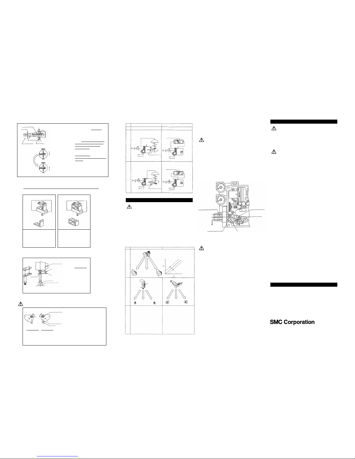
5.1 Electrical wiring
Connect the (+) and (-) output terminal of positioner with the (+) and (-)
input terminal of positioner respectively. The input port of the electrical
connection is equiped with a (blue) cable connector M20 x 1.5.
WARNING
To use as explosion protection specification may only be connected to
a certified intrinsically safe electrical circuit with the following maximum
values and connected to earth.
Parameters (current circuit)
Ui ≤ 28V, Ii ≤ 125mA, Pi ≤ 1.2W, Ci ≤ 0nF, Li ≤ 0mH
Table 2
5 ADJUSTMENT
CAUTION
Check the following prior to start the adjustment.
(1) Check that the pipeline is correctly connected with the pressure
supply port and OUT1 and OUT2 ports.
(2) Check that the actuator and positioner are sturdily connected.
(3) Check that the span adjusting lever of internal feed back (Type
IP6000) is attached to the correct (normal or reverse) position.
(Refer to Tables 2.)
(4) Check for locking of the auto/manual changeover screw of pilot
valve (fully tightened in the clockwise direction).
(5) Check for correct use of the cam face (normal or reverse) in Type
IP6100 and that the flange nut is firmly locked. (Refer to Table 2.)
(6) Check that the wires are connected correctly with the (+), (-) and
grounding terminals.
6 MAINTENANCE
WARNING
(1) After installation, repair and disassembly, connect compressed air
and perform a proper function test and leak test. If bleed noise is
louder than the initial state, or operation is abnormal, stop operation
and check if installation is correct or not.
(2) Modification of Electrical construction is prohibited to maintain
explosion proof certification.
CAUTION
(1) Check if supply air is clean or not. Inspect compressed air cleaning
system periodically so that dust, oil and humidity, which can cause
malfunction and failure of the unit, do not enter the equipment
(2) If handled improperly, compressed air can be dangerous.
Maintenance and replacement of unit parts should only be
performed by trained and experienced personnel for
instrumentation equipment , as well as following the product
specifications.
(3) Check the positioner once a year. When an excessively worn
diaphragm, O-ring or other packing of any unit that has been
damaged is found, replace with new ones. Treatment at an early
stage is especially important if the positioner is used in a place of
severe environment, such as costal areas.
(4) Before removing the positioner for maintenance, or replacing unit
parts after installation, ensure the supply pressure is shut off and all
residual air pressure is released from the piping.
(5) When the fixed orifice is clogged with carbon particles or other
material, remove the pilot valve Auto/Manual change over screw
(built in fixed aperture) and clean it by inserting a 0.3mm diameter
wire into the aperture.
(6) When you disassemble the pilot valve, coat the O-ring of the sliding
section with grease. (Use the TORAY SILICONE SH45 grease.)
(7) Check for air leaks from the compressed air piping. Air leaks could
lower the performance characteristics of the positioner. Air is
normally discharged form a bleed port, but this is necessary air
consumption based on the construction of the positioner, and is not
an abnormality if the air consumption is within the specified range.
Fig.7 Example of attaching
using the positioner back
screw
Attaching using the screw hole at
the positioner back and the
screw hole at the actuator top.
Fig.6 Example of attaching
using the positioner side
screw
Attaching using the screw hole of
a side of the positioner and the
screw hole at the actuator top.
(1) Use the DA face of the cam to turn the actuator main
shaft clockwise (viewed from the positioner front cover
side) at the time of input signal increase. Use the RA
face to turn it counter-clockwise (reverse actuation).
Correctly attach the cam to the flange part of feed back
shaft.
(2) Attach the cam in the procedure of loosening the
hexagonal nut with flange first, setting the using
actuatorto the starting position and then setting the
cam reference line and the bearing contact point of
span adjusting arm unit to the matching position.
(3) Do not apply the supply pressure when attaching the cam as otherwise it is very dangerous.
(4) When the positioner is shipped out of our plant, the cam is tentatively tightened to the shaft.
Be sure to firmly lock the cam to the lock nut [tightening torque 2.0 ~ 2.5 Nm.
(1) Attach to the position at which
the positioner feed back shaft
and the rotary actuator main
shaft are almost concentric
(range in which the spring pin
of feed back shaft edge enters
the hole of fork lever assembly
shaft edge).
(2) If the seration joint type for
IP6100 is made in a special
specification, it can be used
for this connection.
Counterclockwise
(Reverse actuation)
Clockwise
Cam reference
Bearing
(Normal actuation)
Hex. nut with flange
(1) Attach to the position that the valve
stem and lever form the right angle
when the input signal is 50% (distribute
evenly with 50% input signal set as the
reference).
(2) Attach to the position of the runout
angle is within the range of 10° to 30°.
(3) To move the valve stem downward at
the time of input current increase
(normal actuation), attach to the position
at which the tightening spring comes to
the upper side of the connecting metal,
as shown in Fig 11.
To move the valve stem upward (reverse
actuation), turn-over the feedback lever
and attach to the position at which the
tightening spring comes to the lower
side of connecting metal.
Tighening spring
Right angle
Input 0% (or 100%) position current
Input 100% (or 0%) position current
Input 50% position current
Connecting metal
Valve stem
Positioner body
Fedd back
lever
(The stem moves down as the input increases)
Stem direction
Stem direction
Turn over the
feed back lever
Fig.4 Attaching the feed back lever
OUT1
OUT2
Bracket shape
example
Bracket shape
example
OUT1
OUT2
Fork lever assembly
(P368010-36)
Positionery body
Fork pin unit
(P368010)
M6 x 1
Actuator main shaft
Spring pin
Fig.8 Attaching the feed back lever
Single action
Reverse actuation Normal actuation
Double action
IP6000 (Lever type)
IP6100 (Rotary type)
Actuation: The stem moves in the arrow
direction when the input current increases.
Actuation: The actuator main shaft turns
clockwise when the input signal increases.
Actuation: The stem moves in the arrow
direction when the input current increases.
(Reverse actuation using the normal actuation drive unit).
Actuation: The actuator main shaft turns
counter-clockwise when the input signal
increases.
OUT 1
Span adjusting lever
normal position
IN
SUP
IN
IN
IN
OUT 1
Main shaft
Double action
actuator
The cam
should be
set to DA
surface.
Double action
actuator
Main shaft
The cam
should be
set to RA
surface.
OUT 2
OUT 1
OUT 2
OUT 2
Span adjusting lever
normal position
SUP
Span adjustment Zero point adjustment
Type IP6000
Zero adjusting knob
Move
clockwise
Move counterclockwise
When the zero adjusting knob is turned clockwise, the starting point increases. When it is
turned counter-clockwise, the starting point
decreases.
Stroke
Input current
Decrease of starting points
Increase of
starting points
Counterclockwise
turn
Adjusting producre
(1) Set the input current to 0% (4mADC in the standard
specification) and turn the zero adjusting knob by
hand to set it to the actuator starting point.
(2) Then set the input current to 100% (20mADC in the
standard specification) and check the actuator stroke.
At this point depending on the span is too large or too
small, loosen the lock screw and adjust the span as
shown in the illustration above.
(3) Set the input current to 0% and conduct the zero
point adjudtment, as done in Step (1) again.
(4) Repeat the above operations until the predetermined
stroke of the actuator is obtained to the input current.
Too small starting point
Starting point OK
Too large starting point
to span adjustment
Span adjusting
screw
Lock screw
Span adjusting
screw
Move clockwise
Move counter-clockwise
Too large span
Spam OK
Too small span
Too large span
Spam OK
Too small span
Move counter-clockwise
Move clockwise
Type IP6100
(blue) cable connector
M20 x 1.5
Input current
Mini-terminal unit
Twisted wire fixing screw
M4 screw for internal
grounding terminal connection
Solderless terminal
(Use twisted wire of 0.3 to 1.65mm²)
Grounding
(Use twisted wire of
0.5 to 1.5mm²)
*¹
*²
Fig.5 Use position for feedback lever
Fig.9 Example of cam attaching
IP60X14-TFH11GB-C
7 CONTACTS
AUSTRIA (43) 2262 62280 NETHERLANDS (31) 20 531 8888
BELGIUM (32) 3 355 1464 NORWAY (47) 67 12 90 20
CZECH REP. (420) 541 424 611 POLAND (48) 22 211 9600
DENMARK (45) 7025 2900 PORTUGAL (351) 21 471 1880
FINLAND (358) 207 513513 SLOVAKIA (421) 2 444 56725
FRANCE (33) 1 6476 1000 SLOVENIA (386) 73 885 412
GERMANY (49) 6103 4020 SPAIN (34) 945 184 100
GREECE (30) 210 271 7265 SWEDEN (46) 8 603 1200
HUNGARY (36) 23 511 390 SWITZERLAND (41) 52 396 3131
IRELAND (353) 1 403 9000 UNITED KINGDOM (44) 1908 563 888
ITALY
(39) 02 92711
URL http://www.smcworld.com (Global) http://www.smceu.com (Europe)
Specifications are subject to change without prior notice from the
manufacturer.
© SMC Corporation All Rights Reserved.
 Loading...