

SMC Networks INR-244-749, INR-244-745, INR-244-746, INR-244-736, INR-244-747 Operation Manual
...
HEC-OM-O018-A
June 2012
Operation Manual
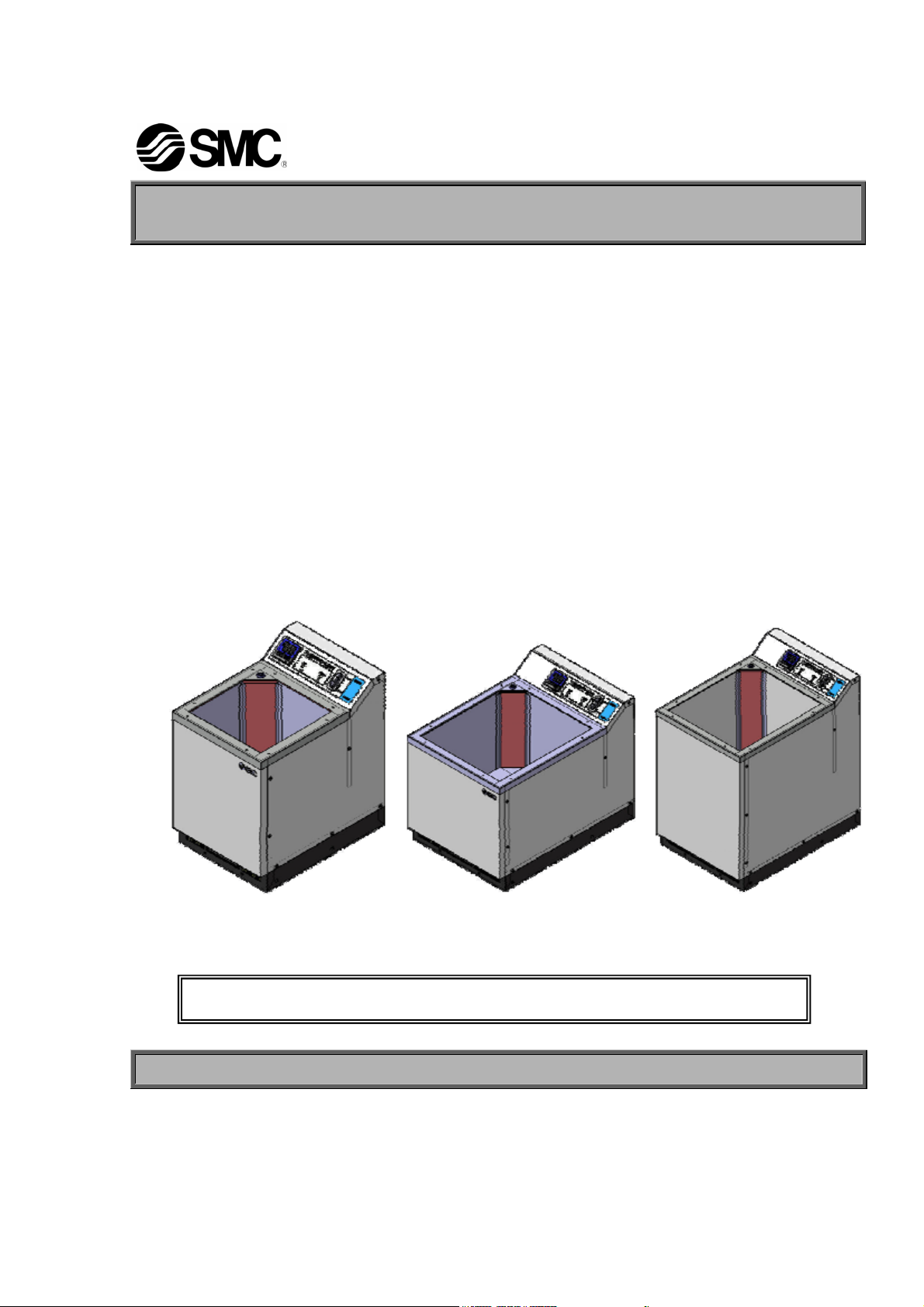
Thermo Electric Bath
Model No. INR-244-733
INR-244-736
INR-244-745
INR-244-747
Copying, duplicating or transferring any part or the entirety of this manual without the
prior permission of SMC is strictly prohibited.
INR-244-734
INR-244-746
INR-244-748
INR-244-749
。
INR-244-749
Keep this manual available whenever necessary.
© 2012 SMC CORPORATION All Rights Reserved
To the customers
Thank you for purchasing our Thermo Electric Bath (hereinafter called “product”).SMC always strives to
provide the highest quality high-performance temperature control devices to our customers by utilizing
our original technology.
For the long-term and safe use of this product, be sure to read and understand this Operating Manual
(hereinafter called “this manual”) thoroughly before use. Also, keep this manual available whenever
necessary.
1) When the product is received, check the contents of the package immediately.
Packaging content
Item Qty.
1 Thermo Electric Bath 1 pc
2 Operation Manual 1 pc
2) Observe the warnings and precautions defined in this manual.
3) This manual provides explanations of the installation and operation of this product. Only those who
have a thorough understanding of the operating procedures and who have basic knowledge and skills
in handling industrial equipment are qualified to perform installation and operation.
4) The contents of this manual and the related documents supplied with this product shall be neither
regarded as a provision of the contract nor utilized to correct or modify the existing agreements,
commitments and relations.
5) Copying, duplicating or transferring any part or the entirety of this manual without the prior permission
of SMC is strictly prohibited.
6) The product is designed for use of industrial applications and research facilities of science. When it is
used for applications that require the consideration additional safety precautions, e.g., for medical
devices, investigate the safety needs for the application at the customer’s site before use.
<Contact>
If you have any questions or are unclear about any of the content of this manual, please contact the
following department.
SMC Corporation R&D Center
Product Development Division-6
Address: 4-2-2 Kinunodai, Tsukubamirai-shi Ibaraki, 300-2493, Japan
E-mail: kaihatsu_6_g3@.smcjpn.co.jp
Note: The contents of this manual are subject to change without notice.

HEC-OM-O018-A
Table of Contents
Table of Contents
Chapter 1 Safety Instructions ............................................................... 1-1
1.1 Dangers, Warnings, and Cautions Used in This Manual .......................................1-1
1.1.1 Hazard Levels ..................................................................................................................... 1-1
1.1.2 Definitions of “Serious injury” and “Minor injury” ................................................................. 1-2
1.1.3 Symbols............................................................................................................................... 1-2
1.2 Hazard Warning Labels............................................................................................. 1-4
1.2.1 Content of label ................................................................................................................... 1-4
1.2.2 Location of hazard warning label ........................................................................................ 1-5
1.3 Location of Model Label ...........................................................................................1-5
1.4 Safety Measures ........................................................................................................1-6
1.4.1 Precautions ......................................................................................................................... 1-6
1.4.2 Protective Equipment .......................................................................................................... 1-7
1.4.3 Long-term Storage...............................................................................................................1-7
1.4.4 Disposing of Product ........................................................................................................... 1-7
1.5 Safety Interlocks........................................................................................................ 1-8
Chapter 2 Description and Function of Each Part .............................. 2-1
Chapter 3 Transporting and Installation .............................................. 3-1
3.1 Transporting .............................................................................................................. 3-1
3.2 Installation..................................................................................................................3-2
3.2.1 Installation Conditions .........................................................................................................3-2
3.2.2 Installation in Clean Room .................................................................................................. 3-3
3.2.3 Pollution Degree.................................................................................................................. 3-4
3.2.4 Installation of Brackets ........................................................................................................3-4
3.3 Wiring .........................................................................................................................3-5
3.3.1 Power Sourse Specification ................................................................................................ 3-5
3.3.2 Power Supply Cable and Connector................................................................................... 3-5
3.3.3 Connector for External Equipment ...................................................................................... 3-6
3.3.4 Procedures for wiring instllation .......................................................................................... 3-7
3.4 Installation of Facility Water Piping .........................................................................3-8
Chapter 4 System Set-up....................................................................... 4-1
4.1 Pre-check ................................................................................................................... 4-1
4.2 Facility Water .............................................................................................................4-1
4.2.1 Reference of water quality .................................................................................................. 4-1
4.2.2 Facility water run through.................................................................................................... 4-2
4.3 Filling Bath liquid ......................................................................................................4-2
4.3.1 Preparation of Bath Liquid................................................................................................... 4-2
4.3.2 Filling Bath Liquid ................................................................................................................ 4-4
TOC-1

HEC-OM-O018-A
Table of Contents
4.4 Turning ON power .....................................................................................................4-5
4.5 Setting of Values ....................................................................................................... 4-5
4.6 Cautions for Operation Control ...............................................................................4-7
Chapter 5 Operation .............................................................................. 5-1
5.1 Operation of Controller............................................................................................. 5-1
5.1.1 Details of Controller .............................................................................................................5-1
5.1.2 Setting of Data ..................................................................................................................... 5-2
5.1.3 Selection of Operation Mode ............................................................................................... 5-3
5.1.4 Details of Operation Mode................................................................................................... 5-4
5.1.5 Selection of Setting Mode.................................................................................................... 5-6
5.1.6 Selection of Initial Setting Mode .......................................................................................... 5-7
5.1.7 Details of Initial Setting Mode ..............................................................................................5-7
5.1.8 Selection of Control Setting Mode ....................................................................................... 5-8
5.1.9 Details of Control Setting Mode........................................................................................... 5-9
5.1.10 Selection of Communication Setting Mode........................................................................ 5-11
5.1.11 Details of Communication Setting Mode ........................................................................... 5-11
5.1.12 Initial Value and Setting Range for Each Mode .................................................................5-13
5.2 Alarms ...................................................................................................................... 5-14
5.2.1 Content of Alarms .............................................................................................................. 5-14
5.2.2 Troubleshooting .................................................................................................................5-15
Chapter 6 Maintenance.......................................................................... 6-1
6.1 Regular Maintenance ................................................................................................ 6-1
6.1.1 Draining the Bath liquid........................................................................................................6-2
6.1.2 Check strainer and clean the bath....................................................................................... 6-2
6.1.3 Check liquid surface waving ................................................................................................6-2
6.2 Before returning the product ...................................................................................6-3
Chapter 7 Appendix ............................................................................... 7-1
7.1 Outline Dimensions................................................................................................... 7-1
7.1.1 INR-244-733/-736/-745/-747 ...............................................................................................7-1
7.1.2 INR-244-734/-746................................................................................................................7-2
7.1.3 INR-244-748/-749................................................................................................................7-3
7.2 Specifications ............................................................................................................ 7-4
7.3 Performance Chart ....................................................................................................7-6
7.3.1 Cooling Capacity.................................................................................................................. 7-6
7.3.2 Heating Capacity .................................................................................................................7-6
7.3.3 Facility Water Pressure Loss............................................................................................... 7-7
Chapter 8 Warranty................................................................................ 8-1
8.1 Limited warranty and Disclaimer/Compliance Requirements............................... 8-1
8.2 Compliance Requirements .......................................................................................8-2
TOC-2
Chapter 1 Safety Instructions
Chapter 1 Safety Instructions
HEC-OM-O018-A
Be sure to thoroughly read and understand the important precautions
defined in this manual before using this product.
1.1 Dangers, Warnings, and Cautions Used in This
Manual
1.1.1 Hazard Levels
These safety instructions are intended to prevent hazardous
situations and/or equipment damage.
These instructions indicate the level of potential hazard with the labels
of “Caution,” “Warning” or “Danger.”
They are all important notes for safety and must be followed in
addition to International Standards (ISO/IEC)
regulations.
*1) IEC 60204-1: Safety of machinery -- Electrical equipment of machines
(Part 1: General requirements)
ISO 10218-1: Manipulating industrial robots -Safety.
etc.
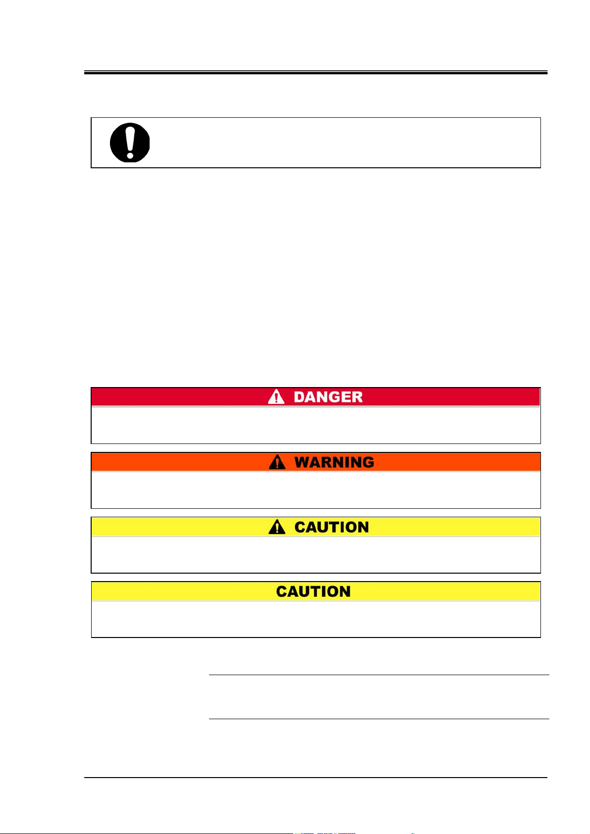
"DANGER" denotes that there is an imminent hazard which, if not avoided, will
cause death or serious injury during operation.
*1), and other safety
"WARNING" indicates a hazard with a medium level of risk which, if not avoided,
could result in death or serious injury.
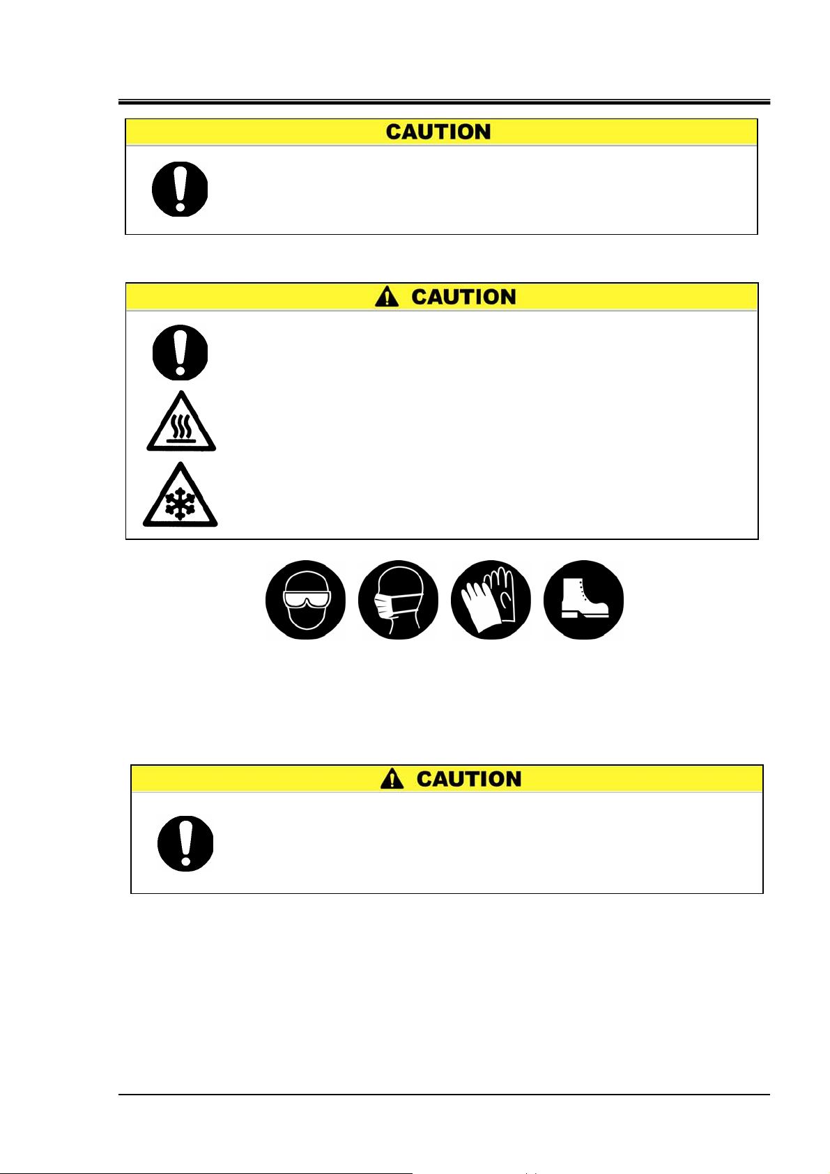
"CAUTION" indicates a hazard with a low level of risk which, if not avoided, could
result in minor or moderate injury.
"CAUTION" without an exclamation point denotes that there is a hazard which, if not
avoided, may cause damage to or the failure of the system, facility, or devices.
[Tips]
Tips are provided when there is information and content that personnel are
required to be aware of and refer to for product operation and maintenance of
this product.
1.1 Dangers, Warnings, and Cautions Used in This Manual
1-1
HEC-OM-O018-A
Chapter 1 Safety Instructions
1.1.2 Definitions of “Serious injury” and “Minor injury”
“Serious injury”
This term describes injuries such as the loss of eyesight, wounds, burns,
frostbite, electric shock, fractures, and toxicity that leave aftereffects, and/or
injury requiring hospitalization and/or a prolonged stay in a hospital.
“Minor injury”
This term describes injuries that do not require hospitalization or a
prolonged stay in a hospital (injuries other than the “serious injuries”
described above).
1.1.3 Symbols
This manual provides the following symbols in addition to “Danger”,
“Warning”, and “Caution” to present warning details in an
easy-to-understand manner.
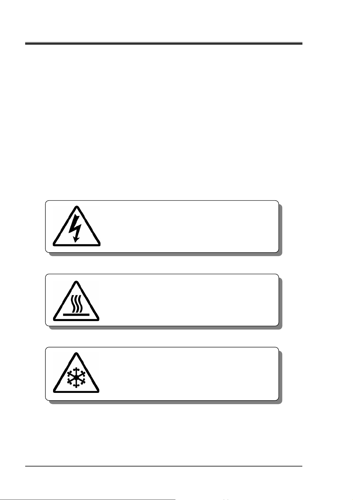
Symbol of electrical hazard
This symbol warns you of potential electrical shock.
Symbol of heat hazard
This symbol warns you of potential burns.
Symbol of low temperature hazard
This symbol warns you of potential frostbite.
1.1 Dangers, Warnings, and Cautions Used in This Manual
1-2
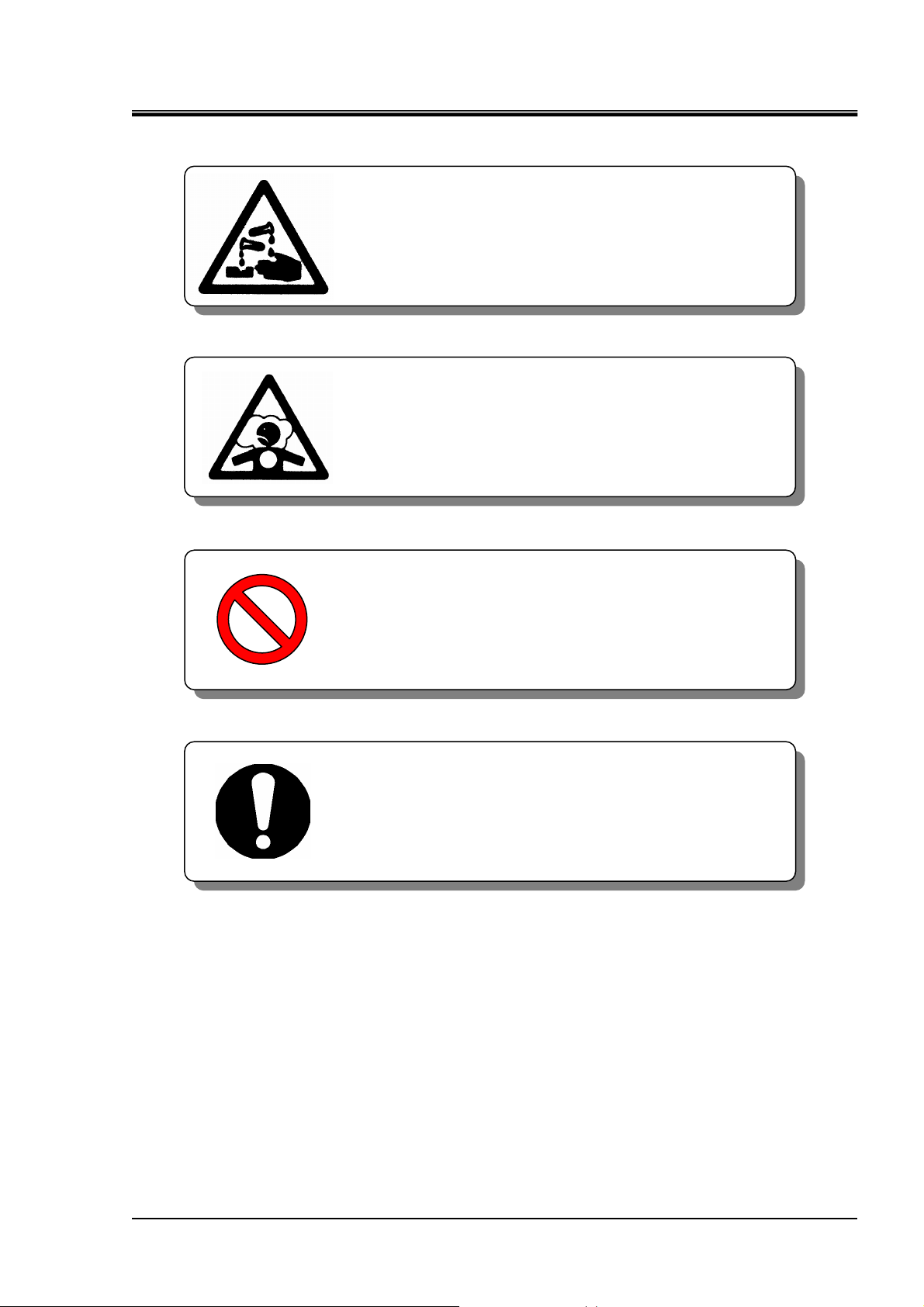
Symbol for corrosion
Symbol for inhalation
“Don’t” Symbol
Chapter 1 Safety Instructions
This symbol warns of chemical corrosion. When
handling chemical fluids, read the MSDS carefully
and use appropriate protective equipment.
This symbol warns of chemical inhalation. When
handling chemical fluids, read the MSDS carefully
and use appropriate protective equipment.
HEC-OM-O018-A
“Do” Symbol
This symbol denotes actions which you must not
perform in the operation of this product.
This symbol denotes actions which you must
perform and items you must observe in the
operation of this product.
1.1 Dangers, Warnings, and Cautions Used in This Manual
1-3
HEC-OM-O018-A
Chapter 1 Safety Instructions
1.2 Hazard Warning Labels
Hazard warning labels are applied to the sections of this system in which
potential hazards are present during system operation and maintenance.
Hazard warning labels are presented in sizes and colors that will get the
attention of the worker. They contain symbols in addition to the descriptions
of warnings.
z Do not peel off or deface the Warning label and Caution label.
z Confirm the location of the Warning label and Caution label.
z Read the contents of the Warning label and Caution label carefully
z Users are NOT allowed to change the location of the Warning label
and keep them in mind.
and Caution label. If replacing a peeled off or worn out label, affix
the new label to exactly the same location as the replaced label.
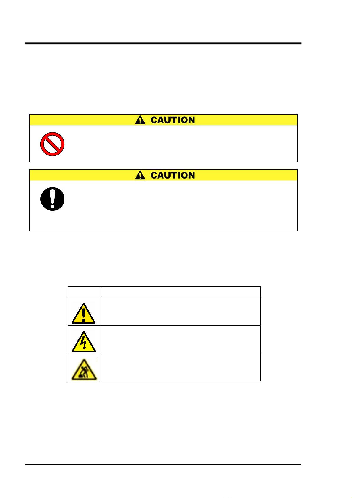
1.2.1 Content of label
Symbol Meaning
Table 1-1 Content of Caution label
Attention, consider accompanying documents.
Caution, risk of electric shock.
1.2 Hazard Warning Labels
Caution, handling of heavy object may affect human body.
It should be handled by two or more workers.
1-4
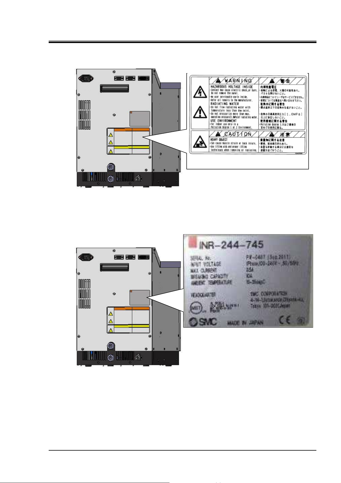
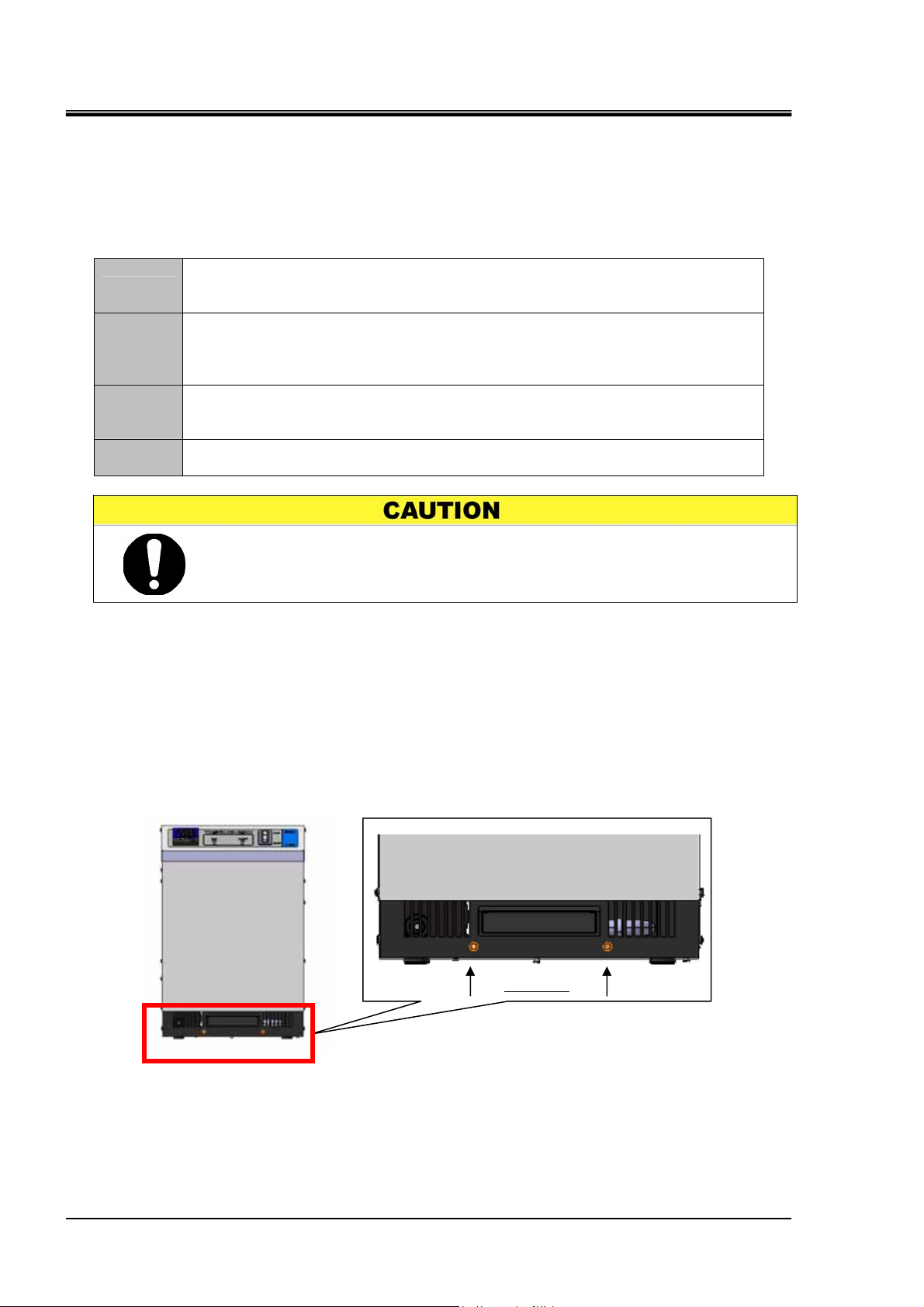
1.2.2 Location of hazard warning label
HEC-OM-O018-A
Chapter 1 Safety Instructions
Fig. 1-1 Location of hazard warning label.
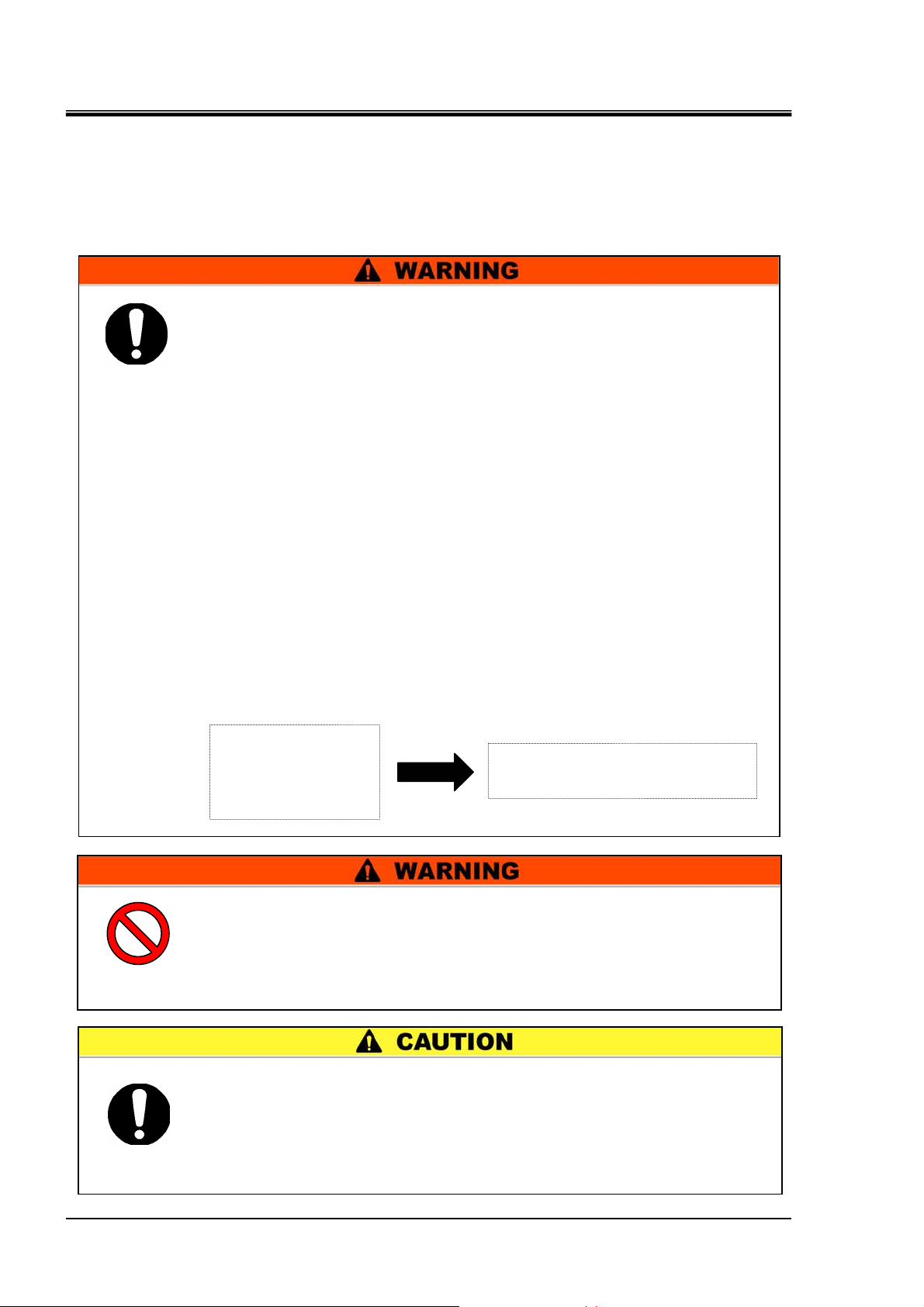
1.3 Location of Model Label
Warning label
Fig. 1-2
Location of Model Label
1.3 Location of Model Label
1-5
HEC-OM-O018-A
Chapter 1 Safety Instructions
1.4 Safety Measures
1.4.1 Precautions
This product is designed with consideration for safety. However, misuse
may result in electrical shock or other accidents.
z The compatibility of the product is the responsibility of the person
z Be sure that you understand how the chemical fluids use in this
z Read the precautions described in this manual carefully and keep
z Stop operation immediately after any abnormal occurrence.
Be sure to keep the following instructions in mind to prevent accidents.
who designs the equipment or decides its specifications.
Since the product specified here is used under various operating conditions,
its compatibility with specific equipment must be decided by the person who
designs the equipment or decides its specifications based on necessary
analysis and test results.
The expected performance and safety assurance of the equipment will be the
responsibility of the person who has determined its compatibility with the
product.
This person should also continuously review all specifications of the product
referring to its latest catalog information, with a view to giving due
consideration to any possibility of equipment failure when configuring the
equipment.
product affect the human body. Follow the MSDS when handling
chemical fluids.
them strictly.
If an abnormality (noise, odor, smoke, water leakage, etc.) occurs,
stop this product (cutoff the power supply).
Abnormal noise,
odor, smoke or
water leakage
occurs;
1) Cutoff power supply
2) Request repair
z Do not disassemble or retrofit this product.
The internal parts of this product cannot be retrofitted by the user.
Contact the sales distributor or branch for all repairs. The user must
not perform any repairs. A product repaired by the user cannot be
guaranteed and carries the danger of causing electrical shock and
z The product is provided for use in manufacturing industries.
The product herein described is basically provided for peaceful use in
manufacturing industries.
If considering using the product in other industries, consult SMC
beforehand and exchange specifications or a contract if necessary.
If anything is unclear, contact your nearest sales branch.
1.4 Safety Measures
1-6
z Keep within the margin of safety in relation to cooling and heating
z When restarting the power supply, wait 3 sec or more after the
capacity.
indications on the display light off.
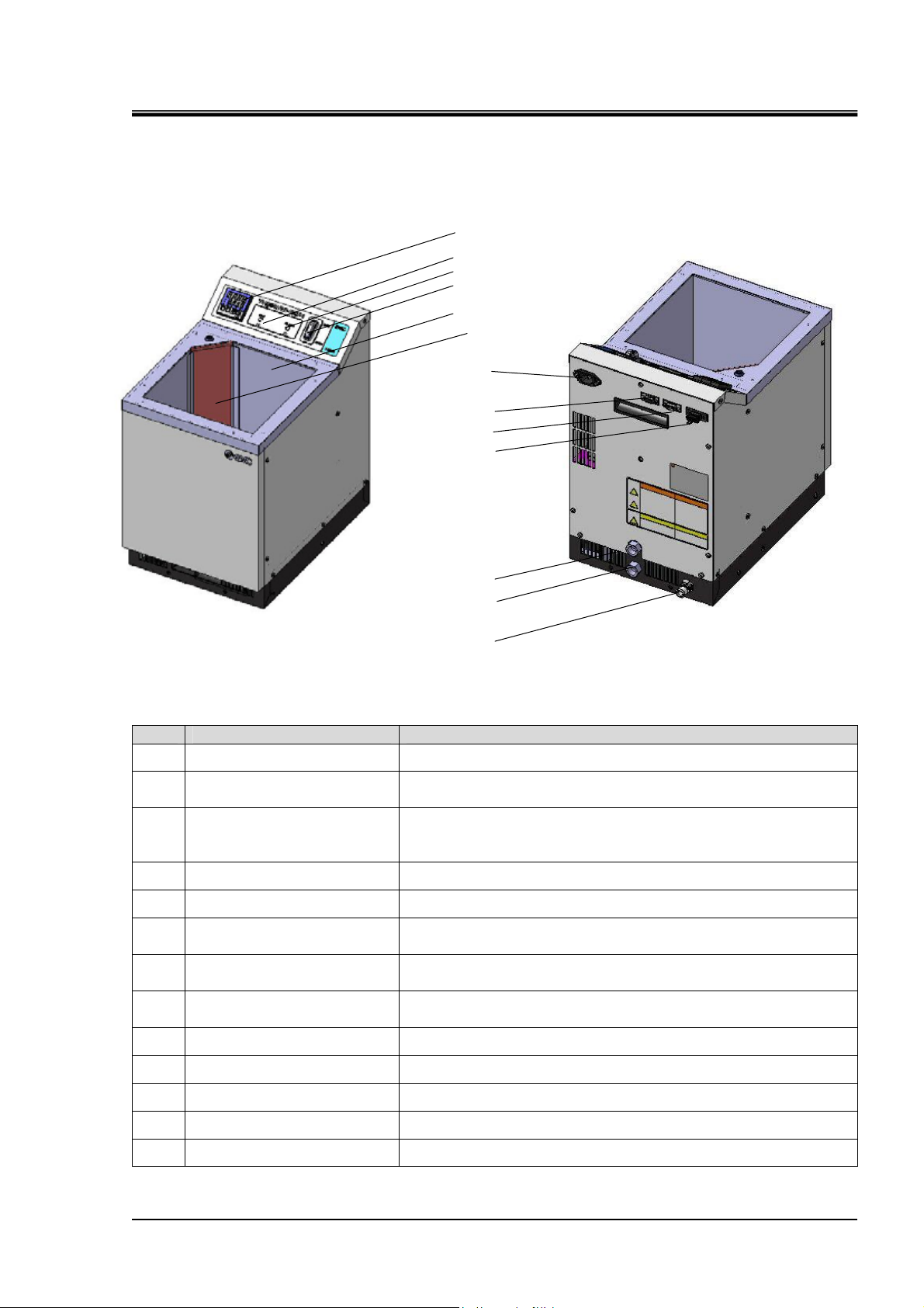
1.4.2 Protective Equipment
HEC-OM-O018-A
Chapter 1 Safety Instructions
z Wear protective equipment in order to maintain safety when
z Touching the bath liquid and inner surface of the liquid bath may
installing and/or handling the product.
When handling chemicals for the product especially, note the
contents of the MSDS and wear protective goggles, gloves, and a
mask.
cause burns or frostbite depending on the temperature set for this
product. Be sure to use heat (cold) resistant gloves when handling
this product.
Protective
goggles
Mask Gloves Safety
shoes
Fig. 1-3 Protective equipment
1.4.3 Long-term Storage
z Turn OFF main power switch and remove all cables and piping
z Completely empty the bath liquid from the liquid bath. Also, do not
from the product.
allow foreign matter to enter the inside of the bath.
z Drain facility water from the facility water connection.
1.4.4 Disposing of Product
When disposing of this product, be sure to use an industrial waste
processing vendor that conforms to the “Law concerning disposal of waste
and cleaning” and the “Ordinance defined by each municipal corporation”.
Dispose of the Bath liquid in the manner described in the MSDS.
1.4 Safety Measures
1-7

HEC-OM-O018-A
Chapter 1 Safety Instructions
1.5 Safety Interlocks
For safe use, this product has the following interlocks.
*Before reset interlocks, be sure to search and remove cause of interlocks.
Table 1-2 Safety Interlocks List
No. Content Installation part
Status of product after
interlock works
How to reset*
1 Over current
2
Overheat of heat
exchanger
3
Main power switch
(Circuit protector)
Bath liquid side of
the heat exchanger
Facility water side
of the heat
exchanger
Cut of all AC power.
Temperature control is
stopped.
ALARM LED (red) lights
up.
Turn OFF Main power
switch once.
Then, Turn ON Main
power switch again.
(Restart the product)
1.5 Safety Interlocks
1-8
HEC-OM-O018-A
Chapter 2 Description and Function of Each Part
Chapter 2 Description and Function of
Each Part
Fig. 2 Thermo Electric Bath
Table 2 Thermo Electric Bath
No. Description Function
Contoroller Various displays are shown and settings are input.
①
Main power switch
②
(Circuit protector)
ALARM LED(Red)
③
RUN LED(Green)
④
Main power ON/OFF of product.
Lights up when an alarm occurred.
For details, refer to page 5-14 “5.2.1 Content of Alarms”,
Table5-3.
Lights up while the product is running.
①
④
③
②
⑤
⑫
⑥
⑦
⑧
⑬
⑨
⑩
⑪
Bath Vessel to store the bath liquid.
⑤
Power supply connector
⑥
(AC)
Communication connector
⑦
(COMMUNICATION)
Alarm output connector
⑧
(ALARM)
Facility Water outlet port Facility water outlet port, connection size is Rc3/8.
⑨
Facility Water inlet port Facility Water inlet port, connection size is Rc3/8.
⑩
Drain port CPC coupling PLCD 16004
⑪
Strainer Prevents clogging the pump suction port.
⑫
Level switch connector Use to connect level switch (Option)
⑬
IEC 60320 C14 connector.
Connector for RS-485(-733/-734/-736/-748) or
RS-232C(-745/-746/-747/-749) serial communication.
Connector for contact signals for alarms.
For details, refer to page5-14 Content of Alarms”, Table5-3.
1.5 Safety Interlocks
2-1

HEC-OM-O018-A
Chapter 3 Transporting and Installation
Chapter 3 Transporting and Installation
3.1 Transporting
z Do not service or attempt to remove product and
z Contact SMC beforehand and take special consideration of safety
machinery/equipment until safety is confirmed.
1.The inspection and maintenance of machinery/equipment should only be
performed after measures to runaway of the driven objects have been
confirmed.
2.When the product is to be removed, confirm that the safety measures as
mentioned above are implemented and the power from any appropriate
source is cut, and read and understand the specific product precautions of all
relevant products carefully.
3.Before machinery/equipment is restarted, take measures to prevent
unexpected operation and malfunction.
measures if the product is to be used in any of the following
conditions.
1.Conditions and environments outside of the given specifications, or use
outdoors or in a place exposed to direct sunlight.
2.Installation on equipment in conjunction with atomic energy, railways, air
navigation, space, shipping,vehicles, military, medical treatment, combustion
and recreation, or equipment in contact with food and beverages, emergency
stop circuits, safety equipment or other applications unsuitable for the
standard specifications described in the product catalog.
3.An application which could have negative effects on people, property, or
animals requiring special safety analysis.
z Proper procedure must be followed when using this product.
z Only personnel with appropriate training should operate machinery
Exercise caution to assure personal safety during the installation,
transporting operation, maintenance, and inspection of the system.
and equipment.
The product specified here may become unsafe if handled incorrectly.
The assembly, operation and maintenance of machines or equipment
including our products must be performed by an operator who is appropriately
trained and experienced.
z Be sure to transport using a packaging box specific to this product.
3.1 Transporting
3-1
HEC-OM-O018-A
jury
Chapter 3 Transporting and Installation
z Avoid strong vibrations and impacts
This product is precision equipment and must not be subject to strong
vibration and impact during transport.
3.2 Installation
3.2.1 Installation Conditions
z Keep enough open space to access main power switch and any
z Keep enough ventilation for liquid vapor.
z This product should be installed on a vibration-free stable level
z The mounting orientation of this product is horizontal.
z Place the product in a flat area which can handle its weight and
cable connections.
place.
take measures to prevent the tipping of the product. If installed
improperly, the product might leak liquid or topple, resulting in
in
.
z Do not use this product in the following environments, where the
product may not work normally and may be damaged.
Outdoor
z
Altitude higher than 2000m.
z
Environments containing splashing water, salt water, oil, or various
z
chemicals (including chemical mists).
Environments containing particles and dust.
z
Environments containing corrosive gas, solvents and flammable gas.
z
Envirnoments containing direct sunlight and radiant heat.
z
Environments having ambient temperatures over the following range:
z
Operation 10 to 35
Storage 0 to 50
circuit.)
Environments having ambient humidity over the following range:
z
Operation 35 to 80%
o
C
o
C (with no liquid in the bath and facility water
Storage 35 to 85%
3.2 Installation
3-2

HEC-OM-O018-A
Chapter 3 Transporting and Installation
Environments with sharp temperature changes.
z
Environments generating strong magnetic noise (having a strong
z
electric or magnetic field that generates surges).
Environments generating electrical static discharge and conditions in
z
which static electricity is applied to this product.
Environments generating strong high frequency radiation (including
z
radio frequency appliances such as mobile phones and tranceivers).
Environments generating strong vibrations and impacts.
z
Environments that may be damaged by lightning.
z
Environments in which forces or gravity may deform the body of the
z
product.
Environments containing harmful gases such as silicone.
z
Locating the cables of the product near the power lines of other
z
machines.
Conditions in which insufficient grounding for the power supply is
z
provided
Conditions that cause dew condensation (this may occur on the surface
z
of the piping when the Facility Water temperature is low).
Places not allowing a space of 50mm or more at the air inlet of the
z
Surroundings of product and thus causing the sucking of exhausted
heat from the air inlet.
Places preventing the horizontal set-up of the product.
z
3.2.2 Installation in Clean Room
This product uses a fan and generates dust. When it is set up and operated
in a clean room, take appropriate preliminary measures for dust.
3.2 Installation
3-3
HEC-OM-O018-A
Chapter 3 Transporting and Installation
3.2.3 Pollution Degree
The pollution degree is a classification from 1 to 4 degrees depending on
the pollution present in the air. This product is suitable for environments with
a pollution degree of 1 or 2.
Table 3-1 Pollution degree classification
There is no pollution or only dry and nonconductive pollution occurs.
Degree 1
Degree 2
Degree 3
Degree 4
An example of an environment of this degree is a clean room or a place using an
air cleaner.
Normally, only nonconductive pollution occurs. The pollution may become
conductive temporarily because of dew condensation.
An example of an environment of this degree is a place where electric equipment
can operate normally, such as a working office or a control panel.
Conductive pollution or dry and nonconductive pollution which can become
conductive when dew condensation occurs. An example of an environment of this
degree is a factory.
Conductive pollution that holds its conductivity due to conductive dust, rain or
snow. An example of an environment of this degree is the outdoors.
z This product can be used in environments with pollution degree 1
or 2.
3.2.4 Installation of Brackets
If tie-down needed, please use the M4 screws which are located in the
z
front and back of this product. The screw must not enter by 30mm or
more in the product.
Refer to page7-1 “Outline Dimensions”.
z
Close-up
Fig. 3-1 Screws for tie-down
3.2 Installation
3-4
3.3 Wiring
z Only qualified personal are allowed to install wiring.
z Be sure to turn OFF the power prior to wiring to assure safety.
z The system wiring requires not only a through connection with the
z Be sure to supply the power to this product according to the
z Always establish a connection to a ground for safety.
z Be sure that no ground connection is made to a water pipe, gas pipe
HEC-OM-O018-A
Chapter 3 Transporting and Installation
Do not do any wiring when the system is energized.
designated cable but also securing to prevent loose connection.
Poor connection and securing may cause electric shock, heat spots,
fire, or communication errors.
specification.
and lighting rod.
z Be sure to provide protective ground. IEC protection
class of the product is class I. Be sure to provide protective
ground (ground resistance of 100Ω or less). Grounding can be
provided via the PE line of the power supply cable. For details
of the power supply cable, refer to page 3-5, Power Supply
Cable and Connector
z Do not use the same ground being used by equipment
that generates strong electrical magnetic noise or high
3.3.1 Power Sourse Specification
Confirm that the power supply at your workplace has sufficient capacity and
a voltage within that specified. It is recommended to install ground-fault
circuit interrupter. Rated leakage current:30mA or less.
Table 3-2 Electrical specifications of power supply
Model Number Voltage Rated Current
INR-244-733/-745 3.5A(at 100VAC)~1.5A (at 240VAC)
INR-244-734/-736/-746/
-747/-748/-749
Single Phase
100VAC~240VAC+/-10%
(Over Voltage Category
I or II)
5.5A(at 100VAC)~2.5A (at 240VAC)
3.3.2 Power Supply Cable and Connector
The power cable and connecter are to be prepared under your responsibility,
referring to the following table.
Power supply Cable
Table 3-3 Power Supply Cable and Connector
Cable and Connector Types (for your system)
Cable 3 wires, thicker than 14AWG, includes ground.
Power Supply Connector
IEC60320 C-13 equivalent
10A cable mount female connector
3.3 Wiring
3-5
 Loading...