

SMC Networks IN574-95 Installation & Maintenance Manual
4 Operation details
3 Wiring
(1) (2)
I
nstallation & Maintenance Manual
Simple speed meter (Request for Special)
For pneumatic cylinder with built-in magnet (round groove)
IN574-95
IN574-TFT04
1
Safety Instructions
This manual contains essential information for the protection of users
and others from possible injury and/or equipment damage.
•Read this manual before using the product, to ensure correct handling,
and read the manuals of related apparatus before use.
•Keep this manual in a safe place for future reference.
•These instructions indicate the level of potential hazard by label of
"Caution", "Warning" or "Danger", followed by important safety
information which must be carefully followed.
•To ensure safety of personnel and equipment the safety instructions in
this manual and the product catalogue must be observed, along with
other relevant safety practices.
CAUTION indicates a hazard with a low level of risk
which, if not avoided, could result in minor or
moderate injury.
Caution
Warning
Danger
WARNING indicates a hazard with a medium level
of risk which, if not avoided, could result in death or
serious injury.
DANGER indicates a hazard with a high level of risk
which, if not avoided, will result in death or serious
injury.
This product is class A equipment that is intended for use in an industrial
environment.
There may be potential difficulties in ensuring electromagnetic
compatibility in other environments due to conducted as well as radiated
disturbances.
■
Handling Precautions
○Follow the instructions given below for selection and handling.
Product Handling
•This product is a tool to simply measure the speed of a pneumatic
cylinder, the cycle time and number of operations per minute. The
accuracy of the measurement is not guaranteed.
•It is the responsibility of the user to verify the product alone and as
part of a system and to determine the applicability of the product.
•Handle with care.
Warning
•This product uses AA batteries (1.5 V) only. Do not use any other
voltage as this may cause failure.
•Before mounting the sensor to the cylinder, stop the operation of the
device to avoid injury.
•Do not use the product if there is smoke or a strange smell.
•Do not handle with wet hands. Avoid getting the product wet.
•In case of a malfunction, stop using immediately.
•This product is a piece of precision equipment. Do not disassemble
or modify the product.
Precautions
•Do not insert wires or metal objects into any holes or gaps. This
may cause electric shock, failure or fire due to short-circuit.
•SMC will not be held responsible for any equipment problem or
failure due to the measurement results of this product.
•Avoid repeatedly bending or stretching the lead wire. This may
break the wire.
1 Safety Instructions (Continued)
2 Specifications
Sensor: 25 g, Unit: 65 g (Batteries excluded)Weight
Operation: 0 to 40 oC, Storage: -10 to 60 oC (No condensation)
Ambient
temperature
range
1 mm/sec.
Min. display
unit
CE RoHSStandards
15 hours or longer continuous operation ∗4
Battery life
IP40
Enclosure
rating
-1999 to 1999 mm/sec.Display range
±20% or less
Measurement
accuracy
1.5 VDC AA alkaline battery x 2 ∗1
Power supply
voltage
Auto switch
(Specially machined) ∗2
Sensor
Speed measurement
mode
1 time
0 to 999 times
-
Count measurement
mode
0.01 sec.
(0.00 to 99.99 sec.,
0.00 to -99.99 sec.)
0.1 sec.
(100.0 to 999.9 sec.,
-100.0 to -999.9 sec.)
-999.9 to 999.9 sec.
±0.2 sec. or less
Applicable SMC 3-wire NPN Auto switch × 2 ∗3
Power supply voltage: 14 V or less
Output type: NPN open collector
ON voltage: 2 V or less
OFF current: 100 μA or less
Cycle time
measurement mode
Item
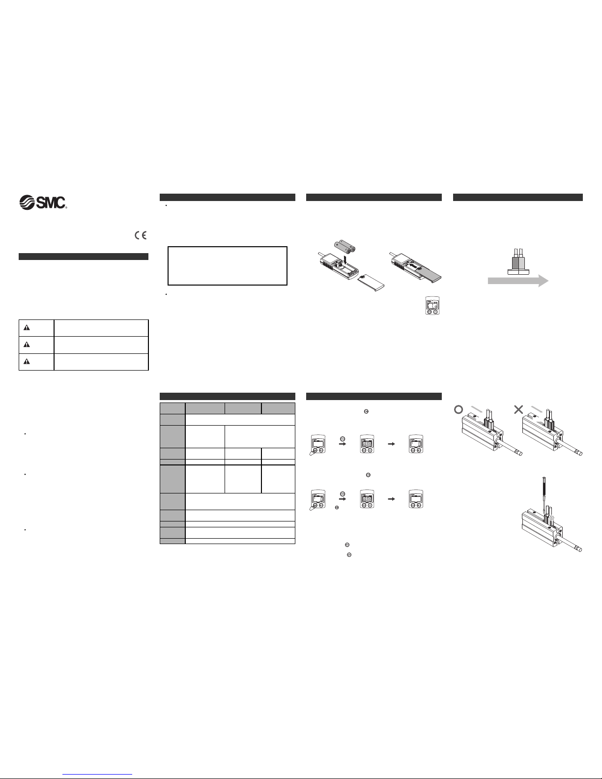
■Installation
The Measurement value is indicated with a minus (-) to distinguish
between the extension and retraction of the cylinder.
Mounting as the figure below:
∗
Extension (Stroke direction): Positive direction
Retraction (Reverse stroke direction): Reverse direction is signified with
a (-) value
If the sensor are installed
incorrectly the speed will not
be measured (as above).
5 Speed measurement
Stroke direction to be measured
Red Green
Green Red
Head endHead end
Rod endRod end
GreenRed
Speed measurement
•This product uses the magnetic field of the pneumatic cylinder piston
(with built-in magnet) to measure the time taken for the piston to pass
two magnetic sensors, and converts the time into the speed of the
cylinder.
•The speed that is displayed is the speed close to the sensor. This is
the average speed between two sensors (approx. 3.7 mm). The speed
during acceleration is the average speed.
Cycle time and count measurement
•For measurement of cycle time or count, the supplied sensor cannot be
used. An auto switch must be purchased separately.
•A 3-wire NPN type auto switch is suitable for the measurement of cycle
time or count.
The speed results may vary depending on the conditions below.
•Individual variation between cylinders with built-in magnet.
•Magnetic characteristics due to cylinder bore size.
•Variation due to the magnetic field around the cylinder.
•Individual variation between sensors.
•Variation due to temperature change.
∗1: AA alkaline battery is not included. Prepared by the user.
∗2: For speed measurement mode, use the sensors supplied.
(Do not use any other sensor.)
∗3: For cycle time measurement mode, supplied sensor cannot be used (auto switch is
not included and must be purchased).
Auto switch (SMC 3-wire NPN auto switch) and connectors are purchased
separately.
∗4: Battery life depends on the operating environment.
■Installing the batteries
(1) Slide the lid at the rear of the unit. Insert the batteries.
Applicable battery is "AA battery (1.5 V)"
Batteries are not included. Prepared by the user.
Make sure the polarity is correct when inserting the batteries.
(2) Close the lid after inserting the batteries.
(3) When the product is used and the battery has expired,
the low residual battery error will be displayed.
Replace the batteries.
■Wiring
•Connection of M8/M12 connector
(1) Tighten by rotating the knurled part of the connector body. Connection
is complete when the knurled part is fully tightened.
(2) Check that the connection is not loose.
•Assembilng the Auto switch and connector
Refer to "Assembly Procedure" attached to the connector for wiring of
PCA-1557730 (connector for M8) or PCA-1557743 (connector for M12).
Connect the lead wire colours as specified by the connector.
To obtain the operation manual for this product, please contact SMC.
To obtain the operation manual for this product, please contact SMC .
■Power ON
The power turns ON when the button is pressed.
All segments will light up for 1 second when the power supply turns ON.
The device will then be in its previous mode of operation.
∗: Default mode at the time of shipment from the factory is "Speed measurement
mode".
All segmentsONChanges to the previous
measurement mode.
■Power OFF (Auto Power Off function)
The power turns OFF when the button is held for 3 seconds or longer.
If no buttons are pressed for 15 minutes, the power will turn OFF
automatically. (Auto Power Off function)
∗: Auto Power Off is disabled during measurement.
■Toggling the back light
When the power is ON and the back light is OFF, the back light is turned
ON by pressing the button for 5 seconds or longer.
When the power is ON and the back light is ON, the back light is turned
OFF by pressing the button for 5 seconds or longer.
∗
: Although it is possible to measure when the sensor is mounted in reversed
d
irection, the displayed direction will be reversed.
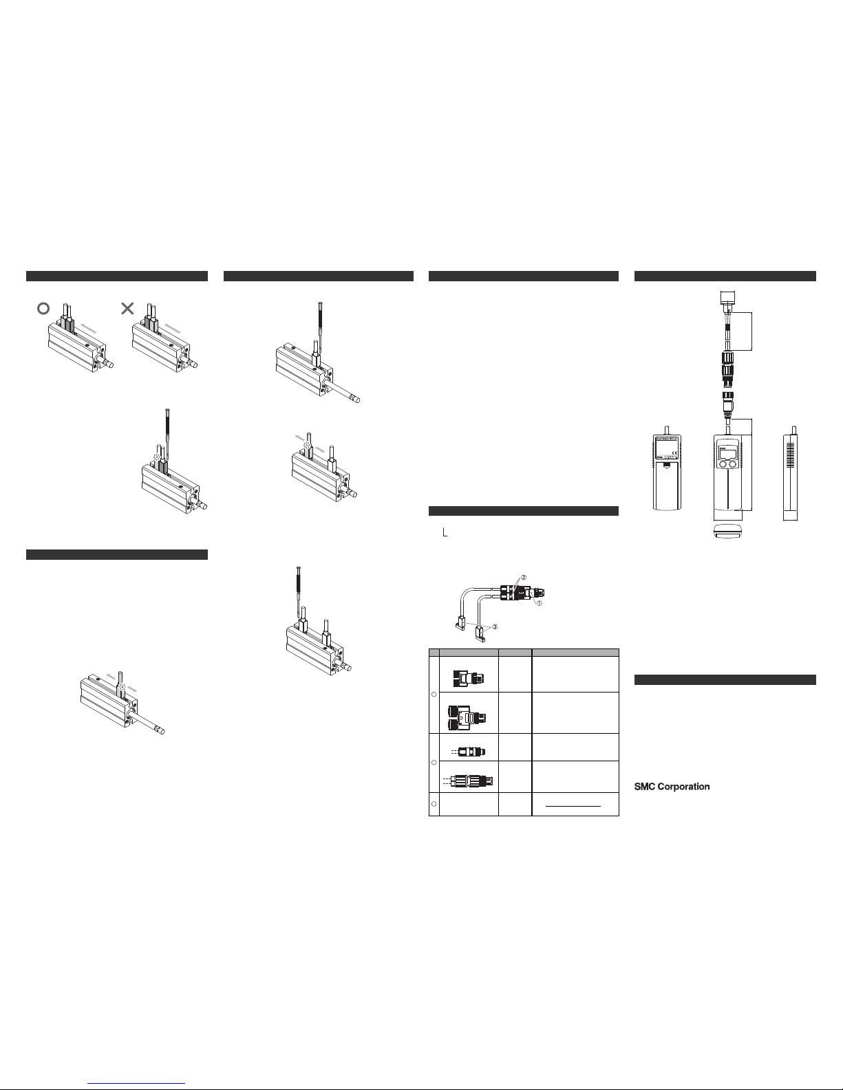
○Switch setting
(1) Fully extend the rod, and slide the sensor towards the rod end.
(2) Stop the sensor when the green LED
turns ON, and fix the sensor with the
mounting screw.
Tightening torque is 0.1 to 0.2 Nm.
∗: When the sensor is installed, the
speed from Rod to Head may not be
displayed depending on the type of
cylinder.
All segments
ON
Pressing the
button
for 3 sec.
or longer
Power OFF
(3)
URL http://www.smcworld.com (Global) http://www.smceu.com (Europe)
Specifications are subject to change without prior notice from the manufacturer.
© 2015 SMC Corporation All Rights Reserved
10 Contacts
AUSTRIA (43) 2262 62280-0
NETHERLANDS
(31) 20 531 8888
BELGIUM (32) 3 355 1464
NORWAY
(47) 67 12 90 20
CZECH REP. (420) 541 424 611
POLAND
(48) 22 211 9600
DENMARK (45) 7025 2900
PORTUGAL
(351) 21 471 1880
FINLAND (358) 207 513513
SLOVAKIA
(421) 2 444 56725
FRANCE (33) 1 6476 1000
SLOVENIA
(386) 73 885 412
GERMANY (49) 6103 4020
SPAIN
(34) 945 184 100
GREECE (30) 210 271 7265
SWEDEN (46) 8 603 1200 HUNGARY (36) 23 511 390
SWITZERLAND (41) 52 396 3131 IRELAND (353) 1 403 9000
UNITED KINGDOM
(44) 1908 563888
ITALY (39) 02 92711
BULGARIA (359) 2 974 4492
ESTONIA (372) 651 0370
ROMANIA
(40) 21 320 5111
LATVIA
(371) 781 77 00
LITHUANIA
(370) 5 264 8126
9 Outline Dimensions (mm)
6 Cycle time measurement
5 Speed measurement (Continued)
yy
40
20
POWER
LIGHT
110230
500
D-F8N
SMC
20
8 How to order
IN574-95 (Speed meter + Sensor: For speed measurement)
IN574-73 (Sensor: For speed measurement)
I
N574-TFT04
Red
Green
Green
Red
Head end
Rod end Rod end
Head end
○Switch setting
(1) Fully retract the rod, and slide the sensor towards the head end.
To obtain the operation manual for this product, please contact SMC.
■Installation
•This product can measure the travel time (cycle time) which is the time
taken from the retracted end to the extended end of the cylinder.
•Mount the Auto switch so that the switch output is detected when the
rod is in the extended end or retracted end.
•Measurement at the intermediate position of the stroke is not possible.
•Auto switches are interchangeable. Both can be mounted to the rod or
head end.
∗: Like the speed measurement mode, cylinder travel direction is indicated. For
the measurement of the retraction, the value is displayed with (-).
Installation example
(1) Supply air to the cylinder to fully extend the rod and to hold it there.
(2) Adjust the Auto switch position so that the cylinder magnet is at the
centre of the Auto switch operation range.
(3) Fix with mounting screw.
For the tightening torque, refer to the Auto switch operation manual.
Head end
Rod end
6 Cycle time measurement (Continued)
(4) Fully retract the rod to the head end.
(5) Adjust the other Auto switch position so that the cylinder magnet is at
the centre of the Auto switch operation range.
Head end
Rod end
(6) Fix with mounting screw.
For the tightening torque, refer to the Auto switch operation manual.
To obtain the operation manual for this product, please contact SMC.
7 Count measurement
■Installation
•Count the operation time of the cylinder per minute.
•Refer to the installation method for the measurement of cycle time.
Detecting sensor
Auto switch
SMC 3-wire NPN type x 2
Y branch connector
Assembly type connector
•For cycle time and count measurement
Select the connector for the measurement of cycle time and count
measurement.
Y branch connector
(For M8)
Names Product No.
PCA-1557798
Y branch connector
(For M12)
Assembly type connector
(For M8)
PCA-1557785
Assembly type connector
(For M12)
PCA-1557730
Detecting sensor
Auto switch
SMC 3-wire NPN type
1
No.
2
3
PCA-1557743
D-∗
D-∗PC
Application
Two Auto switches with M8 connector
can be connected.
Two Auto switches with M12 connector
can be connected.
Mount to the end of the Auto switch lead
wire.
Used with PCA-1557798.
Mount to the end of the Auto switch
lead wire.
Used with PCA-1557785.
Refer to the SMC web site
(URL http://www.smcworld.com
) about
the Auto switch.
To obtain the operation manual for this product, please contact SMC.
If the sensor are installed
incorrectly the speed will not
be measured (as above).
(2) Stop the sensor when the green LED
turns ON, and fix the sensor with the
mounting screw.
Tightening torque is 0.1 to 0.2 Nm.
∗: When the sensor is installed, the speed from
Rod to Head may not be displayed
d
epending on the type of cylinder.
 Loading...