

SMC Networks IMU-007, IMU-008, IMU-106, IMU-108, IMU-107 User Manual
...
IMU User Guide revision 3.1 SMC Ship Motion Control www.shipmotion.eu
SMC IMU
User Guide

IMU User Guide revision 3.1 SMC Ship Motion Control www.shipmotion.eu
Notice
The information in this User Guide is subject to change without notice.
Not all the features described in this manual are available in all motion sensor models, hardware and
firmware versions. Please check with SMC for details of model specific features such as measurement
parameters and Protocol support.
This document is property of SMC and shall not be reproduced in any form without written approval
from SMC.
SMC Ship Motion Control is not responsible for any errors in this manual or their consequences.
All rights reserved.
SMC Ship Motion Control Ltd
Email: info@shipmotion.eu
Web: www.shipmotion.eu
Tel: +46 8 644 5010

IMU User Guide revision 3.1 SMC Ship Motion Control www.shipmotion.eu
TABLE OF CONTENTS
1 INTRODUCTION .................................................................................................................... 6
1.1 RECEIVING THE MOTION SENSOR ............................................................................................ 7
2 SYSTEM DESCRIPTION .......................................................................................................... 8
2.1 SPATIAL MOVEMENT - COORDINATE SYSTEM ......................................................................... 9
2.2 DEFINITIONS .......................................................................................................................... 12
3 INSTALLATION .................................................................................................................... 13
3.1 LOCATION .............................................................................................................................. 13
3.2 MOUNTING INSTRUCTIONS ................................................................................................... 14
3.2.1 Mounting bracket - Optional ......................................................................................... 15
3.3 ALIGNMENT ........................................................................................................................... 16
3.4 DECK MOUNTED - MOUNTED ON HORIZONTAL SURFACE .................................................... 16
3.5 SIDEWAYS MOUNTING .......................................................................................................... 17
3.5.1 Top of the motion sensor pointing to the bow ............................................................. 17
3.5.2 Top of the motion sensor pointing to the starboard .................................................... 18
3.5.3 Top of the motion sensor pointing at the stern ............................................................ 18
3.5.4 Top of the motion sensor pointing to the port ............................................................. 19
3.6 MOTION SENSOR DIMENSIONS ............................................................................................. 20
3.6.1 IMU-00x Surface motion sensor .................................................................................... 20
3.6.2 IMU-00x 30m depth rated motion sensor ..................................................................... 21
3.6.3 IMU-10x Surface motion sensor .................................................................................... 22
3.6.4 IMU-10x 30m depth rated motion sensor ..................................................................... 23
3.6.5 IMU mounting bracket optional .................................................................................... 24
3.7 ELECTRICAL COMMUNICATION ............................................................................................. 25
3.7.1 Surface motion sensor cable connection ...................................................................... 26
3.7.2 Depth rated unit ............................................................................................................ 27
3.7.3 Surface motion sensor hardware version up 8.4 .......................................................... 28
3.7.4 Surface motion sensor hardware version higher than 8.5 ............................................ 29
3.7.5 Depth rated motion sensor ........................................................................................... 30
3.7.6 Analog outputs voltage +/-10v ...................................................................................... 31
3.7.7 Analog outputs current 4-20ma .................................................................................... 32
3.7.8 IMU junction box without power supply and serial input ............................................. 32
4 MOTION SENSOR CONFIGURATION GUIDE .......................................................................... 33
4.1 IMU CONFIGURATION SOFTWARE ........................................................................................ 33
4.1.1 Default settings at the factory ....................................................................................... 34
4.1.2 General settings & setup tab ......................................................................................... 35
4.2 SERIAL ASCII PROTOCOLS....................................................................................................... 37
4.2.1 PSMCA ........................................................................................................................... 38
4.2.2 PSMCB ........................................................................................................................... 39
4.2.3 PSMCC ........................................................................................................................... 40
4.2.4 PSMCD ........................................................................................................................... 41
4.2.5 PSMCE ............................................................................................................................ 42
4.2.6 PSMCF ............................................................................................................................ 43
4.2.7 PSMCG ........................................................................................................................... 44
4.2.8 PSMCH ........................................................................................................................... 45
4.2.9 PSMCI............................................................................................................................. 46

IMU User Guide revision 3.1 SMC Ship Motion Control www.shipmotion.eu
4.2.10 PSMCJ ............................................................................................................................ 47
4.2.11 PSMCK ........................................................................................................................... 48
4.2.12 PSMCM .......................................................................................................................... 49
4.2.13 PSMCR ........................................................................................................................... 50
4.2.14 PSMCS ............................................................................................................................ 50
4.2.15 PSMCT ............................................................................................................................ 51
4.2.16 SMCU ............................................................................................................................. 51
4.2.17 PSMCV ........................................................................................................................... 52
4.2.18 DD50 .............................................................................................................................. 53
4.2.19 TCM2 ............................................................................................................................. 54
4.2.20 TRH ................................................................................................................................ 55
4.2.21 TRO ................................................................................................................................ 56
4.2.22 MDL ............................................................................................................................... 56
4.2.23 DIGILOG / OCEAN TOOLS ............................................................................................... 57
4.2.24 CDL MICROTILT .............................................................................................................. 57
4.2.25 CDL1 ............................................................................................................................... 58
4.2.26 TSS1 ............................................................................................................................... 59
4.2.27 TSS3 ............................................................................................................................... 60
4.2.28 PRDID ............................................................................................................................. 61
4.2.29 PRDID with checksum .................................................................................................... 62
4.2.30 SXN ................................................................................................................................ 63
4.3 BINARY PROTOCOLS .............................................................................................................. 64
4.3.1 ATLAS (hydrographic) .................................................................................................... 64
4.3.2 SIMRAD EM1000 & EM3000.......................................................................................... 65
4.3.3 Bosch Rexroth hexadecimal heave ................................................................................ 66
4.3.4 Binary string 2 ................................................................................................................ 67
4.3.5 Binary output Message 4 ............................................................................................... 68
4.4 ANALOG OUTPUTS ................................................................................................................. 70
4.4.1 ANALOG1 ±10V, Heave ±0.5m, Heave rate ±0.2m/s, Heave Acc 0.1m/s2 .................... 70
4.4.2 ANALOG2 ±10V, Roll ±10°, Pitch ±10°, Heave ±10M ..................................................... 70
4.4.3 ANALOG3 ±10V, Roll ±30°, Pitch ±30°, Heave ±10M ..................................................... 70
4.4.4 ANALOG4, 4~20mA, roll 0-20°, Pitch 0-20° ................................................................... 71
4.4.5 ANALOG5, 4~20mA, Heave ±6M, Pitch ±60°, Roll ±60°, STATUS .................................. 71
4.4.6 ANALOG6 ±10V, Heave ±5m, Heave rate ±5m/s, Heave Acc 5m/s2 ............................. 71
4.4.7 ANALOG7 4~20mA, Heave ±5m, Heave rate ±5m/s, Heave Acc 5m/s2 ........................ 72
4.5 ETHERNET .............................................................................................................................. 73
4.5.1 IP settings ...................................................................................................................... 74
4.5.2 Port settings................................................................................................................... 75
4.5.3 Target IP addresses........................................................................................................ 75
4.5.4 Network scan ................................................................................................................. 76
4.5.5 Windows Firewall .......................................................................................................... 77
4.6 ETHERNET PROTOCOLS.......................................................................................................... 78
4.6.1 Checksum calculation .................................................................................................... 78
4.6.2 SMC Ethernet Protocol 1 UDP ....................................................................................... 78
4.6.3 ABB smartwinch MODBUS TCP ..................................................................................... 80
4.6.4 Data types for MODBUS protocol ................................................................................. 83
4.7 CHARTS .................................................................................................................................. 84
4.8 SERIAL INPUT ......................................................................................................................... 85
4.8.1 Aiding via GPS and speed log......................................................................................... 86
4.8.2 Heading input ................................................................................................................ 87
4.9 REMOTE HEAVE TAB .............................................................................................................. 88
4.9.1 Remote heave................................................................................................................ 89

IMU User Guide revision 3.1 SMC Ship Motion Control www.shipmotion.eu
4.9.2 Lever arm ....................................................................................................................... 91
4.9.3 AHC - Active Heave Compensation ................................................................................ 93
4.10 CRANE .................................................................................................................................... 94
4.10.1 Crane zero positions and offsets ................................................................................... 94
4.10.2 IMU mounted on the crane base .................................................................................. 94
4.10.3 IMU mounted on the vessel .......................................................................................... 95
4.10.4 Setting crane distance & angle offsets .......................................................................... 96
4.10.5 Telescopic arm input data ............................................................................................. 98
4.10.6 Crane booms................................................................................................................ 100
4.10.7 String input .................................................................................................................. 101
4.10.8 Verification string and example strings ....................................................................... 103
4.11 TIME ..................................................................................................................................... 104
4.12 RECEIVED DATA ................................................................................................................... 105
4.13 OPTIONAL SMC SOFTWARE ................................................................................................. 106
5 MOTION SENSOR OPERATION ........................................................................................... 107
5.1 SETTLING TIME .................................................................................................................... 107
5.2 HEAVE OPERATION .............................................................................................................. 107
6 SERVICE AND WARRANTY .................................................................................................. 108
6.1 TECHNICAL SUPPORT ........................................................................................................... 108
6.2 WARRANTY .......................................................................................................................... 109
6.2.1 Limit of liability ............................................................................................................ 109
6.2.2 Restriction of warranty ................................................................................................ 110
7 TECHNICAL SPECIFICATIONS............................................................................................... 111
7.1 IMU-00X TECHNICAL SPECIFICATIONS ................................................................................. 111
7.2 IMU-10X TECHNICAL SPECIFICATIONS ................................................................................. 112
8 FAQ & SUPPORT ................................................................................................................ 113

6
IMU User Guide revision 3.1 SMC Ship Motion Control www.shipmotion.eu
1 INTRODUCTION
This user manual provides information about your SMC motion sensor and how to use it.
Motion sensors also known as IMUs or MRUs determine the orientation of an object relative to an
inertial frame of reference or another body. The motion sensor uses 3 accelerometers and 3
gyroscopes which are integrated with a DSP, Digital Signal Processor, to produce accurate pitch, roll
and heave information in an industry standard format. These measurements are suitable for any
maritime operation that requires attitude determination, motion compensation or dynamic
positioning. The SMC Motion sensors provide high accuracy motion measurements in all dynamic
environments.
The data output from the SMC motion sensor is sent over serial and Ethernet. As an option an analog
converter is available for V and mA outputs. The serial data can be read in any terminal software, the
SMCems, SMC IMU configuration software and many third-party applications.
The SMC motion sensors are used in a wide range of applications.
Some examples are:
- Hydrographic surveying for heave compensation using multi beam sonars, single beam
sonars and sub bottom profilers
- System integration for different type of monitoring systems such as Helideck Monitoring and
crane monitoring systems
- Active heave compensation for cranes and winches.
- Dynamic positioning systems
Products Covered in this User Guide
Surface motion sensors
Roll & Pitch (Dynamic)
Heave
Acceleration
IMU-007
0.25 RMS
N/A
0.01 m/s2 RMS
IMU-008
0.25 RMS
5cm or 5%
0.01 m/s2 RMS
IMU-106
N/A
5cm or 5%
N/A
IMU-107
0.03 RMS
N/A
0.01 m/s2 RMS
IMU-108
0.03 RMS
5cm or 5%
0.01 m/s2 RMS
Subsea motion sensors, 30 m depth rated
Roll & Pitch (Dynamic)
Heave
Acceleration
IMU-008-30
0.25 RMS
5cm or 5%
0.01 m/s2 RMS
IMU-108-30
0.03 RMS
5cm or 5%
0.01 m/s2 RMS
Custom motion sensors
Roll & Pitch (Dynamic)
Heave
Acceleration
IMU-007-L
0.25 RMS
N/A
0.01 m/s2 RMS
IMU-028
0.25 RMS
5cm or 5%
0.01 m/s2 RMS
IMU-108R-L
0.03 RMS
5cm or 5%
0.01 m/s2 RMS
IMU-108R-30
0.03 RMS
5cm or 5%
0.01 m/s2 RMS
As an option, Analog outputs are available and covered by this user guide

7
IMU User Guide revision 3.1 SMC Ship Motion Control www.shipmotion.eu
1.1 RECEIVING THE MOTION SENSOR
Unpack the equipment and remove all the packaging materials and shipping carton.
The standard motion sensors are delivered in a transit case designed to protect it from high shocks
during transit.
When the motion sensor has been received, it must be inspected for damage during shipment. If
damage has occurred during transit, all the shipping cartons and packaging materials should be
stored for further investigation. If damage is visible, a claim for shipping damage must be filed
immediately.
Because of the sensitive nature of the motion sensor the package must not be dropped.
Standard Delivered Items
• Motion Sensor
• Transit Case
• Junction Box fitted with
o Cable from Motion sensor to JB 10m, 19 core cable
o Serial Output Data cable 1.5m
o AC Input Cable 0.9m
• Calibration Certificate
• CD with IMU Configuration Software and IMU User Manual
8
IMU User Guide revision 3.1 SMC Ship Motion Control www.shipmotion.eu
2 SYSTEM DESCRIPTION
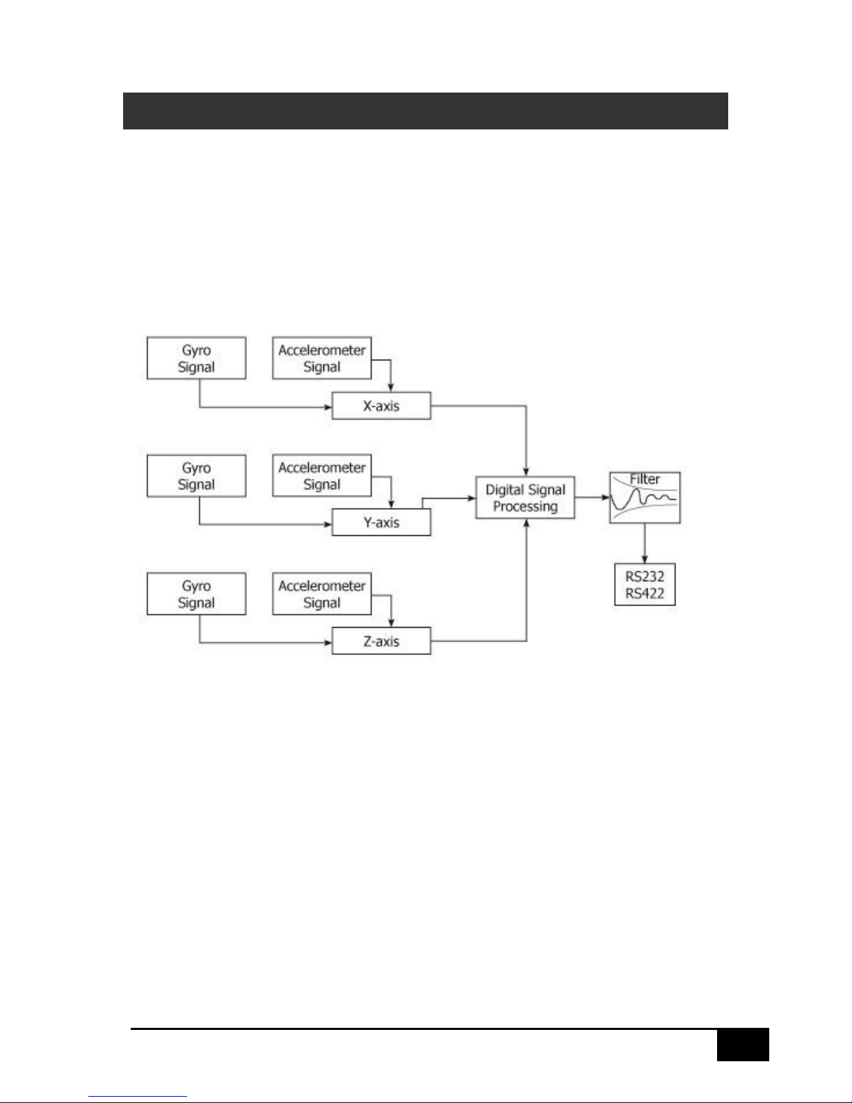
The SMC motion sensors have three separate axial measurement component groups converting
signals from actual movements via three accelerometers and three gyroscopes into output data of
angles and attitude. The output parameters are presented in a digital output string via RS422 and
RS232. On hardware versions 8.5 or higher Ethernet communication is available.
The signal from the gyroscopes are combined with the signal from the accelerometers and are
processed in a Kalman filter inside the motion sensor to provide output values for accelerations,
attitudes and angles with limited influence from noise and other inaccuracies.
Heave, surge and sway are calculated by integrating the acceleration in the X, Y and Z axis twice. The
integrated data is filtered with a high pass filter. The calculations of the distances are optimized for
continuous motion and not for static distance measurements, as the high pass filter will filter the
position over time to zero. The dynamic motion filtering is designed to measure motions over a
period between 1 s and 25 s.
Before delivery all motion sensors are calibrated. The readings from the accelerometers and angular
rate gyroscopes are calibrated for alignment, linearity and temperature variations, to ensure they
meet the performance specifications.
The calibration is optimized for angles up to +/-30 degrees of angle. The best motion sensor
performance is achieved within this angle range. If the motion sensor angle exceeds the calibrated
angular range the motion sensor will continue to measure the data, but performance may be
decreased.
9
IMU User Guide revision 3.1 SMC Ship Motion Control www.shipmotion.eu
2.1 SPATIAL MOVEMENT - COORDINATE SYSTEM
Mounting offsets for the SMC Motion sensor in the roll, pitch and Z axis can be set in the SMC IMU
configuration software to compensate for physical alignment errors in the installation. For optimum
performance align the motion sensor physically as accurate as possible before setting up offsets
electronically.
Note: The Z-axis offset is used to compensate for a physical misalignment in the Z-axis mounting
and is not used to set the yaw angle output in the motion sensor.
An improper Z-axis rotation will rotate the coordinate system and will induce roll motion readings
in the pitch axis and the vice versa.
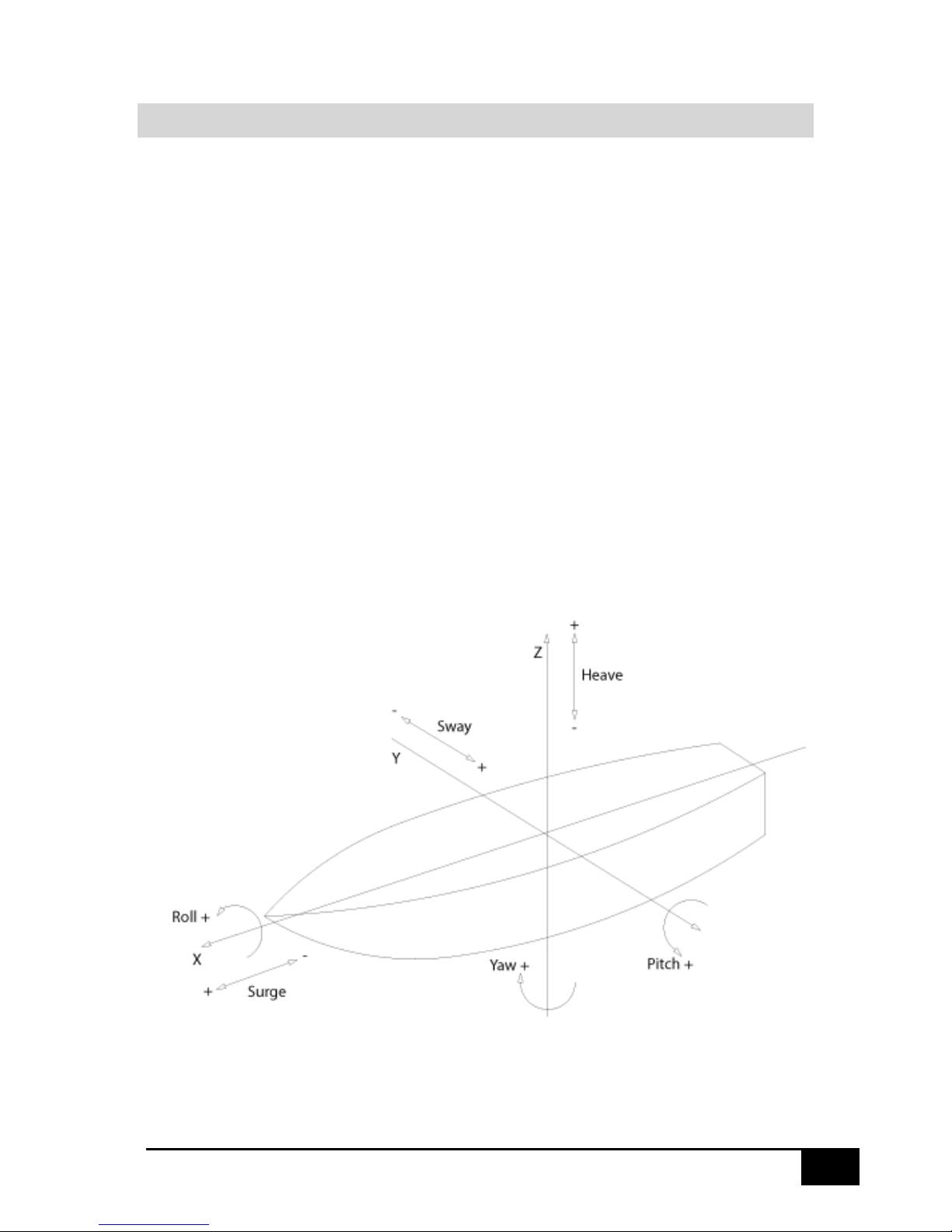
The SMC IMU default rotational and acceleration directions are defined in the drawing below. By
setting an offset the motion sensor rotates its coordinate system. From the configuration software it
is possible to invert the axis rotational directions to suit the receiving application.
Roll is the rotation around the longitudinal axis, X, the axis running from the bow to the stern of the
vessel.
Pitch is the rotation around the transverse axis, Y, the axis running from starboard to port of the
vessel.
Yaw is the rotation around the vertical axis, Z
Shown in the figure below:
10
IMU User Guide revision 3.1 SMC Ship Motion Control www.shipmotion.eu
In the SMC motion sensors, the coordinate system can be defined by a setting option in the SMC
configuration software that is included with the motion sensor. The user can choose between the
IMU coordinate system and the Earth Coordinate system.
The default setting for the SMC motion sensor is Earth Coordinates without earth G in Acc.
The SMC motion sensor defines its body axis from the Tait-Bryan (z-y-x) angles in the order yaw,
pitch, roll to describe the orientation of a vessel.
In the Earth Coordinate system positive Z is vertical with reference to the earth horizon. The X-axis in
the earth coordinate system has the same direction as the X-axis of the IMU coordinate system
projected onto the horizontal plane of the earth. The Y-axis is horizontal and is perpendicular with
respect to the earth fixed X-axis and has close to the same direction as the IMU coordinate Y-axis.
To obtain the accelerations in the IMU coordinate system the accelerations measured by the motion
sensor are rotated with a three-dimensional calculation with respect to the mounting angles offsets.
To obtain the accelerations in the earth fixed system the accelerations measured in the motion
sensor in the IMU coordinate system are rotated with a three-dimensional calculation with respect to
the current value of the roll and pitch angles and their offsets.
The accelerations are in sent in the selection for the IMU coordinate system and is not related to the
selection of the Heave, surge and sway output selection in the motion sensor.
Heave, surge and sway motions are calculated in the earth
fixed coordinate systems as default. The calculations of these
linear motions are done by taking the accelerations in the
Earth Coordinate system and double integrate these to obtain
surge, sway and heave positions.
If the IMU coordinates is selected for the Surge, sway and
heave in the IMU configuration software these values are
calculated three-dimensional using the roll and pitch angular
data before being output.
The surge, sway and heave velocities are the derivatives of
the surge, sway and heave positions.
For the Roll, Pitch and Yaw calculations when using the earth coordinate system selection, the threedimensional rotation corresponding to the motion sensor readings is composed (conjugated) with
the three-dimensional rotation of the mounting offsets.
After the internal measured data in the IMU coordinate system has been rotated into the earth
coordinate system the Roll, Pitch and Yaw angles are calculated.
The roll, pitch and yaw velocities being output in the earth coordinate system are the derivatives of
the corresponding angular values.

11
IMU User Guide revision 3.1 SMC Ship Motion Control www.shipmotion.eu
The roll, pitch and yaw velocities being output in the IMU coordinate system are the roll, pitch and
yaw velocity values measured by the motion sensor and three-dimensional rotated, multiplicatively
composed, by the mounting offsets entries.
All compositions of three-dimensional rotations are done by first converting the Tait-Bryan angles to
quaternions. Then performing the composition by using quaternion multiplication and finally either
obtaining the angles by the citation above or the rotation matrix.

12
IMU User Guide revision 3.1 SMC Ship Motion Control www.shipmotion.eu
2.2 DEFINITIONS
Alignment
The alignment of the motion sensor is the positioning of the IMU onto the structure of the rig or
vessel. The physical alignment must be done as accurately as possible and then it can be fine-tuned
in the system configuration software by entering offsets for roll (X), pitch (Y) and the Z-axis.
Yaw in the SMC IMU units
Without an external aiding input the yaw in the SMC motion sensor will drift over time and so it
cannot be used as an absolute heading output. Positive yaw is a clockwise rotation. The yaw output
from the SMC unit, when it is not aided from an external heading input, is the integration of the yaw
gyroscope or the integrated rotation in the Z axis in the earth coordinate system.
Roll
Roll is the rotation about the roll axis (X) of the vessel. SMC defines the port up as a positive roll.
Pitch
Pitch is the rotation about the pitch axis (Y) of the vessel. SMC defines the bow down as a positive
pitch.
Heave
Heave is the vertical dynamic motion of the vessel. The heave is calculated by a double integration of
the vertical acceleration. The vertical position is filtered with a high pass filter. Heave measures the
relative position dynamically and cannot be used for a static height position measurement. An
upwards motion is defined as a positive heave.
Surge and Sway
Surge and Sway are the horizontal dynamic motion of the vessel. Surge is the linear motion along the
roll axis; a positive surge is when the vessel is moving in the bow direction. Sway is the linear motion
along the pitch axis where a positive sway is in the port direction. The surge and sway calculation are
attained by a double integration of the horizontal acceleration. The horizontal position is filtered
with a high pass filter. The dynamic horizontal linear measurement is a relative position and cannot
be used for a static horizontal position measurement.
Center of Gravity
Centre of gravity CG is the mass center of a vessel.
X-axis/Roll axis
The X axis is the bow/stern axis in the vessel. Rotation in the X axis will generate a roll motion where
a positive rotation is port side up.
Y-axis/Pitch axis
The Y axis is the port/starboard axis in the vessel. Rotation in the Y axis will generate a pitch motion
where a positive rotation is bow down.
Z-axis
The Z axis is the vertical axis pointing up and down in the vessel. Rotation in the Z axis will generate a
yaw motion, where positive yaw is a clockwise rotation.
RMS
Root mean square (RMS) is a statistical measure of the magnitude of a varying quantity.

13
IMU User Guide revision 3.1 SMC Ship Motion Control www.shipmotion.eu
3 INSTALLATION
The SMC motion sensor must be installed according to the instructions in this manual.
The motion sensor is designed to be installed in an internal environment.
3.1 LOCATION
The optimal location for the SMC motion sensor is as close as possible to the vessels center of gravity
(CG). However, for certain applications, mainly when heave and accelerations are to be measured at
a specific location, it is advisable to mount the motion sensor as close as possible to the actual
measurement point, for example in Helideck Monitoring Systems and some hydrographic survey
systems.
Recommendations for location of the motion sensor to obtain optimal performance:
Roll & Pitch
When mounting the SMC motion sensor, take care to align the motion sensor to the vessels roll,
pitch and Z axis. If there is a rotation misalignment in the Z-axis, roll motions will induce errors in
pitch measurements and vice versa.
Small alignment errors can be adjusted mathematically inside the motion sensor. The alignment
offsets can be set from the SMC IMU configuration software.
Heave/acceleration
If the motion sensor is equipped with Heave/acceleration measurement it is recommended that the
motion sensor is placed as close to the point where Heave/acceleration is to be measured. For a
helideck installation, it is required to install the motion sensor within 4 meters from the center of the
helideck.
Temperature
The SMC motion sensors have been calibrated and designed to work within the stated temperature
range as specified in the motion sensor technical specifications. SMC recommend that the motion
sensor is mounted in a location without extreme variations in temperature.
Vibrations
Avoid mounting the motion sensor on any hull location that is subject to substantial vibrations. Also,
avoid mounting a sensor near to machines with sporadic operation e.g. hydraulic pumps. The use of
dampers between the Motion Sensor mounting plate or fixture points may be of benefit in
installations where vibrations are present. Care ought to be taken to ensure the dampers are
sufficiently firm so as not to introduce a sag and therefore alignment errors. Heavy vibrations will
reduce measurement performance mainly on the positioning outputs as for example heave as these
are calculated from the accelerations.
Weather protection
The SMC IMU-007, IMU-008, IMU-106, IMU-107 and IMU-108 are as a standard IP66 protection
rated. The standard surface motion sensor is designed to be mounted in a sheltered environment, an
enclosure is highly recommended to prolong service life and life time expectations.
The SMC IMU-108-30 is IP68 water resistant to 30 meters depth or optionally 1000 meters.

14
IMU User Guide revision 3.1 SMC Ship Motion Control www.shipmotion.eu
Mounting orientation
The Motion Sensor is calibrated from the factory for either Deck or Sideways orientation. Deck
orientation is when the Motion Sensor is mounted on a horizontal surface with the connector
pointing upwards. Deck mounting calibration is the default orientation. Sideways orientation is when
the motion sensor is calibrated to be mounted on a vertical surface.
A motion sensor that has been calibrated for Deck mounting cannot be used in a sideways mounting
and vice versa without recalibration of the motion sensor at the factory.
3.2 MOUNTING INSTRUCTIONS
The Motion sensor base plate has been specifically designed to enable ease of installation and
alignment.
The SMC Motion sensor is shipped without mounting screws or bolts. The base plate can be fixed
with M6 (max M8) screws or bolts with washers. The dimensions of the motion sensor for the
mounting locations can be found in Chapter 3.6
After drilling any holes for mounting, be sure to de-burr the holes and clean the mounting location of
any debris that can induce mounting offsets.
Mount and screw the motion sensor in position, make sure to align the motion sensor as accurately
as possible with the vessels coordinate system.
A motion sensor calibrated for deck mounting/horizontal surface, must be mounted with the
connector pointing upwards. It is not designed to be mounted with the connector pointing
downwards.
In the SMC IMU Configuration Software there is a function to fine tune the motion sensor alignment
in the X, Y and Z axis. This setting will rotate the coordinate system inside the motion sensor. See
chapter 4.1 on IMU Configuration Software for further instructions.
When mounting the motion sensor sideways there are 4 mounting options in the SMC IMU
Configuration Software to rotate its coordinate system correctly. For more information, see chapter
3.5 for sideways calibrated setup. If an incorrect mounting selection is chosen, the coordinate system
will be inverted. In this case, the roll motion will become the pitch motion or alternatively the
positive negative rotation of the angles will be inverted.
When the motion sensor is calibrated for sideways mounting, connector pointing horizontally, and is
mounted upside down, with the single notch pointing in the wrong direction, the output signal from
the motion sensor will display – 180 degrees wrong angle for roll output. If the Motion Sensor is
mounted incorrectly it will not work within its calibrated range and will output inaccurate values.
15
IMU User Guide revision 3.1 SMC Ship Motion Control www.shipmotion.eu
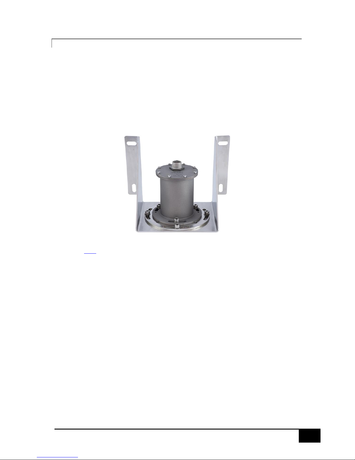
3.2.1 MOUNTING BRACKET - OPTIONAL
An optional mounting bracket is available, designed to simplify wall mounting installations combined
with easy motion sensor alignment. One advantage with the mounting bracket is that the motion
sensor can be removed for servicing or recalibration and repositioned in exactly the same position.
The bracket base plate has two pins that correspond to two of the notches in the Motion sensor
base. Alignment adjustments can then be made by rotating the bracket adapter.
The mounting bracket is delivered with a mounting adapter and screws for fixating the motion sensor
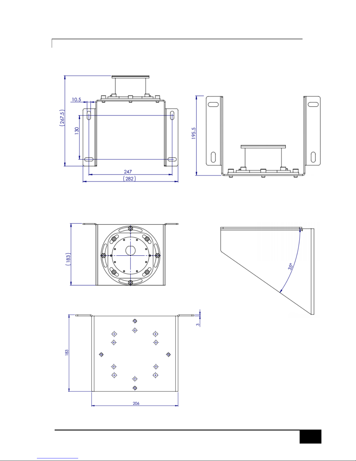
to the bracket. The mounting bracket is produced in Stainless steel 316.
The adapter, included with the bracket, allows 45 degrees of rotational adjustment.
See chapter 3.6.5 for details of the mounting bracket dimensions.
16
IMU User Guide revision 3.1 SMC Ship Motion Control www.shipmotion.eu
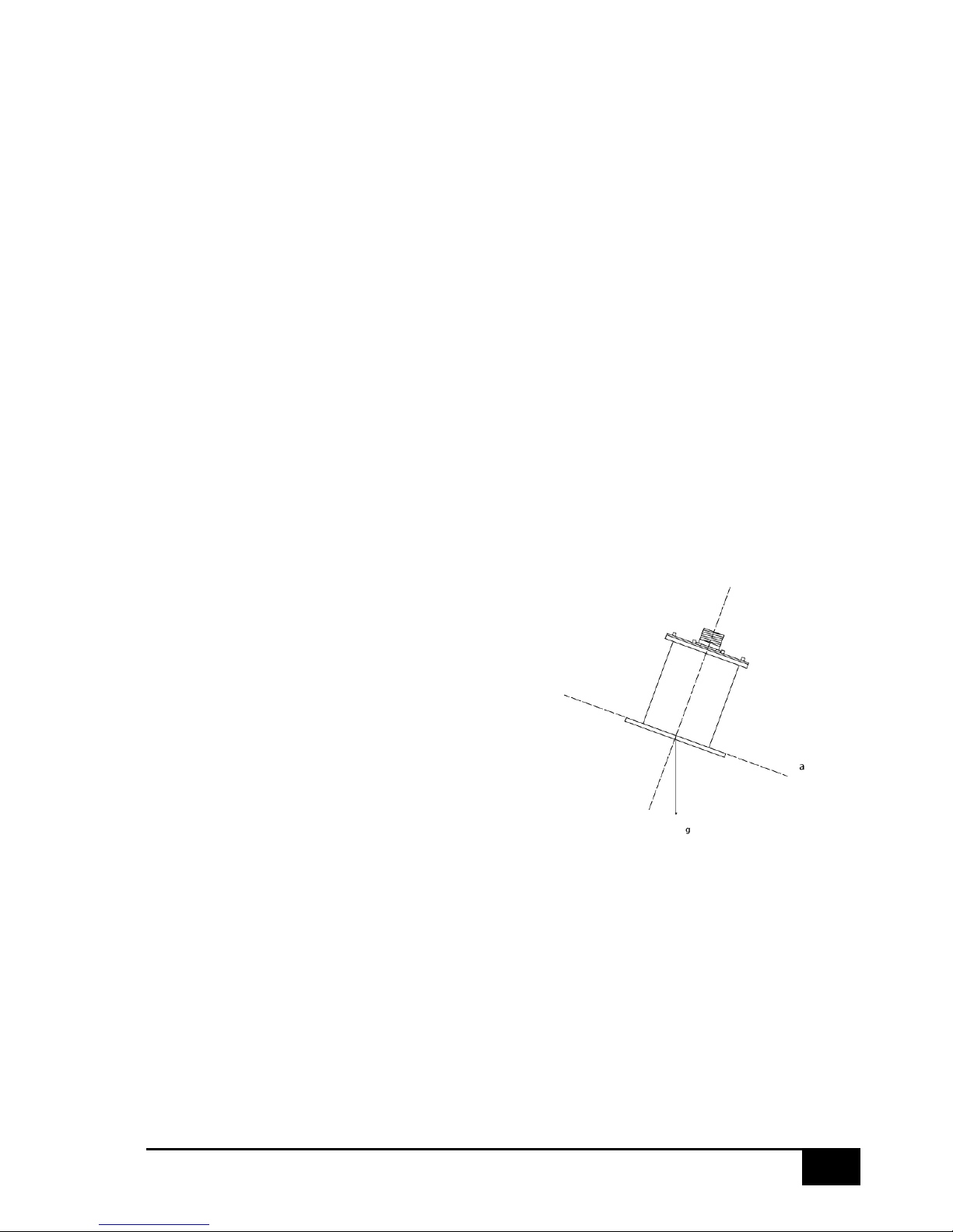
3.3 ALIGNMENT
To achieve maximum performance of the motion sensor, it is important to perform an accurate
alignment of the motion sensor along the vessel longitudinal axis. The physical alignment must be as
accurate as possible using the notches on the motion sensor mounting plate for reference.
For the deck mounted standard motion sensor, the single notch is to be pointing to the fore direction
of the vessel. A misalignment in the Z axis rotation (yaw) will generate a cross axis motion, where
pitch will generate a roll reading from the motion sensor and vice versa. From the SMC IMU
Configuration Software, it is possible to fine tune the alignment errors from the installation of the
motion sensor.
Note: The Z-axis alignment is only to be used to correct the physical misalignment and not to change
the yaw output reading from the motion sensor.
3.4 DECK MOUNTED - MOUNTED ON HORIZONTAL SURFACE
When the motion sensor is delivered for Deck mounting the motion sensor cannot be used for
sideways mounting without a recalibration at the factory.
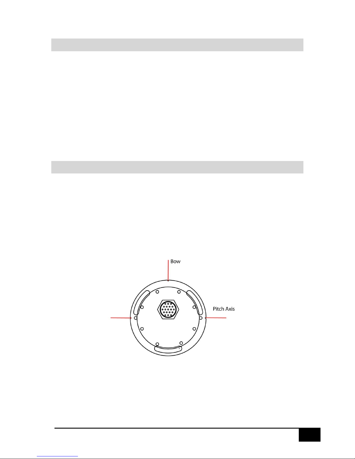
Mounting of the motion sensor must be carried out with the mounting plate placed horizontally. The
notches on the plate mark the orientation points of the motion sensor. The indexes marking the Pitch
axis must be aligned to port/starboard, along the vessels center of rotation or on the axis you have
defined. The single notch is to be mounted pointing to the fore of the vessel. In the figure below the
Motion Sensor viewed from the top.
17
IMU User Guide revision 3.1 SMC Ship Motion Control www.shipmotion.eu
3.5 SIDEWAYS MOUNTING
When the Motion sensor is delivered for Sideways mounting the motion sensor cannot be used for
Deck mounting without a recalibration at the factory.
The mounting of the motion sensor must be carried out with the mounting plate oriented vertically.
The notches on the mounting plate mark the orientation points of the motion sensor.
The single notch must be mounted pointing horizontally to the bow/stern/port/starboard of the
vessel.
Depending on the mounting orientation the Motion sensor will need its coordinate system to be
selected in the SMC IMU configuration software Mounting Orientation options.
Note: The Motion sensor cannot be mounted in the sideways orientation unless it has been
specifically calibrated to do so. Contact SMC if clarification is required.
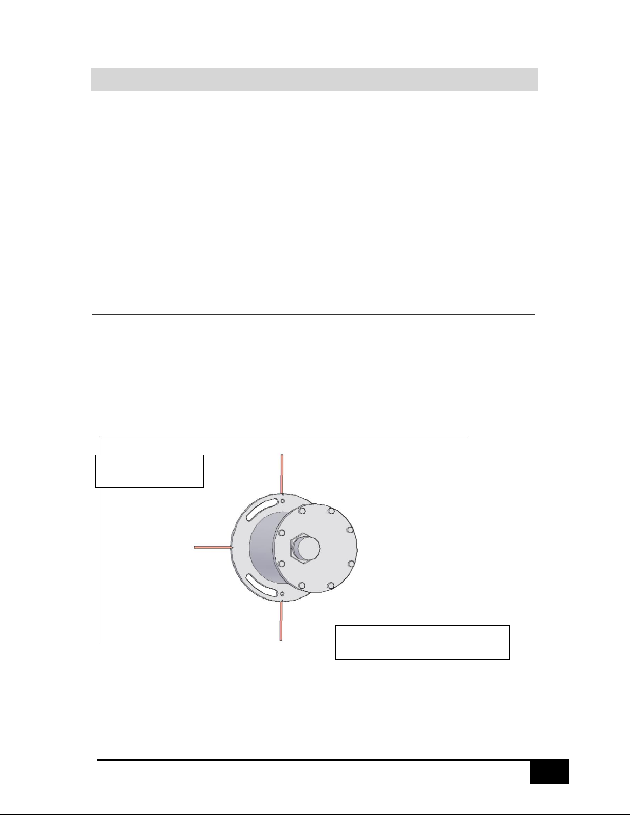
3.5.1 TOP OF THE MOTION SENSOR POINTING TO THE BOW
When the Motion sensor top, where the connector is located, is pointing to the Bow of the vessel the
single notch must be pointing horizontally to Starboard.
In the SMC IMU Configuration Software IMU top to the Bow must be selected.
Single Notch Pointing
to Starboard
Motion Sensor Connector Pointing
to the Bow
18
IMU User Guide revision 3.1 SMC Ship Motion Control www.shipmotion.eu
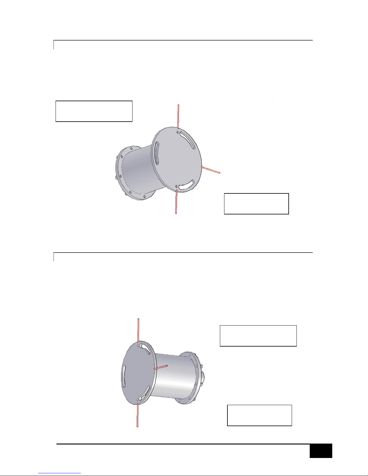
3.5.2 Top of the motion sensor pointing to the starboard
When the Motion sensor top, where the connector is located, is pointing to the Starboard of the
vessel the single notch must be pointing horizontally to the Stern.
In the SMC IMU Configuration Software IMU top to the Starboard must be selected.
3.5.3 TOP OF THE MOTION SENSOR POINTING AT THE STERN
When the Motion sensor top, where the connector is located, is pointing to the Stern of the vessel
the single notch must be pointing horizontally to Port.
In the SMC IMU Configuration Software IMU top to the Stern must be selected.
Motion Sensor Connector
Pointing to Starboard
Single Notch Pointing
to the Stern
Motion Sensor Connector
Pointing to the Stern
Single Notch Pointing
to Port
19
IMU User Guide revision 3.1 SMC Ship Motion Control www.shipmotion.eu
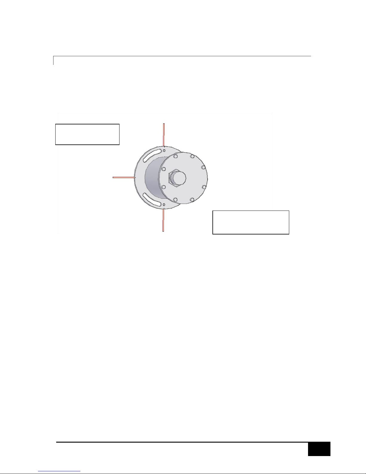
3.5.4 TOP OF THE MOTION SENSOR POINTING TO THE PORT
When the Motion sensor top, where the connector is located, is pointing to the Port of the vessel the
single notch must be pointing horizontally to the Bow.
In the SMC IMU Configuration Software IMU top to the Port must be selected.
Single Notch Pointing
to the Bow
Motion Sensor Connector
Pointing to Port
20
IMU User Guide revision 3.1 SMC Ship Motion Control www.shipmotion.eu
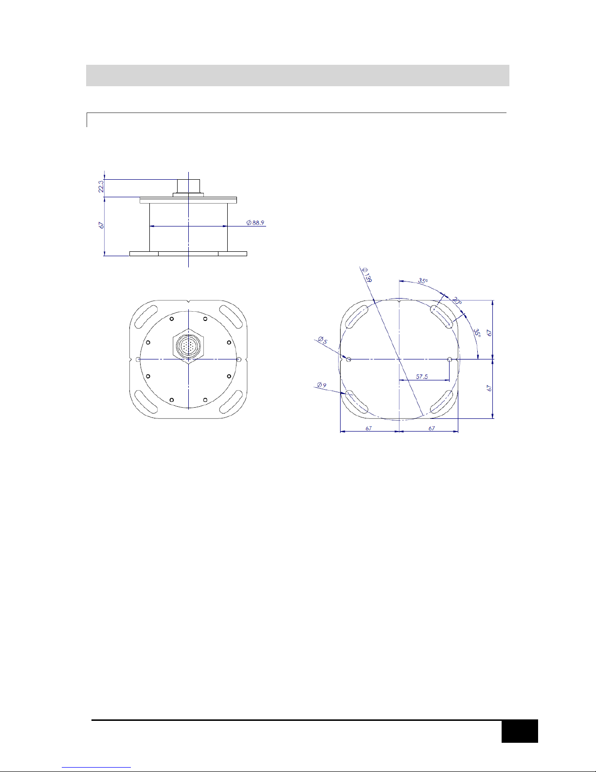
3.6 MOTION SENSOR DIMENSIONS
3.6.1 IMU-00X SURFACE MOTION SENSOR
Dimensions in mm
21
IMU User Guide revision 3.1 SMC Ship Motion Control www.shipmotion.eu
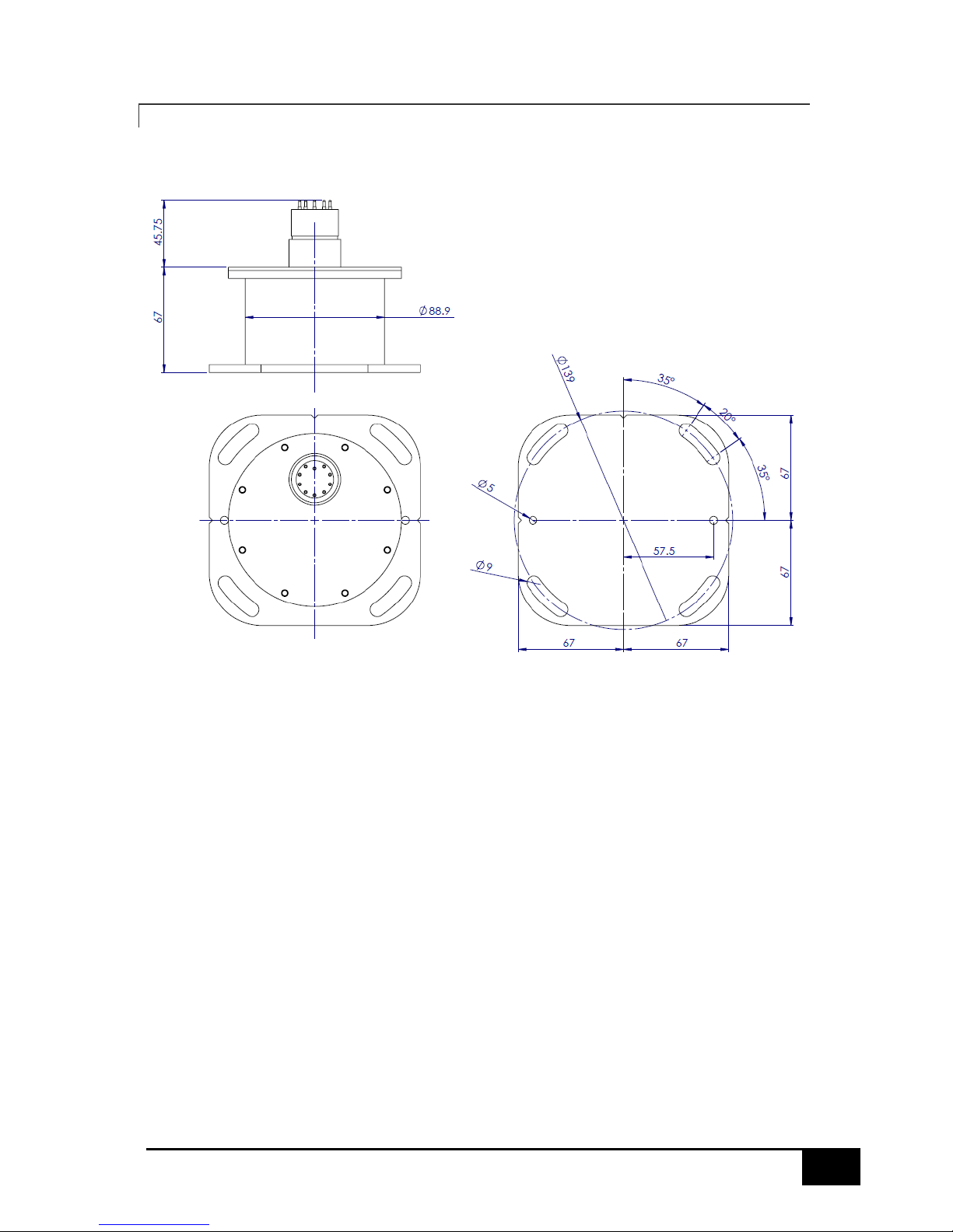
3.6.2 IMU-00X 30M DEPTH RATED MOTION SENSOR
Dimensions in mm
22
IMU User Guide revision 3.1 SMC Ship Motion Control www.shipmotion.eu
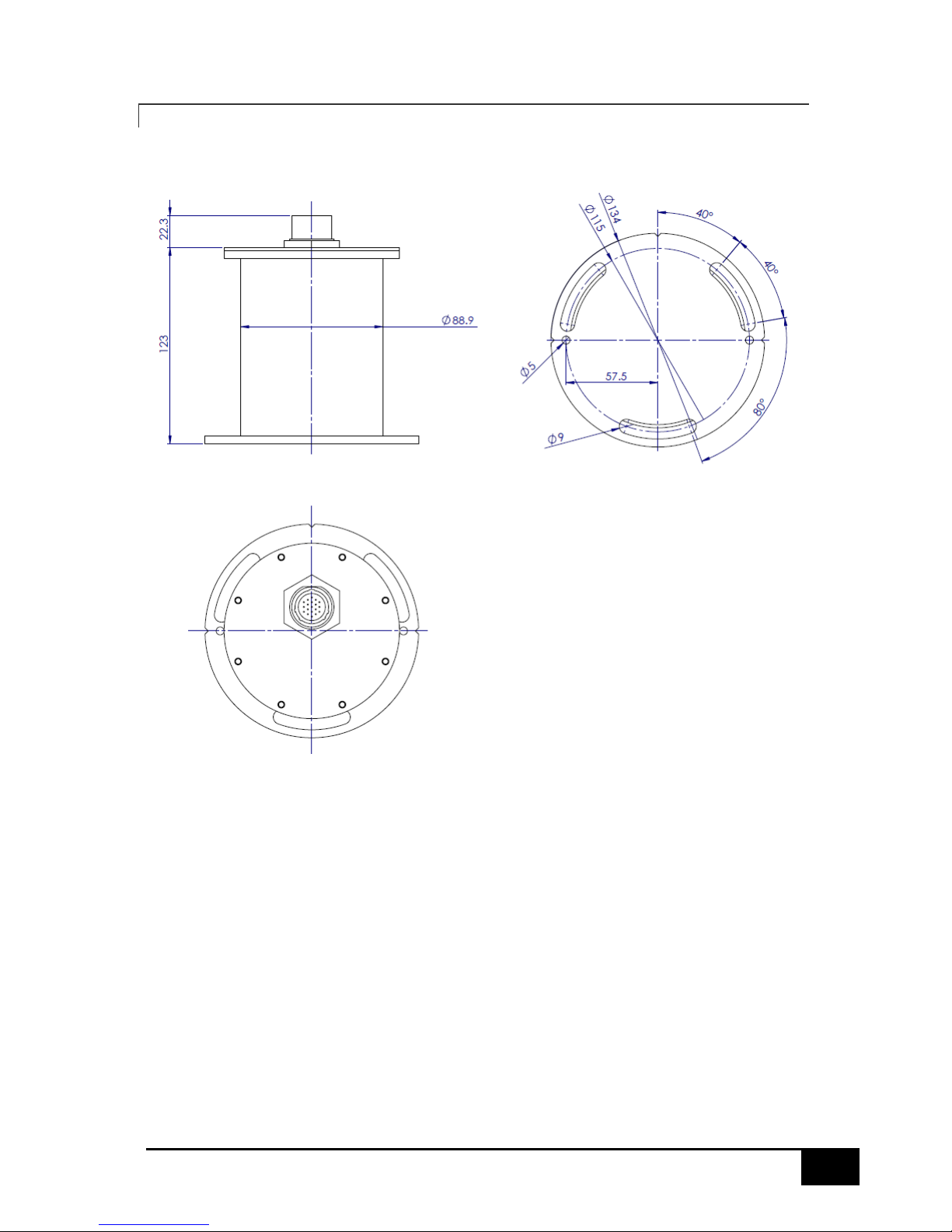
3.6.3 IMU-10X SURFACE MOTION SENSOR
Dimensions in mm
23
IMU User Guide revision 3.1 SMC Ship Motion Control www.shipmotion.eu
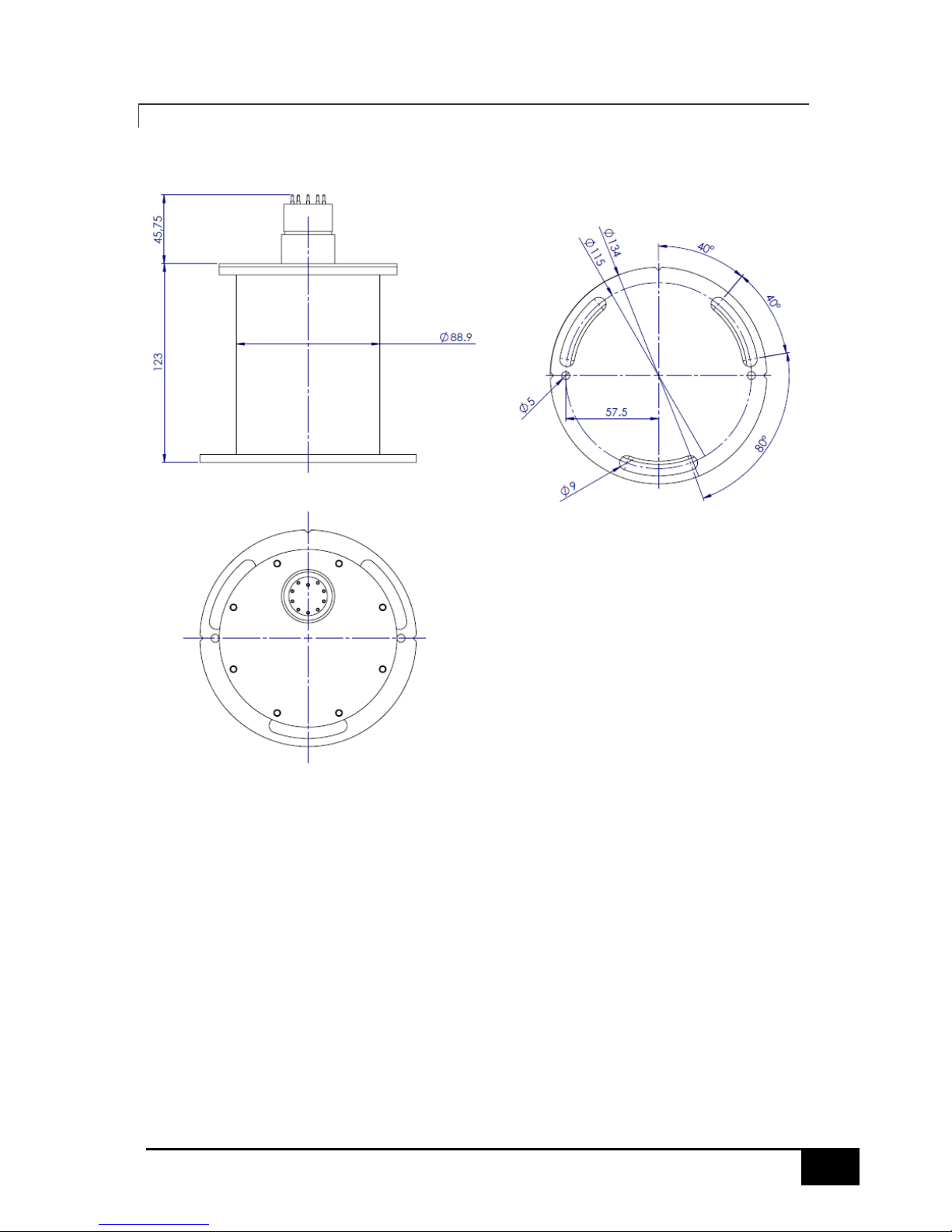
3.6.4 IMU-10X 30M DEPTH RATED MOTION SENSOR
Dimensions in mm
24
IMU User Guide revision 3.1 SMC Ship Motion Control www.shipmotion.eu
3.6.5 IMU MOUNTING BRACKET OPTIONAL
Dimensions in mm

25
IMU User Guide revision 3.1 SMC Ship Motion Control www.shipmotion.eu
3.7 ELECTRICAL COMMUNICATION
The SMC Motion sensors are powered with a standard 12 VDC or 24 VDC supply. It is possible
however to supply power at any voltage between 10 VDC and 30 VDC. The power consumption
during normal conditions is about 2 watts for hardware versions below 8.4 and 3 watts for hardware
version 8.5 and higher.
The resistance of power cables must be so that the voltage does not drop below 12 VDC for the
motion sensor operation. The thickness of power cables is such that there is no more than a 2V drop
with a 50mA current applied over an exceptional length of cable.
The SMC Motion sensors do not have an on/off switch. The motion sensor operates as soon as power
is supplied to it. There is an initialization period that prevents the motion sensor from outputting
numerical data for the first 1 minute after the motion sensor has been powered up.
The SMC Motion sensors have both RS232 and RS422 serial outputs as standard. The motion sensor
is simultaneously communicating over both RS232 and RS422 and no configuration is needed inside
the motion sensor to activate the communications. For motion sensor firmware versions from 3.22
and higher one of the serial input ports can be used for outputting data. The baudrate and output
rate will be the same on all outputs. The string is selectable for the comport 1/2 and comport 3
separately. For firmware versions below 3.22 Only one data string output format, protocol, can be
used for both serial outputs.
Motion sensors from hardware version 8.5 are equipped with an Ethernet interface. The SMC Motion
Sensor can supply data output on both the serial and Ethernet interfaces at the same time.
In the standard delivery, the motion sensor junction box is equipped with a power cable, a motion
sensor cable and a serial DB9 cable for RS232 or RS422 communication. The Junction Box factory preconfiguration for RS232 or RS422 can be changed in the field by modifying the wiring of the serial
cable inside the junction box. See the wiring diagram for wiring details.
The RS232 cable consists of single twisted-pair conductors, 2 wires, for full communication and a
signal ground wire. RS232 is designed for short distance communication, max 15 meters.
The RS422 cable consists of two twisted-pair conductors, 4 wires, for full communication.
The RS422 communication can achieve data transfer over long distance cables, up to 1000 meters.
The RS232 and RS422 cable normally terminates with a conventional DB9 connector.
The Ethernet cable consists of two twisted-pair conductors, 4 wires, for bi-directional
communication, following the RJ45 568B standard. The maximum cable length is approximately
100m.
Two RS232 serial ports are also available for aiding the motion sensor by GPS or Compass input.
IMU-10x with a hardware below 2.72 does not have the serial input communication ports.
Permanent damage to the motion sensor may occur if power is applied to the digital
connections. It is important to check the power connections by measuring the
voltage at the connector prior to the motion sensor being connected. Damage
resulting from incorrect connection is not covered by the warranty.

26
IMU User Guide revision 3.1 SMC Ship Motion Control www.shipmotion.eu
3.7.1 SURFACE MOTION SENSOR CABLE CONNECTION
IMU Connector
Cable Colour
IMU Function
External device
A
White
RS232 – RxD main
DB9 pin3 – TxD
B
Red
RS232 – TxD main
DB9 pin2 – RxD
C
Brown
RS422 – TxD+ main
DB9 pin3 – RxD+
D
Orange
RS422 – TxD- main
DB9 pin4 – RxD-
E
Green
RS422 – RxD- main
DB9 pin1 – TxD-
F
Purple
RS422 – RxD+ main
DB9 pin2 – TxD+
G
Yellow
RS232 – TxD serial aiding/input
DB9 pin2 – RxD
H
Transparent
RS232 – RxD serial aiding/input
DB9 pin3 – TxD
J
Black
RS232 – TxD serial aiding/input
DB9 pin2 – RxD
K
Blue
RS232 – RxD serial aiding/input
DB9 pin3 – TxD
L
Grey
Supply Voltage -
M
Pink
Supply Voltage + 12 to 30Vdc
S White/Black
Ethernet – TxD+
RJ45 pin1 – RxD+
T
White/Red
Ethernet – TxD-
RJ45 pin2 – RxD-
U
White/Green
Ethernet – RxD+
RJ45 pin3 – TxD+
V
White/Yellow
Ethernet – RxD-
RJ45 pin6 – TxD-
Position A to V is available on motion sensor with hardware 8.5 or higher. On the 12-wire cable
position A to M is available only. The 12-wire cable and connector and 19-wire cables are interchangeable for the serial communication.

27
IMU User Guide revision 3.1 SMC Ship Motion Control www.shipmotion.eu
3.7.2 DEPTH RATED UNIT
RS232 Output Connections DB9 Connections
IMU Connector
Cable Colour
IMU Function
DB9 to PC/Converter
1
Black
RS232 – RxD 3 2
White
RS232 – TxD 2 11
Blue/Black
Supply Voltage -
5
12
Black/White
Supply Voltage + 12 to 30Vdc
RS422 Output Connections DB9 Connections
IMU Connector
Cable Colour
IMU Function
DB9 to PC/Converter
3
Red
RS422 – TxD+ 3 4
Green
RS422 – TxD- 4 5
Orange
RS422 – RxD- 1 6
Blue
RS422 – RxD+
2
11
Blue/Black
Supply Voltage -
5
12
Black/White
Supply Voltage + 12to 30Vdc
RS232 Serial Input 1 Connections DB9 Connections
IMU Connector
Cable Colour
IMU Function
DB9 to PC/Converter
7
White/Black
RS232 – TxD
2
8
Red/Black
RS232 – RxD 3 11
Blue/Black
Supply Voltage -
5
12
Black/White
Supply Voltage + 12 to 30Vdc
RS232 Serial Input 2 Connections DB9 Connections
IMU Connector
Cable Colour
IMU Function
DB9 to PC/Converter
9
Green/Black
RS232 – TxD 2 10
Orange/Black
RS232 – RxD 3 11
Blue/Black
Supply Voltage -
5
12
Black/White
Supply Voltage + 12 to 30Vdc
28
IMU User Guide revision 3.1 SMC Ship Motion Control www.shipmotion.eu
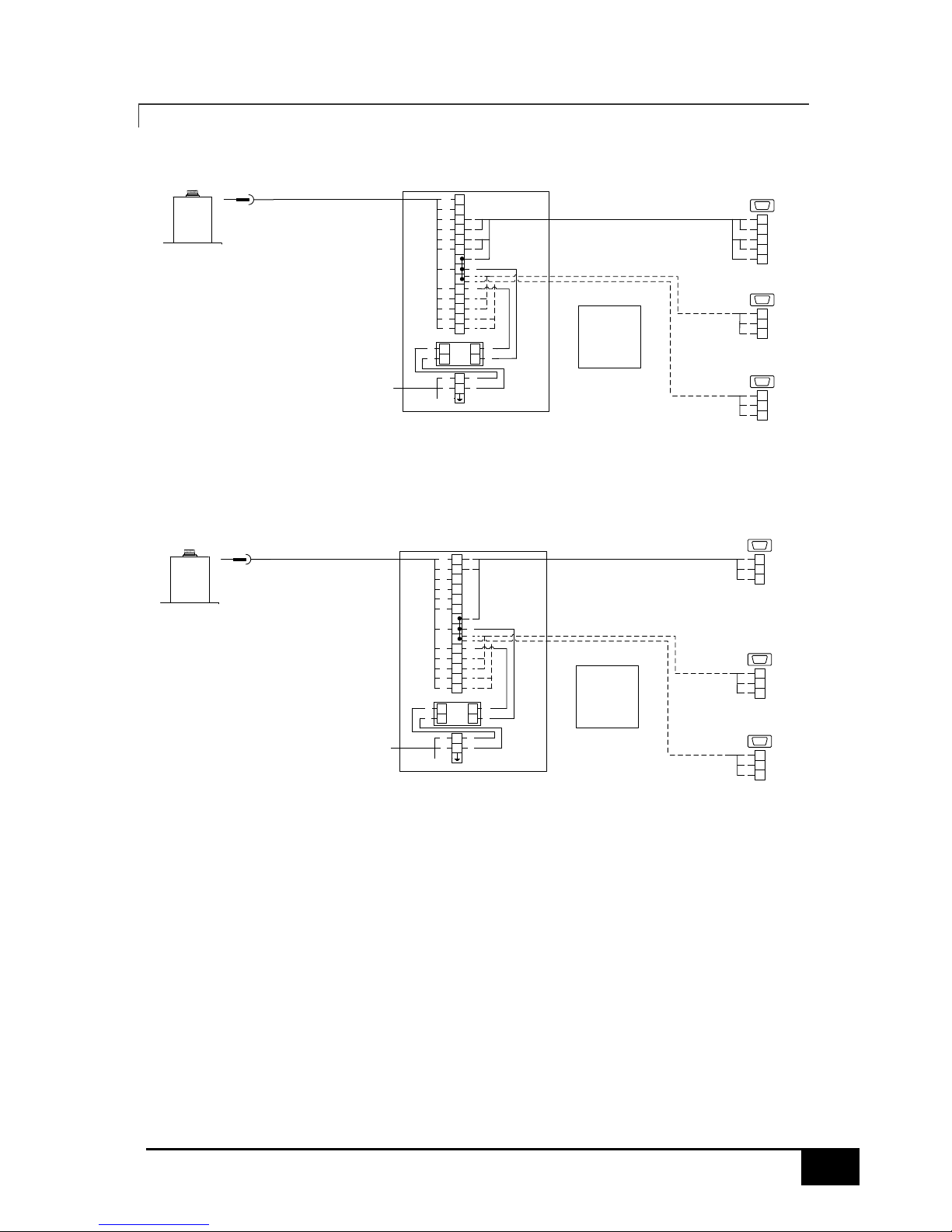
3.7.3 SURFACE MOTION SENSOR HARDWARE VERSION UP 8.4
IMU
Motion Sensor
1
2
3
4
5
6
-
-
+
RD
BR
OR
GR
PU
GY
PK
WH
L
N
GR/YE
BR
BL
2
1
3
4
110-220 VAC
5
JB
Motion Sensor
1
2
3
4
DB9, RS422
115 200, 8N1
1
2
3
4
55
AC/DC
PSU
+
-
BL
BR
L
N
12VDC110-220VAC
BL
BR
BK
WH
WH
BK
RS422
IMU
Motion Sensor
3
2
110-220 VAC
5
2
3
5
DB9, RS232
115 200, 8N1
2
3
5
RS232
-
7
8
9
10
YE
TR
BK
BL
2
3
2
3
5
5
2
3
5
DB9, RS232
4800, 8N1
2
3
5
2
3
5
DB9, RS232
4800, 8N1
2
3
5
Input 1
GPS or Heading input
Input 2
GPS or Heading input
GPS/Compass Input 1
RxD to Terminal 7
TxD to Terminal 8
Ground to Terminal -
GPS/Compass Input 2
RxD to Terminal 9
TxD to Terminal 10
Ground to Terminal -
1
2
3
4
5
6
-
-
+
RD
BR
OR
GR
PU
GY
PK
WH
L
N
GR/YE
BR
BL
JB
Motion Sensor
AC/DC
PSU
+
-
BL
BR
L
N
12VDC110-220VAC
BL
BR
BK
WH
WH
BK
-
7
8
9
10
YE
TR
BK
BL
2
3
2
3
5
5
2
3
5
DB9, RS232
4800, 8N1
2
3
5
2
3
5
DB9, RS232
4800, 8N1
2
3
5
Input 1
GPS or Heading input
Input 2
GPS or Heading input
GPS/Compass Input 1
RxD to Terminal 7
TxD to Terminal 8
Ground to Terminal -
GPS/Compass Input 2
RxD to Terminal 9
TxD to Terminal 10
Ground to Terminal -
29
IMU User Guide revision 3.1 SMC Ship Motion Control www.shipmotion.eu
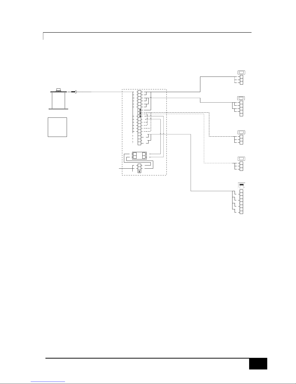
3.7.4 SURFACE MOTION SENSOR HARDWARE VERSION HIGHER THAN 8.5
GY--
-
IMU
Motion Sensor
RD
BR
PK
WH
GR/YE
BR
BL
WH/GN
WH/OR
OR
110-220 VAC
JB
Motion Sensor
OR/WH
AC/DC
PSU
BL
BR
15VDC110-220VAC
BL
BR
BK
WH
WH
BK
2
3
5
DB9, RS232
115 200, 8N1
5
YE
TR
BK
BL
2
3
2
3
5
5
DB9, RS232
4800, 8N1
2
3
5
DB9, RS232
4800, 8N1
GPS/Compass Input 1
RxD to Terminal 7
TxD to Terminal 8
Ground to Terminal -
GPS/Compass Input 2
RxD to Terminal 9
TxD to Terminal 10
Ground to Terminal -
GN
1
3
2
5
6
7
8
4
OR
GR/WH
BL
BL/WH
GR
BR/WH
BR
2
3
5
2
3
5
2
3
5
OR
GR
PU
3
2
3
2
2
1
4
3
5
1
2
5
DB9, RS422
115 200, 8N1
3
2
3433
1
2
3
4
5
6
+
7
8
9
10
11
12
13
14
N
L
-N
+L
WH/BK
WH/RD
WH/GN
WH/YE
30
IMU User Guide revision 3.1 SMC Ship Motion Control www.shipmotion.eu
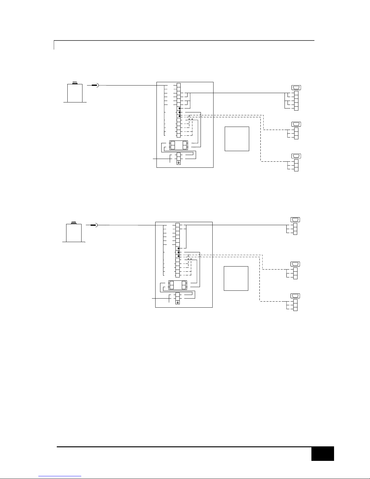
3.7.5 DEPTH RATED MOTION SENSOR
IMU
Motion Sensor
1
2
3
4
5
6
-
-
+
WH (2)
RD (3)
GN (4)
OR (5)
BL (6)
BL/BK (11)
BK/WH (12)
BK (1)
L
N
GR/YE
BR
BL
2
1
3
4
110-220 VAC
5
JB
Motion Sensor
1
2
3
4
DB9, RS422
115 200, 8N1
1
2
3
4
55
AC/DC
PSU
+
-
BL
BR
L
N
12VDC110-220VAC
BL
BR
BK
WH
WH
BK
RS422
IMU
Motion Sensor
3
2
110-220 VAC
5
2
3
5
DB9, RS232 Com11
115 200, 8N1
2
3
5
RS232
-
7
8
9
10
WH/BK (7)
RD/BK (8)
GN/BK (9)
OR/BK (10)
2
3
2
3
5
5
2
3
5
DB9, RS232
4800, 8N1
2
3
5
2
3
5
DB9, RS232
4800, 8N1
2
3
5
Input 1
GPS or Heading input
Input 2
GPS or Heading input
GPS/Compass Input 1
RxD to Terminal 7
TxD to Terminal 8
Ground to Terminal -
GPS/Compass Input 2
RxD to Terminal 9
TxD to Terminal 10
Ground to Terminal -
L
N
GR/YE
BR
BL
JB
Motion Sensor
AC/DC
PSU
+
-
BL
BR
L
N
12VDC110-220VAC
BL
BR
BK
WH
WH
BK
2
3
2
3
5
5
2
3
5
DB9, RS232
4800, 8N1
2
3
5
2
3
5
DB9, RS232
4800, 8N1
2
3
5
Input 1
GPS or Heading input
Input 2
GPS or Heading input
GPS/Compass Input 1
RxD to Terminal 7
TxD to Terminal 8
Ground to Terminal -
GPS/Compass Input 2
RxD to Terminal 9
TxD to Terminal 10
Ground to Terminal -
1
2
3
4
5
6
-
-
+
WH (2)
RD (3)
GN (4)
OR (5)
BL (6)
BL/BK (11)
BK/WH (12)
BK (1)
-
7
8
9
10
WH/BK (7)
RD/BK (8)
GN/BK (9)
OR/BK (10)
 Loading...