

SMC Networks IDU8E-10-C, IDU8E-10-K, IDU8E-10-L, IDU8E-10-R, IDU8E-10-S Operation Manual
...
IDX-OM-K031-E
Initial issue: September, 2006
5th edition: July, 2011
PRODUCT NAME
Refrigerated Air Dryer
MODEL /Series
IDU8E-10-C,K,L,R,S,TIDU8E-20-C,K,L,R,S,T
IDU11E-10-C,K,L,M,R,S,T IDU11E-20-C,K,L,M,R,T
IDU15E-10-C,K,M,R,S,T IDU15E-20-C,K,M,R,T
IDU8E-23-C,K,L,R,T,V
IDU11E-23-C,K,L,R,T,V
IDU15E-23-C,K,R,T,V
Please read this manual prior of using the air dryer. Keep the manual readily available for
reference.
© 2011 SMC CORPORATION All Rights Reserved

Dear Customers
Thank you for selecting SMC Refrigerated Air Dryer.
This operation manual must be read and understood thoroughly before using the product. It provides all essential
information pertaining to safety, as well as, maximizing product efficiency in order to extend the life of the product.
In addition, it is strongly recommended that you follow all the safety guidelines and re gulations set forth b y the
local government agency for proper installation and usage.
This manual explains about installation and trial operation of the product. These tasks should be performed only
by individuals with the proper training and have a good understanding of the air dryer .
There is no production amends or financial compensation due to dryers trouble.
This manual contains confidential inf ormation proprietary to SMC. It must not be repr oduced or disclosed to
others, or used in any other way, in part or in whole, except as authorized in writing by SMC.
Caution: Please under stand that the contents of this operation m anual are subjected to
change without prior notice.

Table of Contents
Table of Contents - 1
Table of Con tents
To Customers
Chapter i Safety Instructions
i - 1 Warning: Before Using Air Dryer.........................................................i - 1
i - 1 - 1 Hazard, Warning, and Caution Used in This Manual...........i - 1
i - 2 Danger Classifications/Position of Hazard warning Label........i - 2
i - 2 - 1 Danger Classifications..........................................................i - 2
i - 2 - 2 Hazard of Electricity..............................................................i - 3
i - 2 - 3 Hazard of Hot Surface...........................................................i - 3
i - 2 - 4 Hazard of Rotating Fan Motor...............................................i - 3
i - 2 - 5 Danger of Compressed A ir Circuit .......................................i - 3
i - 2 - 6 Positions of Hazard Warning Label......................................i - 4
i - 2 - 7 Hazard of Refrigerant............................................................i - 5
i - 2 - 8 Cautions about Usage...........................................................
i - 6
i - 2 - 9 Other Label ............................................................................
i - 6
i – 3 Disposal.......................................................................................................i – 7
i – 4 Limited warranty and Disclaimer / C ompliance R equi rements ......i - 8
Chapter 1 Parts Name and Functions
1 - 1 Parts Names and Functions................................................................ 1 - 1
Chapter 2 Transportation / Installation
2 - 1 Transportation..........................................................................................2 - 1
2 - 2 Installation.................................................................................................. 2 - 2
2 - 2 - 1 Location................................................................................2 - 2
2 - 2 - 2 Anchorage.............................................................................2 - 2
2 - 2 - 3 Air piping...............................................................................2 - 2
2 - 2 - 4 Drain Tube.............................................................................2 - 3
2 - 2 - 5 Electric Wiring ......................................................................2 - 4
2 - 3 Cautions about reinstallation.............................................................2 - 5
Chapter 3 Operation / Shutdown
3 - 1 Ch eck points before operation
.......................................................... 3 - 1
3 - 2 Operat ion.................................................................................................... 3 - 1
3 - 3 Shutdown................................................................................................... 3 - 2
3 - 4 Cautions about restart........................................................................... 3 - 2
3 - 5 C heck points before restart................................................................. 3 - 2
3 - 6 Precautions for long-term non-operation......................................3 - 2
Chapter 4 Maintenance
4 - 1 D aily inspect ion....................................................................................... 4 - 1
4 - 2 Periodical M aintenan ce .........................................................................4 - 1
4 - 2 - 1 Cleaning of ventilation grille (suction grille).......................4 - 1
4 - 2 - 2 Service parts.........................................................................4 - 1
4 - 2 - 3 Cleaning of the case assembly............................................4 - 1
4 - 2 - 4 Replacement of case assembly...........................................4 - 2
Chapter 5 Troubleshooting............................................................................................ 5 - 1
Chapter 6 References
6 - 1 Specifications........................................................................................... 6 - 1

Table of Contents
Table of Contents - 2
6 - 2 Dimensions................................................................................................ 6 - 2
6 - 3 Elect rical C ircuit...................................................................................... 6 - 3
6 - 4 Compressed Air and Refrigerant Circuit / Operation Principles.....6 - 5
6 - 5 H o w to order..............................................................................................6 - 6
Chapter 7 Option Specification C
7 - 1 Saf ety instructions.................................................................................. 7 - 1
7 - 2 Precautions for the installation and handling of the product .........7 - 1
7 - 3 Specifications........................................................................................... 7 - 1
Chapter 8 Specification for Option K
8 - 1 Saf ety instructions.................................................................................. 8 - 1
8 - 2 Specifications........................................................................................... 8 - 2
Chapter 9 Specification for Option L
9 - 1 Saf ety instructions.................................................................................. 9 - 1
9 - 2 Specification..............................................................................................9 - 1
9 - 3 Specification of heavy duty auto drain (A DH 4000- 04).............. 9 - 2
9 - 4 Installation of heavy duty auto drain............................................... 9 - 2
9 - 5 Maintenance.............................................................................................. 9 - 2
Chapter 10 Specification for Option M
10 - 1 Safety instructions................................................................................ 10 - 1
10 - 2 Specification............................................................................................10 - 2
10 - 3 Installation of the motor-type auto drain...................................... 10 - 3
Chapter 11 S p ecif icat ion for Option R
11 - 1 Safety instructions.................................................................................11 - 1
11 - 2 Specifications of the GFCI..................................................................11 - 2
11 - 3 How to connect the power supply...................................................11 - 2
Chapter 12 Specification for Option S
12 - 1 Safety instructions................................................................................ 12 - 1
12 - 2 Specifications......................................................................................... 12 - 1
12 - 3 How to connect the power supply cable...................................... 12 - 1
12 - 4 Electric circuit......................................................................................... 12 - 2
Chapter 13 Specification for Option T
13 - 1 Safety instructions................................................................................ 13 - 1
13 - 2 Specifications......................................................................................... 13 - 1
13 - 3 Remote operation.................................................................................. 13 - 2
13 - 4 How to connect the power supply and signal cable................ 13 - 2
13 - 5 Electric circuit......................................................................................... 13 - 3
Chapter 14 Specification for Option V
14 - 1 Safety instructions................................................................................ 14 - 1
14 - 2 Specifications......................................................................................... 14 - 2
14 - 3 How to perform maintenance...........................................................14 - 2
Chapter 15 Service Record
15 - 1 Service Record.......................................................................................15 - 1
i Safety Instructions
i Safety Instructions
Be sure to read and comprehend important cautionary
notifications in this operation manual before use
Do not operate the product without the cover panel.
i-1 Warning: Before Using Air Dryer
In this chapter, the stated contents are espec ially abo ut safety.
This Air Dryer is installed downstream of the air compressor to remove moisture. The manufacturer is not
responsible for an y misus es or mis applications .
This air dryer oper ates with high vo ltage and hot sur faces during oper ation. I n addition, t his air dryer
has high speed rotating fan and motor, which can cause serious inj ury upon accidental contact. It is
advised that you contact the factory or SMC autho rized dealer f or spare parts or other s ervicing needs.
We strongly recommend that any one who is working with this air dryer need to read and understand the
instructions in th is m anu al bef orehand. Often, it’s nec essar y for t he peop le in volved, to r ecei ve tra ining
in order to address the issues of safety and pr oper applic ation.
When short period power s hortage (i nclu ding instantly recovered shortage) is r ecover e d, it may take a
longer starting period th an usual startin g or ma y not start due to the protective devices.
In this case, turn off the ON-OFF switch with lamp on dryer panel and wait 3 minutes. After this step, turn
on the switch to restart. Whenever open the cover panel of this unit, do no t m iss to turn off the ON- OFF
switch with lamp, bec ause dryer m ay start itself when t he power supp ly is rec overed.
Connections to a power source where the product is exposed to transient stresses exceeding
overvoltage c ategor y II (as def ined in I EC60664- 1).
Only connect to TN-S power distribution systems with N conductively connected to PE.
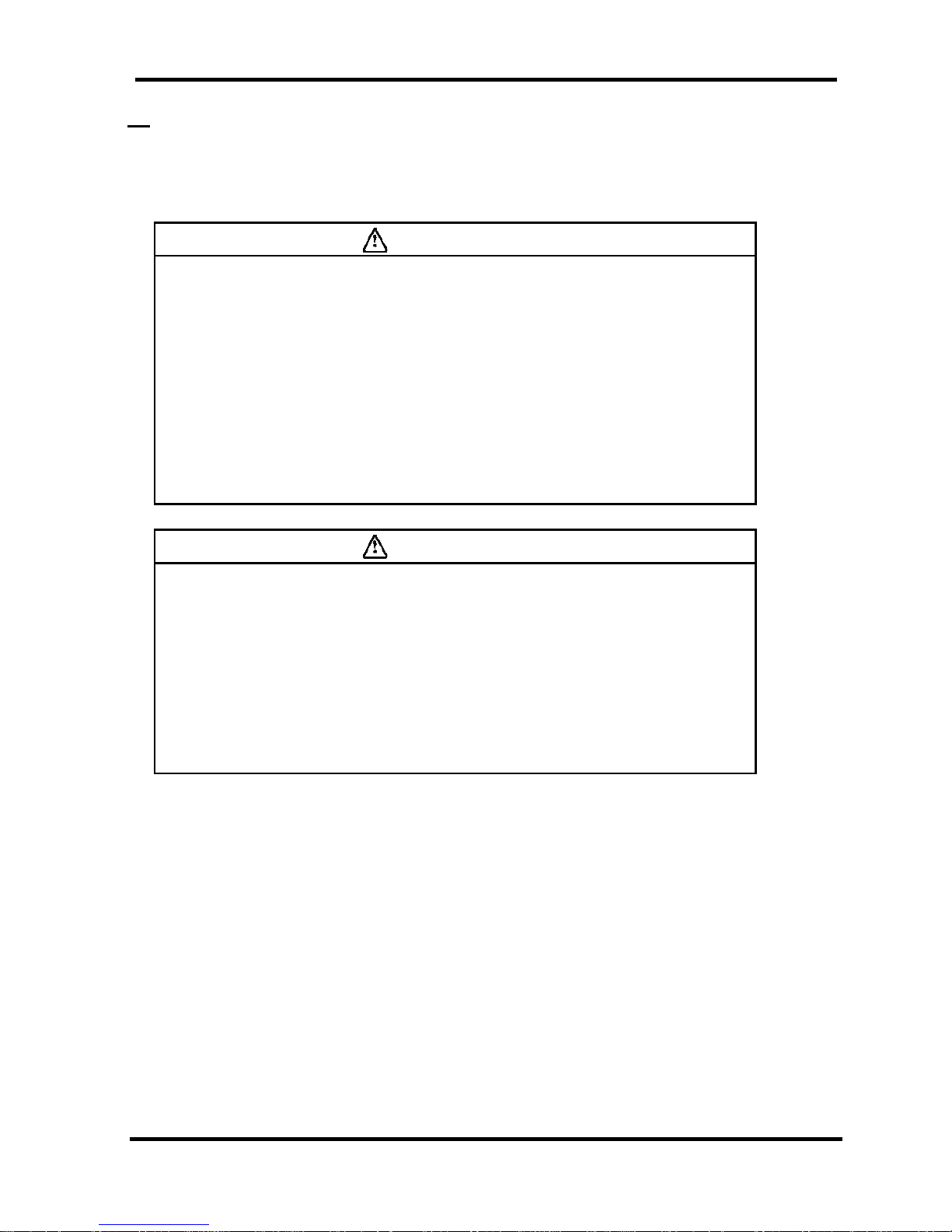
i-1-1 Hazard, Warning, and Caution Used in This Manual
This product is designed with th e first priorit y on safet y. However, there are some i nherent risks
that cannot be elim inated. This m anual classifies these risk s into the following three categories
according to the severity: DANGER, WARNING and CAUTION. Read the warning statements
carefully and thoroughly understand them before operating or performing maintenance on the unit.
DANGER
“DANGER” indicates that there is an imminenc e hazard that w ill cause serious
injury or death if not avoided.
WARNING
“WARNING” indicates that there is a hazard that may cause serious injury or
death if not avoided.
CAUTION
“CAUTION” indicates t hat there is a hazard that may cause mino r injury.
i - 1
i Safety Instructions
i-2 Danger Classifications & Position of Hazard warning Labels
To help you recognize the hazards, the unit utilizes special graphics to indicate different hazards. Confirm the
contents of the hazards and the location of the labels before operation.
Warning
• Only properly trained, qualified personnel are allowed to perform tasks such as:
Operation, installation, relocation of product and maintenance works.
• Should any problem occurs, address it according to instruction in this manual.
• Identify problems following the guidelines in Chapter 5 for Troubleshooting before
proceed with maintenance works.
• The product should not be turn on in the event of any problems.
When the product gets out of order, shutdown immediately, and contact for
service
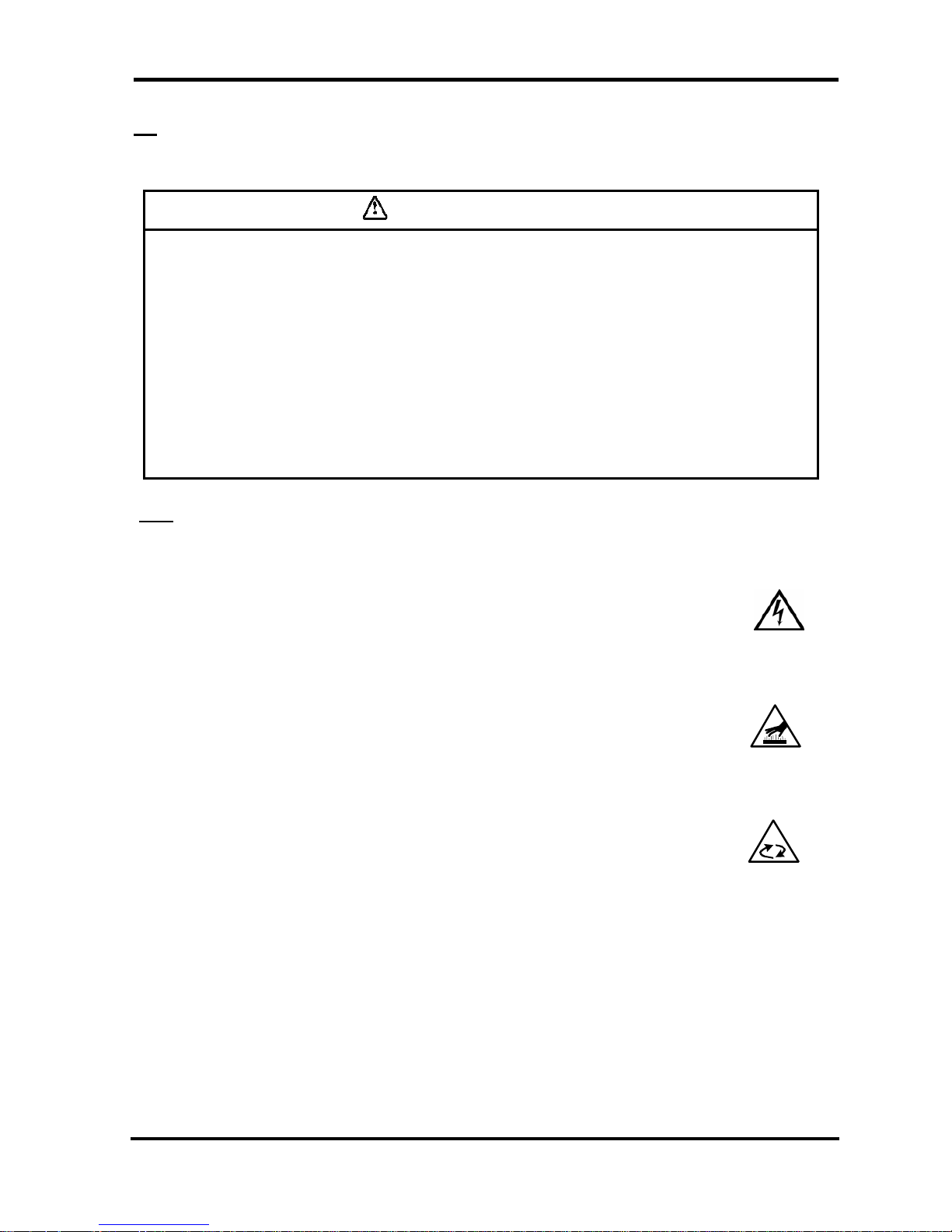
i-2-1 Danger Classifications
Specific danger classification of this product is as follows.
Hazard of Electricity
Since this product operates with high voltage, there is the danger of electric
shock. This special symbol is used, along with key words: “CAUTION”, “WARNING”
or “DANGER”, on the product and in this manual.
Hazard of Hot Surface
Since this product becomes hot while running, there is the danger of burn injury.
This special symbol is used, along with key words: “CAUTION”, “WARNING” or
“DANGER”, on the product and in this manual.
Hazard of Rotor
Since this product has parts that rotate at high speed while running, there is the
danger of bodily injury. This special symbol is used, along with key words: “CAUTION”,
“WARNING” or “DANGER”, on the product and in this manual.
i - 2
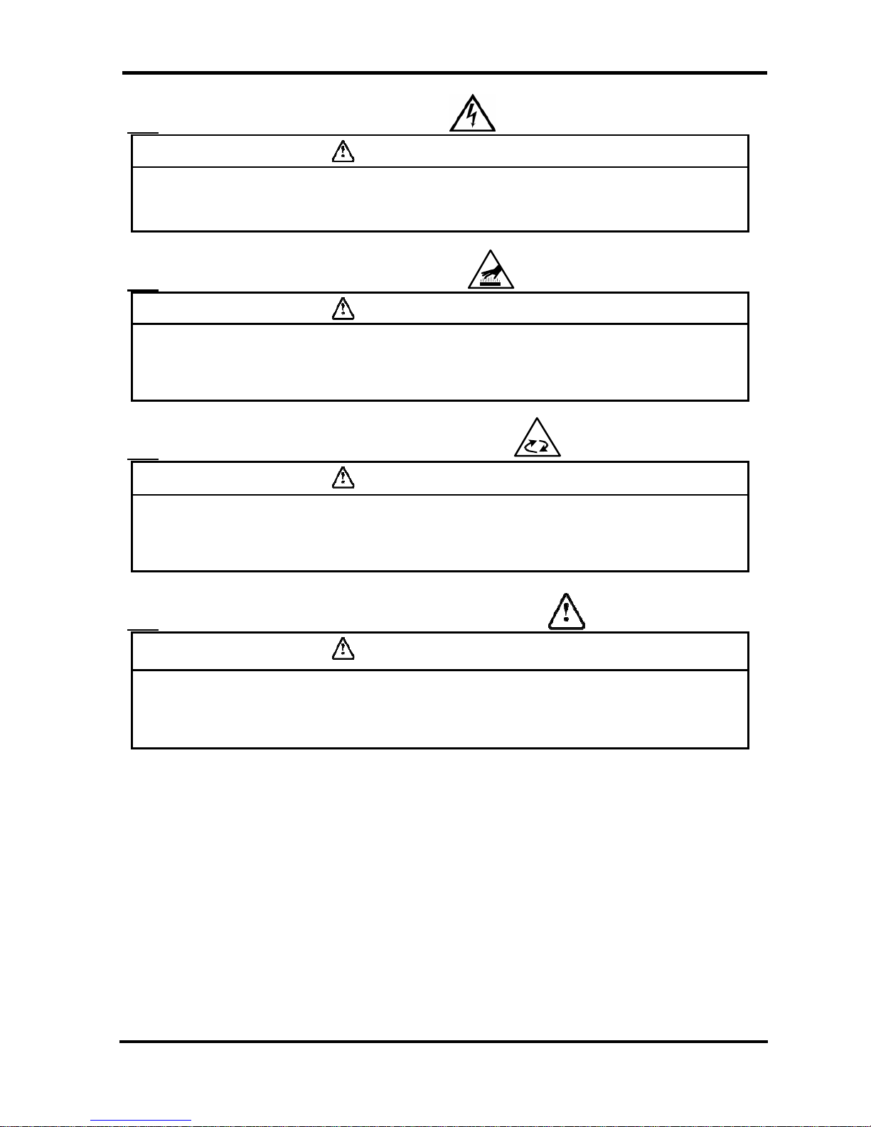
i Safety Instructions
i-2-2 Hazard of Electricity
Warning
Inside of this product, there is a power-supplying section with high voltage separated
by the cover panel. Do not operate the product with the cover panel off.
i-2-3 Hazard of Hot Surface
Warning
Since this product has parts that become hot during operation, there is the danger of
burn-associated injuries. These parts remain hot even after power is off. Wait until the
unit has cooled down before touching.
i-2-4 Hazard of Rotating Fan Motor
Warning
Since this product has parts that rotate during operation, there is the danger of injury
resulting from direct contact. The fan and rotor will start/stop automatically. Thus, do
not work on them when power is on.
i-2-5 Danger of Compressed Air Circuit
Warning
Before replacing or cleaning p a rt s , be sure to relief the pressure re mained insid e of the
product until the gauge indicates “0”. High pressure can propel object at high velocity
and cause injury.
i - 3
i Safety Instructions
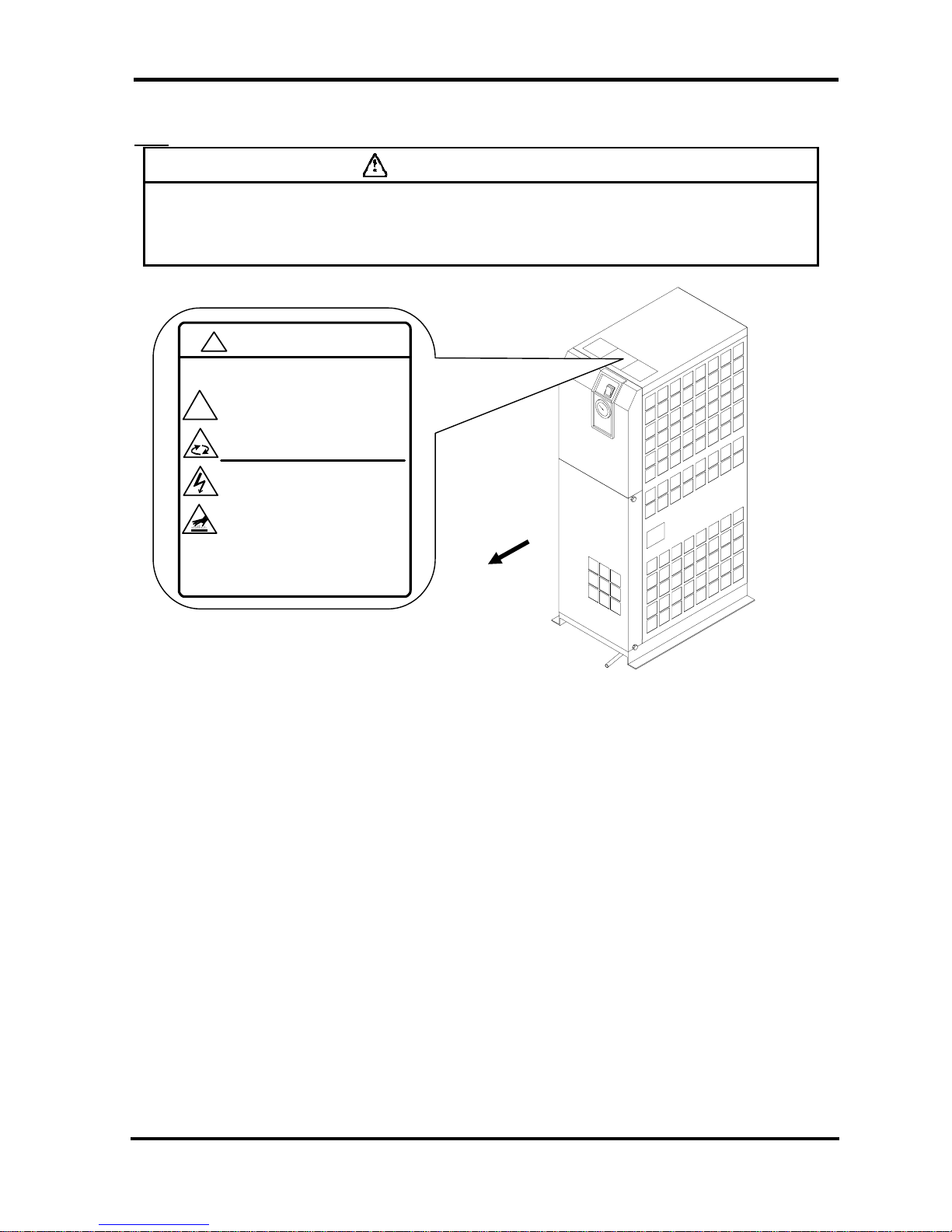
i-2-6 Positions of Danger Warning Label
Warning
Read with caution and pay attention to the notations of danger warning labels.
Do not remove or rub danger warning labels.
Confirm the positions of danger warning labels.
Front
WARNING 警告
!
1 Remove panels for maintenance only.
2 Never insert anything into product to ensure
safety.
3 Cut power prior to maintenance to prevent
electric shock.
4 Settle product to room temp.before main tenance toprevent burn or frostbite.
5 Ensure zero air pressure before replacing parts.
1 点検以外はパネルを取り外さないこと。
2 回転物があるので指、棒状の物を差し
込まないこと。
3 感電の恐れがあるので、点検の前には電源を
切ること。
4 火傷の恐れがあるので、点検の前には装置を
常温にすること。
5 部品交換の前には必ず、空気圧力を"0"に
すること。
!
i - 4
i Safety Instructions
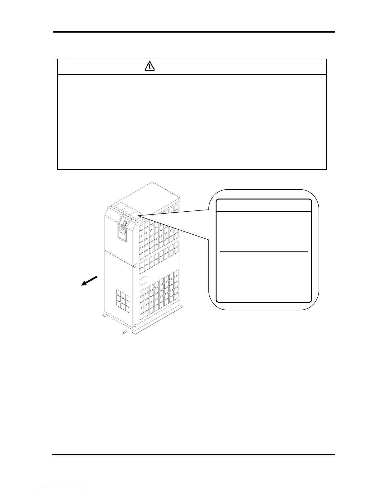
i-2-7 Hazard of Refrigerant
Caution
This product uses Fluorocarbon (HFC) as a refrigerant.
It is strictly forbidden to emit Fluorocarbon into the atmosphere. Before you repair the
refrigerant circuit, you should collect the refrigerant with proper evacuation system.
The collected refrigerant should be properly recycled by qualified agency. Only
personnel with proper credential are allowed to handle refrigerant.
Only properly trained qualified personnel are allowed to remove the cover panel of the
product.
The quantity and the type of Fluorocarbon are mentioned on the specification label.
See Page i - 6.
Fluorocarbon Collection an d Destruction La w in Japan
フロン回収破壊法第一種特定製品
This product uses
Fluorocarbon (HFC) as a refrigerant.
1 It is strictly forbidden to emit Fluorocarbon
to the atmosphere.
2 When disposing this product, Fluorocarbon
must be collected in an appropriate manner.
3 The kind of Fluorocarbon and the amount used
in this product is prited on the name label.
この製品には冷媒として、
フロン類(HFC)が使われています。
1 フロン類をみ だりに大気中に放出することは
禁じられています。
2 この製品を廃棄する場合には、フロン類の回収が
必要です。
3 フロン類の種類及び数量は、型式銘板に記載
されています。
Front
i - 5
i Safety Instructions
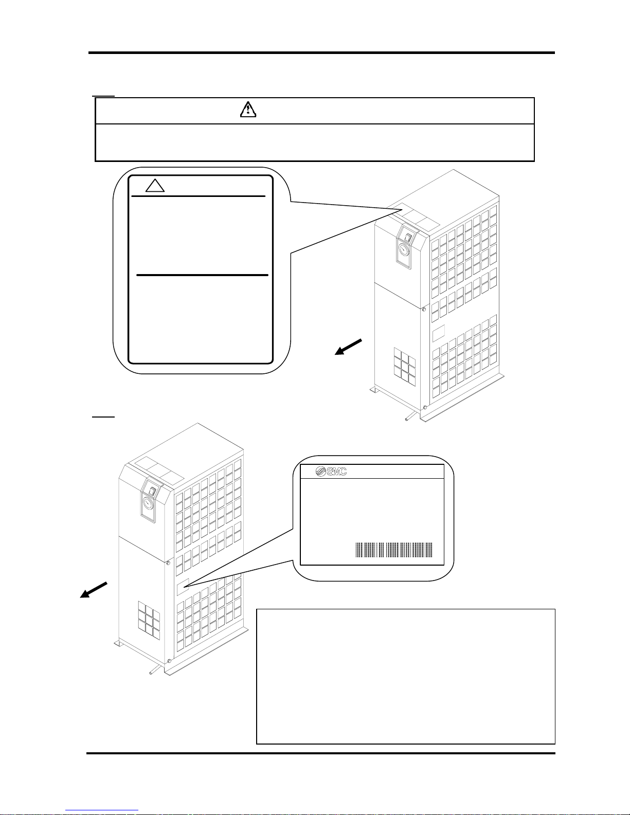
i-2-8 Cautions about Usage
Warning
Please follow the instructions on all warning labels. Do not remove or deface
warning labels , an d confirm the loca tion of warning la b e ls.
i-2-9 Other Label
Front
Contents
MODEL: Model
VOLTAGE: Power supply voltage (frequency)
RUNNING CURRENT: Running current
REFRIGERANT: Type of refrigerant (amount)
WEIGHT : Weight MAX.PRESS: Maximum operating p res s ur e
SERIAL No.: Serial No.
MAKER: Maker
MADE IN: Country of manufacture
S
p
ecification Label
AIR DRYER
MODEL
VOLTAGE
RUNNING CURRENT
REFRIGERANT
WEIGHT MAX.PRESS.
SERIAL No.
MAKER
MADE IN
CAUTION 注意
!
1 Read manual b efore oper a tion.
2 Ensure vantilation and maintenance
space.
3 Keep water away from the product.
4 Secure In / Out connector with spanner
during piping.
5 Wait 3 minutes befor e r e star t.
6 Ensure Running Condition / Evaporating
Tem p. in g r ee n z one .
1 ご使用前に必ず取扱説明書を読んでください。
2 通風、メンテナンススペースを確保して
ください 。
3 雨や水滴がかからないようにしてください。
4 IN/OUTポートをスパナで固定して
配管 して ください。
5 再起動は運転停止3分後に行ってください。
6 R UN NING C OND ITIO N・蒸 発 温度 計は
グリーン帯で使用してください。
Front
i - 6
i Safety Instructions
i-3 Disposal
When you dispose of the product, you should collect the refrigerant and the refrigerant oil inside the refrigerant
circuit.
Caution
This product contains Fluorocarbon HFC.
It is strictly forbidden to emi t Fluoroc arbo n in to the at mosphere. Bef ore you
repair the refrigerant circuit, you should collect the refrigerant with proper
evacuation system. The collected refrigerant should be properly recycled by
qualified agency. Only personnel with proper credential are allowed to
handle refrigerant.
Only properly trained and qualified personnel are allowed to remove the
cover panel of the product.
The quantity and the type of Fluorocarbon are mentioned on the
specification label. See Page i - 6.
Caution
Dispose of the refriger ant and refrigerant oil according to the regulation of
local government.
Only personnel wit h proper credential are all owed to collect ref rigerant and
refrigerant oil.
Only properly trained and qualified personnel are allowed to remove the
cover panel of the product.
For any questions, please co ntact our factory or SMC authorized dealers.
i - 7
i Safety Instructions
i – 4 Limited warranty and Disclaimer / Compliance Requirements
The product used subject to the following “Limited warranty and Disclaimer“ and “Compliance Requirements.
Read and accept them before using the product.
Limited warranty and Di scl aimer
1. The warrant y per i od of t he pro d uc t is 1 yea r i n s er v ice or 1.5 years after th e pr od uc t is de l i vered.
Also, the product may have specified durability, running distance or replacement parts. Please consult
your neares t sa l es branch.
2. For any failure or damage reported within the warranty period which is clearly our responsibility, a
replacement product or necessary parts will be provided.
This limited warranty applies only to our product independently, and not to any other damage incurred
due to the failure of the product.
3. Prior to using SMC products, please read and understand the warranty terms and disclaimers noted in
the specified catalog for the particular products.
Compliance Requirements
1. The use of SMC products with production equipment for the manufacture of weapons of mass
destruction (WMD) or other weap on is s tr ic t ly prohibited.
2. The exports of S MC pr odu cts or tec hno lo g y from one cou ntr y to anot her are go vem ed b y the r ele van t
security laws and regulation of the countries involved in the transaction. Prior to the shipment of a SMC
product of a SMC produ ct to ano ther country, assure that all local rule s gove ming t hat e xport are known
and followed.
Caution
The Product is provided use in manuf actu rin g ind ust rie s.
The product herein described is basically provided for peaceful use in manufacturing industries.
If considering using the product in other industries, consult SMC beforehand and exchange
specifications or a contact if necessary.
If anything is u nc l ear, contact your nearest sales br an ch .
i - 8
1 Name and Functions Parts
1 Parts Name and Functions
1-1
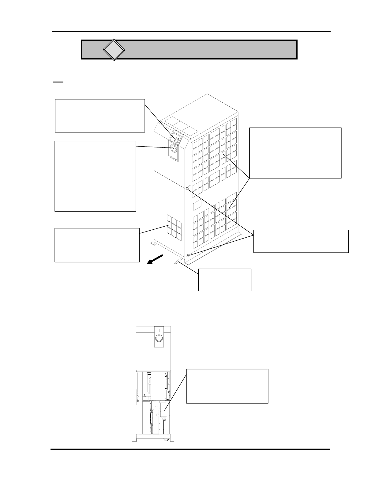
Parts Name and Functions
• IDU8E to 15E
Front
The lamp is continuously ON
during normal operation.
Evaporation Thermometer
Indicates the evaporating
temperature of refrigerant on
low-pressure side.
During normal operation, the
indicator remains in the
green zone.
Panel Lock (2x2)
Another two are on opposite side
Right Side Ventilation Grille
(Outlet)
Waste heat will be exhausted as
hot air by the fan motor. Do not
block with wall and so on.
Inspection Grille
Confirm the discharge of drain
from this grille once a day.
Drain Tube
Discharges drain.
Switch with Lamp
V
iew with Front Panel removed
Do not remove the insulation
on the auto drain.
Aut o Drain
1 - 1
1 Name and Functions Parts
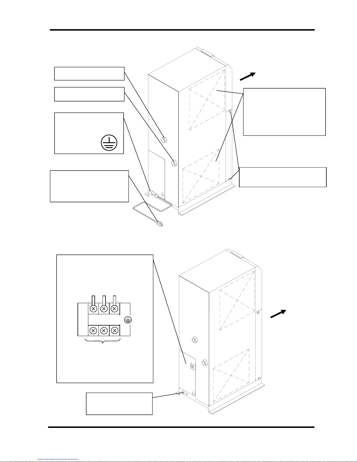
• IDU8E to 15E-10 (AC100V)
Front
Air Outlet (OUT)
Screw for the Earth
Connect the earth to this
screw
Power Cord
Insert the plug to an out let fo r
exclusive use of AC100V.
Air Inlet (IN)
Panel Lock (2x2)
Another two are on opposite side
Left Side V entilation Grille
(Inlet)
Breathe in cooling air from this
grill. Do not bung up with wal l
and so on.
・
IDU8E to 15E-20 (AC200V)
・ IDU8E to 15E-23 (AC230V)
Rear Panel
Y ou can see th e terminal blo ck when y ou
remove this cover. Connect the power
cable through the membrane grommet
.
Rubber Grommet
(Width 6.5mm and below)
(Screw head dimension: 0.25” (6.5mm)
Customer Connection Side
Terminal Connecting Screw: M3
Ring terminals: 1.25-3
L
N
PE
( )
Power cable inlet
Front
1 - 2
2 Transportation / Installation
2 Transportation / Installation
Warning
• Only properly trained, qualified personnel are allowed to perform tasks such as:
Operation, installation, relocation of product and maintenance works.
• Strongly recommend to prepare the spare dryer when applying the dryer for
important product or system.
2-1 Transportation
When you transport the product, you should fol lo w the instr uctio ns belo w:
• You should lift the product from the base surface with careful attention to prevent tipping over.
• Do not lay the product sideways, or you will damage the product.
• Do not suspend the product from the ceiling or hang from the wall.
• Do not transport the product with a ny part suc h as an air filter m ounted on the f ittings at the air in let or
outlet port of the product. If it is unavoidable to transport the product with such a part mounted, support
the mounted part with a bracket to prevent the product from being affected by vibration during
transportation.
Warning
This product is a heavy object and will give a danger when transported. Be sure to
keep the above instructions.
The IDU8E to 15E weigh 44 to 71kg. Three people for the IDU8E and 11E and four
people for IDU15E, or a tool like a fork lift must be prepared.
2 - 1

2 Transportation / Installation
2-2 Installation
2-2-1 Location
The product should not be used or stored in the following conditions: Those conditions will cause
not only malfunction but also failures.
• Environment where the product is exposed to
rainwater, moisture, salt water or oil.
• Locations where the product is exposed to dust
or particles
• Locations where the product is exposed to
flammable, combustible or explosiv e fum es.
• Locations where the product is exposed to
corrosive gas or solvent.
•
Locations where the product is exposed to
direct sunlight or radiated heat.
•
Locations where ambient temperature is
beyond following range:
•
On-stream: 2 to 40oC
• Storage: 0 to 50oC (when there is no drain
water inside of the piping)
•
Locations where temperature changes rapidly.
• Locations where strong electromagnetic noise
is generated.
•
Circumstances where static electricity is
produced or discharged thro ugh the body o f the
product
•
Locations where strong high frequency shock
wave is generated
•
Locations where danger of thunder is apparent.
• Locations where loading on vehicles, marine
vessels, and so on
• Locations where altitude is higher than 2,000
meters
• Circumstances where strong vibration or impact
are transmitted.
• Circumstances where too much force and weight
are put on the body of the product that causes it to
deform.
•
Circumstances where not enough clearance
spaces to do maintenance
• Spaces needed for maintenance
• Front : 600mm
• Rear : 600mm
• Top : 600mm
• ight : 600mm
• Left : 600mm
• Locations where ventilation grille of the product can
be blocked.
•
Locations where the dryer could intake warm air (for
example from a compressor or other dryers).
2-2-2 Anchorage
• The air dryer should be installed on a vibration-free, stable, horizontal flat surface.
• Refer to “Chapter6 6-2 Dimensions” for the dimensions.
• IDU8E~15E should be bolted by anchor bolts to prevent falling. We recommend the anchor bolt sets that
we are selling separately as accessories.
2-2-3 Air piping
• Connection to the inlet and outlet of compressed air should be made removable by using union and so on.
• Pressing the hexagonal fitting with screw wrench and so on, connect the air piping fittings to the body.
• When mounting any part such as an air filter on the fitting at the compressed air inlet or outlet port, support the
part to prevent excessive force from being applied to the product.
• Be careful not to let the vibration of the air compressor transmit.
2 - 2
 Loading...