

IDX-OM-K021
Initial issue October, 2006
Rev.F:Feb,2017
PRODUCT NAME
Refrigerated Air Dryer
MODEL / Series
IDFB22E-11 IDFB22E-11 - A,K,R,S,T,V
IDFB22E-23 IDFB22E-23 - A,K,R,T,V
IDFB37E-23 IDFB37E-23 - A,K,R,T,V
IDFB55E-46 IDFB55E-46 - A,L,R,T,V
IDFB75E-46 IDFB75E-46 - A,L,R,T,V
Please read this manual prior of using the air dryer. Keep the manual readily available for
reference.
© 2017 SMC CORPORATION All Rights Reserved.

To Customers
Thank you for selecting SMC Refrigerated Air Dryer.
This operation manual must be read and understood thoroughly before using the equipment. It provides all
essential information pertaining to safety, as well as, maximizing equipment efficiency in order to extend the life of
the equipment.
In addition, it is strongly recommended that you follow all the safety guidelines and regulations set forth by the
local government agency for proper installation and usage.
This manual explains about installation and trial operation of the equipment. These tasks should be performed
only by individuals with the proper training and have a good understanding of the air dryer.
There is no production amends or financial compensation due to dryers trouble.
This manual contains confidential information proprietary to SMC. It must not be reproduced or disclosed to
others, or used in any other way, in part or in whole, except as authorized in writing by SMC.
Caution: Please understand that the contents of this operation manual are subjected to
change without prior notice.

Table of Contents
Table of Contents - 1
Chapter i Safety Instructions
i - 1 Warning: Before Using Air Dryer ................................................................. i - 1
i - 1 - 1 Hazard, Warning, and Caution Used in This Manual ..................................... i - 1
I - 2 Danger Classifications/Position of Hazard warning Label ....................... i - 2
i - 2 - 1 Danger Classifications .................................................................................... i - 2
i - 2 - 2 Hazard of Electricity ....................................................................................... i - 3
i - 2 - 3 Hazard of Hot Surface .................................................................................... i - 3
i - 2 - 4 Hazard of Rotating Fan Motor ........................................................................ i - 3
i - 2 - 5 Danger of Compressed Air Circuit .................................................................. i - 3
i - 2 - 6 Positions of Hazard Warning Label ................................................................ i - 4
i - 2 - 7 Hazard of Refrigerant ..................................................................................... i - 5
i - 2 - 8 Cautions about Usage .................................................................................... i - 6
i - 2 - 9 Other Label ..................................................................................................... i - 6
i - 3 Disposal ........................................................................................................ i - 8
i - 4 Limited warranty and Disclaimer / Compliance Requirements............... i - 9
Chapter 1 Parts Name and Functions
1 - 1 Parts Names and Functions ..................................................................... 1 - 1
Chapter 2 Transportation / Installation
2 - 1 Transportation ............................................................................................ 2 - 1
2 - 2 Installation .................................................................................................. 2 - 2
2 - 2 - 1 Location ........................................................................................................ 2 - 2
2 - 2 - 2 Tie Down ...................................................................................................... 2 - 3
2 - 2 - 3 Air piping ...................................................................................................... 2 - 3
2 - 2 - 4 Drain Tube .................................................................................................... 2 - 3
2 - 2 - 5 Electric Wiring .............................................................................................. 2 - 4
2 - 3 Cautions for Reinstallation ......................................................................... 2 - 6
Chapter 3 Operation / Shutdown
3 - 1 Check points before operation ................................................................. 3 - 1
3 - 2 Operation .................................................................................................... 3 - 1
3 - 3 Shutdown .................................................................................................... 3 - 2
3 - 4 Cautions about restart ............................................................................... 3 - 2
3 - 5 Check points before restart ....................................................................... 3 - 2
3 - 6 Precautions for long-term non-operation ................................................ 3 - 2
Chapter 4 Maintenance
4 - 1 Daily inspection .......................................................................................... 4 - 1
4 - 2 Periodical maintenance ............................................................................. 4 - 1
4 - 2 - 1 Cleaning of ventilation grille (suction grille) .................................................. 4 - 1
4 - 2 - 2 Service parts ................................................................................................. 4 - 1
4 - 2 - 3 Cleaning of the case assembly ..................................................................... 4 - 1
Table of Contents

Table of Contents
Table of Contents - 2
Chapter 5 Troubleshooting
5 - 1 Cause and countermeasure of errors ...................................................... 5 - 1
5 - 2 How to reset the thermal relay and high pressure switch
(Only IDFB55E, 75E) .......................................... 5 - 3
Chapter 6 References
6 - 1 Specifications ............................................................................................. 6 - 1
6 - 2 Refrigerant with GWP reference ............................................................... 6 - 2
6 - 3 Dimensions ................................................................................................. 6 - 2
6 - 4 Electrical Circuit ......................................................................................... 6 - 4
6 - 5 Compressed Air and Refrigerant Circuit / Operation Principles ...........6 – 5
Chapter 7 References for Option A
7 - 1 Safety instructions ..................................................................................... 7 - 1
7 - 2 Specifications ............................................................................................. 7 - 1
7 - 3 Air piping ..................................................................................................... 7 - 1
7 - 4 Air flow capacity ......................................................................................... 7 - 1
7 - 5 Compressed Air and Refrigerant Circuit / Operation Principles ........... 7– 2
Chapter 8 Specification for Option K
8 - 1 Safety instructions ...................................................................................... 8 -1
8 - 2 Specifications .............................................................................................. 8 -1
Chapter 8 Specification for Option L
9 - 1 Safety instructions ..................................................................................... 9 - 1
9 - 2 Specifications ............................................................................................. 9 - 1
9 - 3 Specification of heavy duty auto drain (ADH4000-04) ............................ 9 - 2
9 - 4 Maintenance................................................................................................ 9 - 2
Chapter 10 Specification for Option R
10 - 1 Safety instructions ................................................................................... 10 - 1
10 - 2 Specifications of the GFCI ....................................................................... 10 - 1
10 - 3 How to connect the power supply .......................................................... 10 - 1
10 - 4 Cautions for handling the GFCI .............................................................. 10 - 3
10 - 5 Electric circuit ........................................................................................... 10 - 3
Chapter 11 Specification for Option S
11 - 1 Safety instructions .................................................................................... 11 - 1
11 - 2 Specifications ............................................................................................ 11 - 1
Chapter 12 Specification for Option T
12 - 1 Safety instructions .................................................................................... 12 -1
12 - 2 Specifications ............................................................................................ 12 -1
12 - 3 Remote operation ...................................................................................... 12 -2
12 - 4 How to connect the power supply and signal cable .............................. 12 -2
12 - 5 How to re-start the operation ................................................................... 12 -3
12 - 6 Electric wiring diagram ............................................................................. 12 -4

Table of Contents
Table of Contents - 3
Chapter 13 Specification for Option V
13 - 1 Safety instructions .................................................................................... 13 -1
13 - 2 Specifications ............................................................................................ 13 -1
13 - 3 How to perform maintenance................................................................... 13 -2
13 - 4 Electric circuit ............................................................................................ 13 -2
Chapter 14 Service Record
14 - 1 Service Record .......................................................................................... 14 -1
Air Dryer i Safety Instructions
i-2Danger Classifications & Position of Hazard warning Labels
i - 2
IDX-OM-K021
i-2 Danger Classifications & Position of Hazard warning Labels
To help you recognize the hazards, the unit utilizes special graphics to indicate different hazards. Confirm the
contents of the hazards and the location of the labels before operation.
Warning
Only properly trained, qualified personnel are allowed to perform tasks such as:
Operation, installation, relocation of equipment and maintenance works.
Should any problem occurs, address it according to instruction in this manual.
Identify problems following the guidelines in Chapter 5 for Troubleshooting before
proceed with maintenance works.
The equipment should not be turn on in the event of any problems.
When the equipment gets out of order, shutdown immediately, and contact for
service
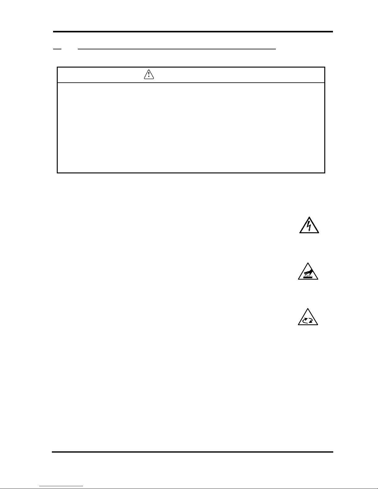
i-2-1 Danger Classifications
Specific danger classification of this equipment is as follows.
Hazard of Electricity
Since this equipment operates with high voltage, there is the danger of electric
shock. This special symbol is used, along with key words: “CAUTION”, “WARNING”
or “DANGER”, on the equipment and in this manual.
Hazard of Hot Surface
Since this equipment becomes hot while running, there is the danger of burn injury.
This special symbol is used, along with key words: “CAUTION”, “WARNING” or
“DANGER”, on the equipment and in this manual.
Hazard of Rotor
Since this equipment has parts that rotate at high speed while running, there is the
danger of bodily injury. This special symbol is used, along with key words: “CAUTION”,
“WARNING” or “DANGER”, on the equipment and in this manual.
IDFB Series
Air Dryer i Safety Instructions
i-2Danger Classifications & Position of Hazard warning Labels
i - 3
IDX-OM-K021
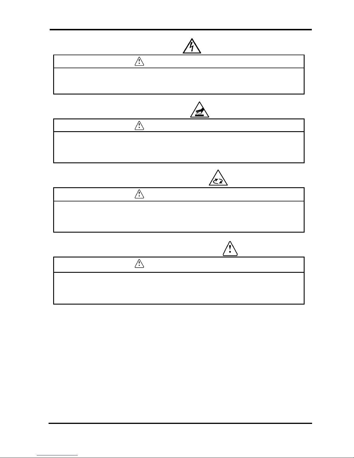
i-2-2 Hazard of Electricity
Warning
Inside of this equipment, there is a power-supplying section with high voltage
separated by the cover panel. Do not operate the equipment with the cover panel off.
i-2-3 Hazard of Hot Surface
Warning
Since this equipment has parts that become hot during operation, there is the danger
of burn-associated injuries. These parts remain hot even after power is off. Wait until
the unit has cooled down before touching.
i-2-4 Hazard of Rotating Fan Motor
Warning
Since this equipment has parts that rotate during operation, there is the danger of
injury resulting from direct contact. The fan and rotor will start/stop automatically.
Thus, do not work on them when power is on.
i-2-5 Danger of Compressed Air Circuit
Warning
Before replacing or cleaning parts, be sure to relief the pressure remained inside of the
equipment until the gauge indicates “0”. High pressure can propel object at high
velocity and cause injury.
IDFB Series
Air Dryer i Safety Instructions
i-2Danger Classifications & Position of Hazard warning Labels
i - 4
IDX-OM-K021
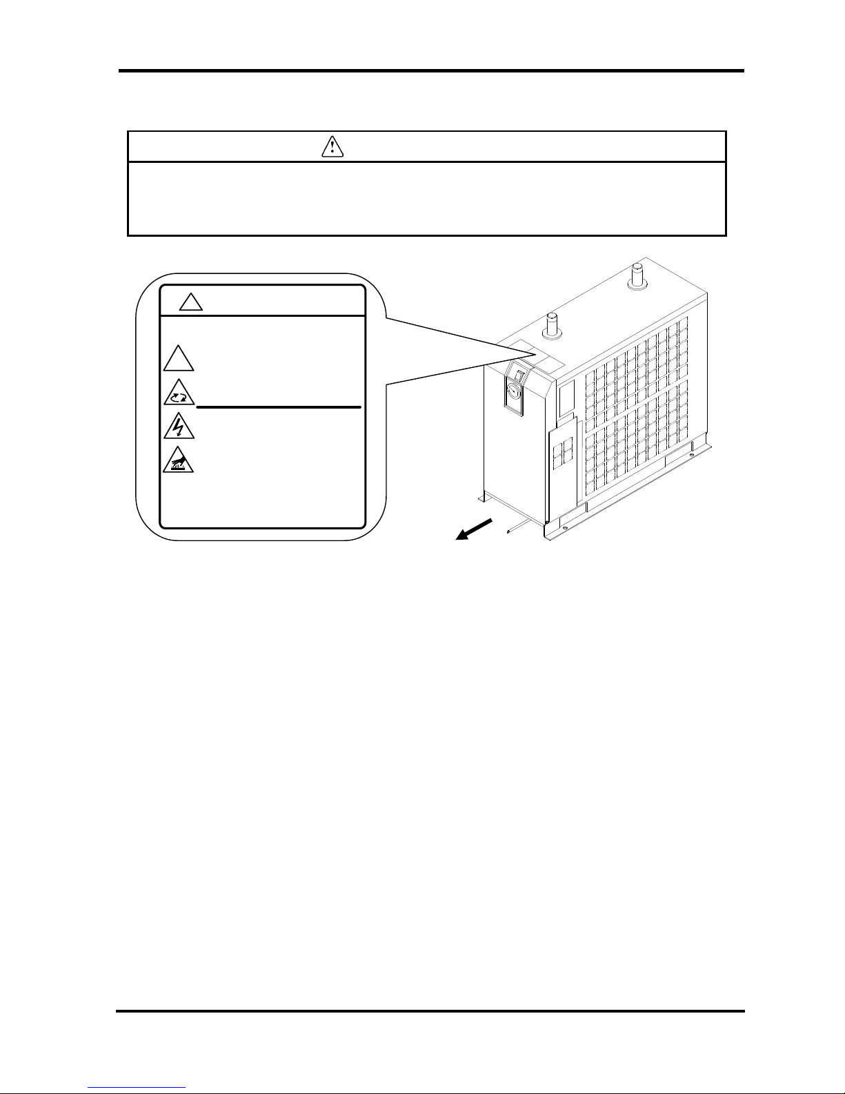
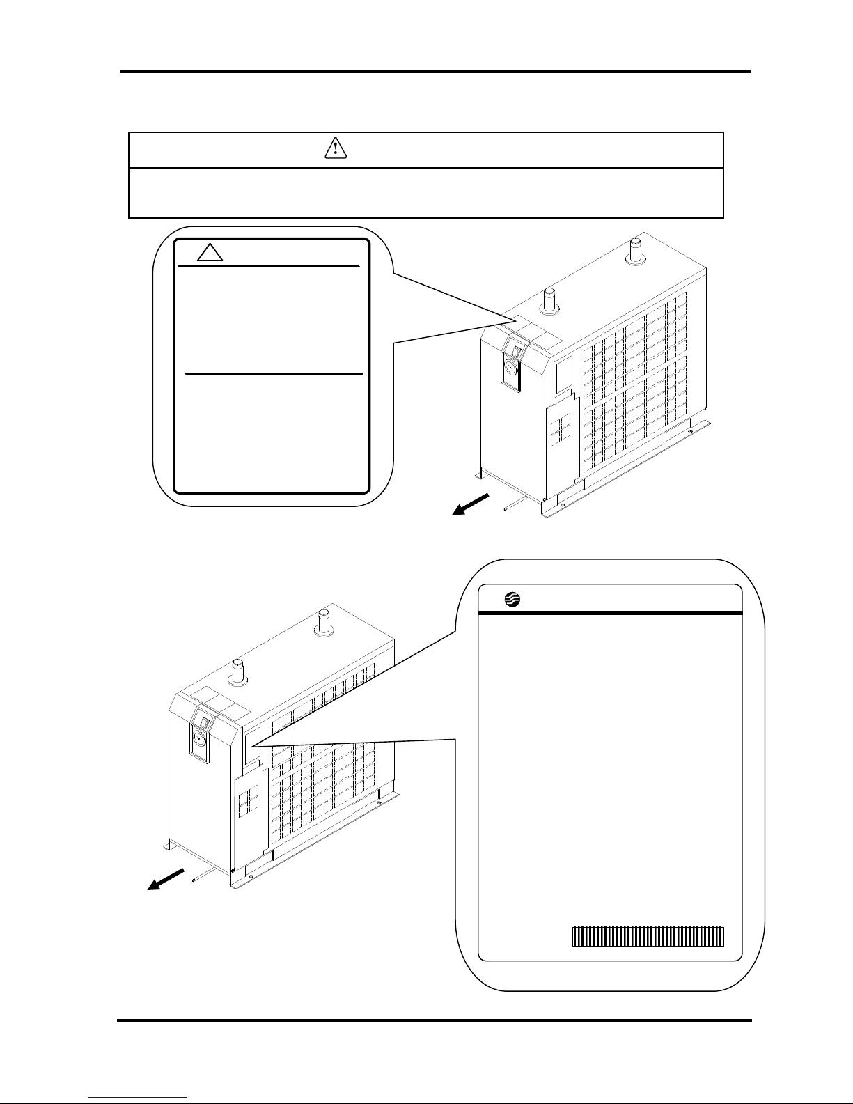
i-2-6 Positions of Danger Warning Label
Warning
・Read with caution and pay attention to the notations of danger warning labels.
・Do not remove or rub danger warning labels.
・Confirm the positions of danger warning labels.
Front
WARNING 警告
!
1 Remove panels fo r maintenance only.
2 Never insert an ything into product to en sure
safety.
3 Cut power p rior to maintenance to prevent
electric sho ck.
4 Settle product to room temp.before main tenance topr event burn or frostbite.
5 Ensure zero air pressure before replacing parts.
1 点検以 外はパネ ルを取り外さないこと 。
2 回転物 があるので 指、棒状の 物を差し
込 まないこと 。
3 感電の 恐れがあ るので、点 検の前には 電源を
切るこ と。
4 火傷の 恐れがあ るので、点 検の前には 装置を
常温 にすること。
5 部品交 換の前には必ず、空気圧力を" 0"に
するこ と。
!
IDFB Series
Air Dryer i Safety Instructions
i-2Danger Classifications & Position of Hazard warning Labels
i - 5
IDX-OM-K021
Front
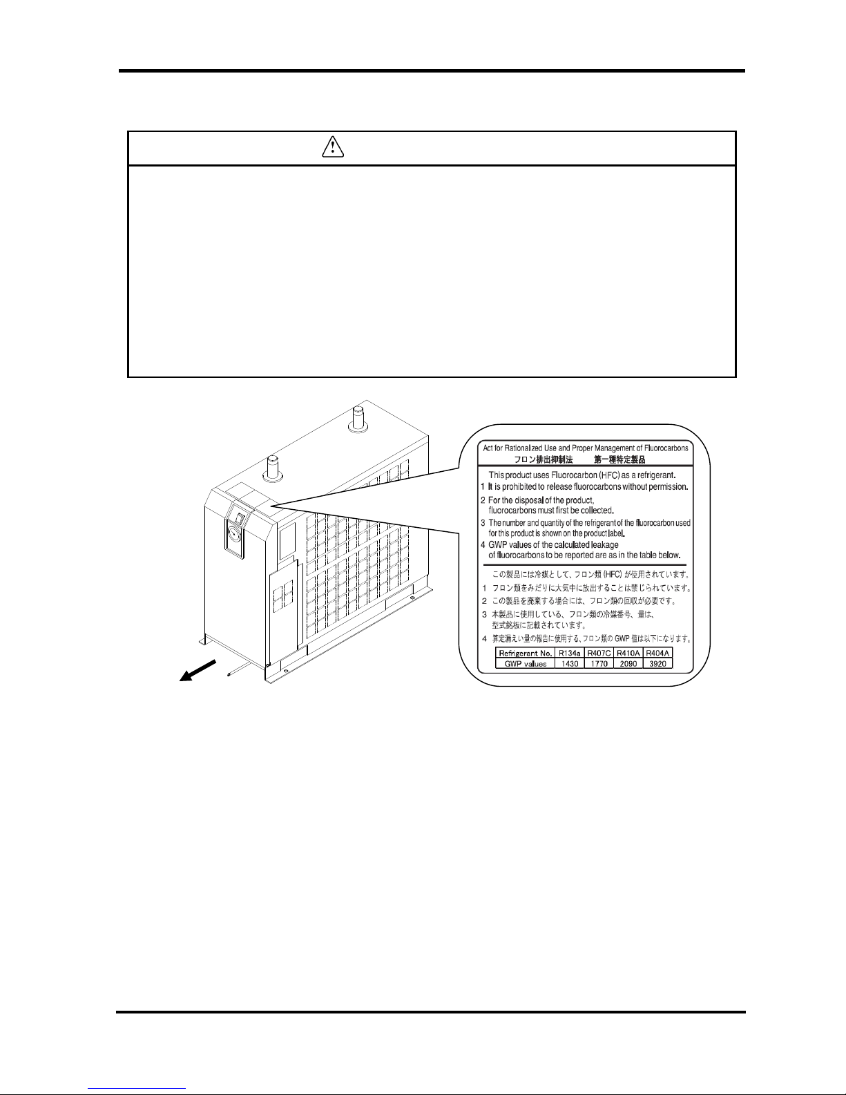
i-2-7 Hazard of Refrigerant
Caution
・This equipment uses Fluorocarbon (HFC) as a refrigerant.
・It is strictly forbidden to emit Fluorocarbon into the atmosphere. Before you repair the
refrigerant circuit, you should collect the refrigerant with proper evacuation system.
The collected refrigerant should be properly recycled by qualified agency. Only
personnel with proper credential are allowed to handle refrigerant.
・Only properly trained qualified personnel are allowed to remove the cover panel of the
equipment.
・The quantity and the type of Fluorocarbon are mentioned on the specification label.
See Page i - 6, i - 7.
IDFB Series
Air Dryer i Safety Instructions
i-2Danger Classifications & Position of Hazard warning Labels
i - 6
IDX-OM-K021
i-2-8 Cautions about Usage
Warning
Please follow the instructions on all warning labels. Do not remove or deface
warning labels, and confirm the location of warning labels.
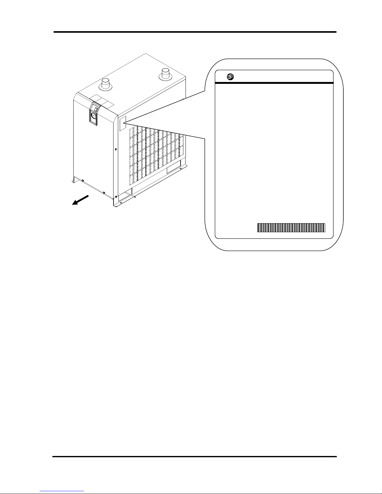
i-2-9 Other Label
IDFB22E / 37E
Front
Front
CAUTION 注意
!
1 Read manual before operation.
2 Ensure vantilation and maintenance
space.
3 Keep water away from the product.
4 Secure In / Out connector with spanner
during piping.
5 Wait 3 minutes before restart.
6 Ensure Running Condition / Evaporating
Temp. in green zone.
1 ご使用 前に必ず取 扱説明書を 読んでくださ い。
2 通風、 メンテナンススペース を確保して
ください。
3 雨や水滴がかからないよう にしてください 。
4 IN/ OUTポートをスパ ナで固定して
配管してくだ さい。
5 再起動 は運転停止 3分後に行 ってください 。
6 RU NNING CON DITIO N・蒸発 温度計は
グリーン帯で使用 してください 。
SMC AIR DRYER
MODEL
VOLTAGE
RATED CURRENT
MCA
MOPD
CMP LRA
AIR FLOW RATE
MAX. INLET PRESS.
MAX. INLET TEMP.
MAX.AMBIENT TEMP
MIN. AMBIENT TEMP
REFRIGERANT R134a
LO. SIDE PRESS.
HI. SIDE PRESS.
WEIGHT
SERIAL No.
MAKER
*12456789*
IDFB Series
Air Dryer i Safety Instructions
i-2Danger Classifications & Position of Hazard warning Labels
i - 7
IDX-OM-K021
IDFB55E / 75E
SMC AIR DRYER
MODEL
VOLTAGE
MCA
MOPD
COMPRESSOR RLA/LRA
FAN MOTOR HP/FLA
AIR FLOW RATE
MAX. INLET PRESS.
MAX. INLET TEMP.
MAX.AMBIENT TEMP.
MIN. AMBIENT TEMP.
REFRIGERANT R407C
LO. SIDE PRESS.
HI. SIDE PRESS.
WEIGHT
SERIAL No.
MAKER
*12456789*
Front
IDFB Series

Air Dryer i Safety Instructions
i-3Disposal
i - 8
IDX-OM-K021
IDFB Series
i-3 Disposal
When you dispose of the equipment, you should collect the refrigerant and the refrigerant oil inside the
refrigerant circuit.
Caution
This equipment contains Fluorocarbon HFC.
It is strictly forbidden to emit Fluorocarbon into the atmosphere. Before you
repair the refrigerant circuit, you should collect the refrigerant with proper
evacuation system. The collected refrigerant should be properly recycled by
qualified agency. Only personnel with proper credential are allowed to
handle refrigerant.
Only properly trained and qualified personnel are allowed to remove the
cover panel of the equipment.
The quantity and the type of Fluorocarbon are mentioned on the
specification label. See Page i - 6, i - 7.
Caution
Dispose of the refrigerant and refrigerant oil according to the regulation of
local government.
Only personnel with proper credential are allowed to collect refrigerant and
refrigerant oil.
Only properly trained and qualified personnel are allowed to remove the
cover panel of the equipment.
For any questions, please contact our factory or SMC authorized dealers.
Air Dryer i Safety Instructions
i-4 Limited warranty and Disclaimer / Compliance Requirements
i - 9
IDX-OM-K021
IDFB Series
i-4 Limited warranty and Disclaimer / Compliance Requirements
The product used subject to the following “Limited warranty and Disclaimer“ and “Compliance Requirements.
Read and accept them before using the product.
Limited warranty and Disclaimer
1. The warranty period of the product is 1 year in service or 1.5 years after the product is delivered.
Also, the product may have specified durability, running distance or replacement parts. Please consult
your nearest sales branch.
2. For any failure or damage reported within the warranty period which is clearly our responsibility, a
replacement product or necessary parts will be provided.
This limited warranty applies only to our product independently, and not to any other damage incurred
due to the failure of the product.
3. Prior to using SMC products, please read and understand the warranty terms and disclaimers noted in
the specified catalog for the particular products.
Compliance Requirements
1. The use of SMC products with production equipment for the manufacture of weapons of mass
destruction (WMD) or other weapon is strictly prohibited.
2. The exports of SMC products or technology from one country to another are govemed by the relevant
security laws and regulation of the countries involved in the transaction. Prior to the shipment of a SMC
product of a SMC product to another country, assure that all local rules goveming that export are known
and followed.
Caution
The Product is provided use in manufacturing industries.
The product herein described is basically provided for peaceful use in manufacturing industries.
If considering using the product in other industries, consult SMC beforehand and exchange
specifications or a contact if necessary. If anything is unclear, contact your nearest sales branch.
Air Dryer 1Parts Name and Functions
1-1Parts Name and Functions
1 - 1
IDX-OM-K021
IDFB Series
1 Parts Name and Functions
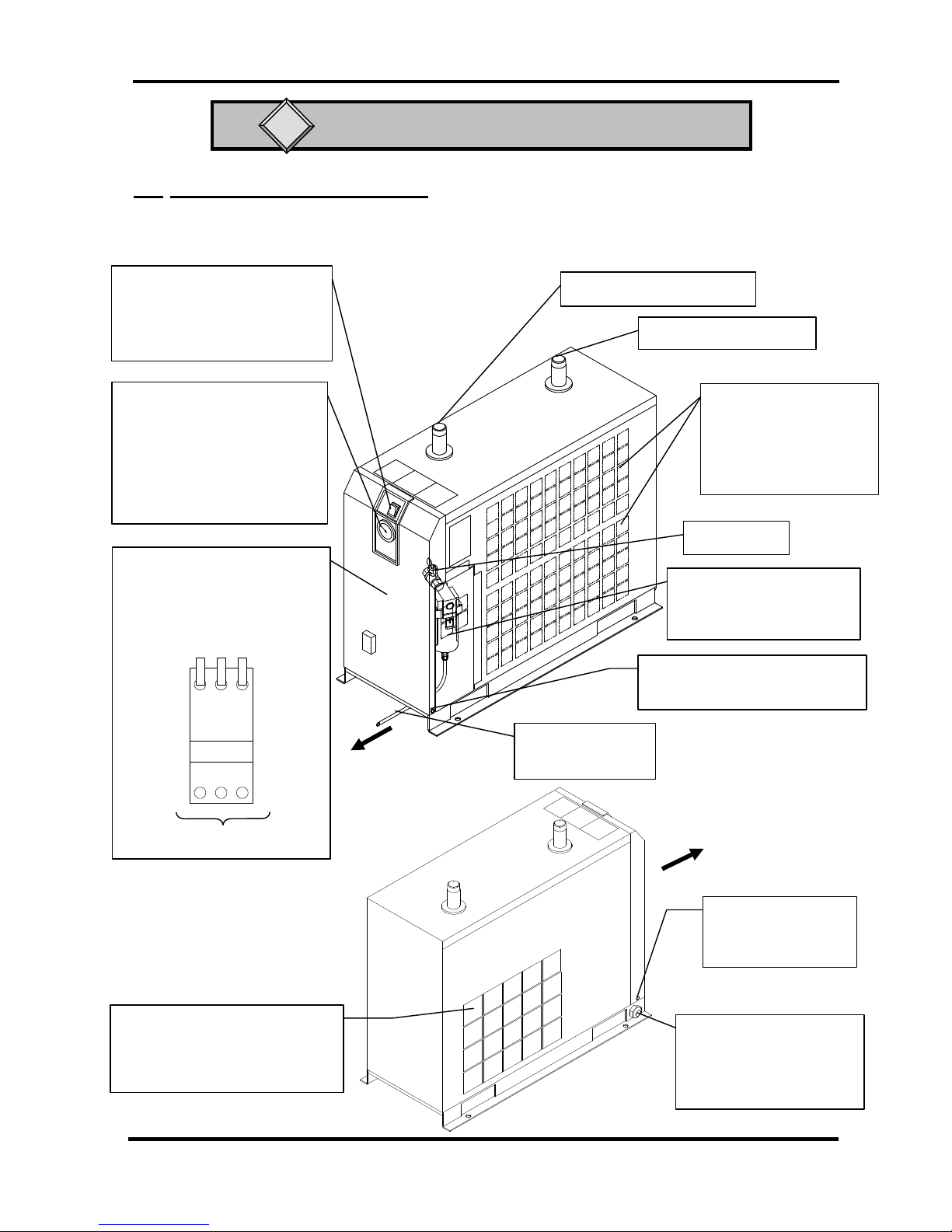
1-1 Parts Name and Functions
• IDFB22E, 37E
Front
Switch with Lamp
(ON /OFF Switch)
The lamp is continuously ON
during normal operation.
Evaporation Thermometer
Indicates the evaporating
temperature of refrigerant on
low-pressure side.
During normal operation, the
indicator remains in the
green zone.
Ventilation Grille
(Exhaust)
Hot air will be exhausted
by condenser fan. Do
not block these vents.
Panel Lock (x 2)
Another one is on opposite side.
Drain Tube
Discharges drain.
Auto Drain
Check if drained correctly
once a day.
Compressed Air (IN)
Compressed Air (OUT)
Ball Valve
Front Panel
You can see the terminal block
when you remove this cover.
Connect the power cable through
the rubber grommet.
Customer Connection Side
Front
Rubber Grommet
Power cord outlet
(IDFB22E-11*
:Power cable wirth Plug)
Panel Lock (x 2)
Another one is on
opposite side.
Ventilation Grille (Suction)
Ambient air will be sucked by
condenser fan. Do not block
these vents.
L N PE
Air Dryer 1Parts Name and Functions
1-1Parts Name and Functions
1 - 2
IDX-OM-K021
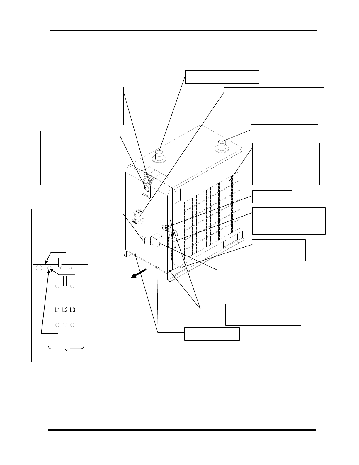
IDFB Series
• IDFB55E, 75E
Panel Lock (x 2)
Front
Switch with Lamp
(ON /OFF Switch)
The lamp is continuously ON
during normal operation.
Evaporation Thermometer
Indicates the evaporating
temperature of refrigerant on
low-pressure side.
During normal operation, the
indicator remains in the
green zone.
Ventilation Grille
(Exhaust)
Hot air will be exhausted
by condenser fan. Do
not block these vents.
Panel Lock (x 4)
There are on opposite too.
Drain Tube
Discharges drain.
Auto Drain
Check if drained correctly
once a day.
Compressed Air (IN)
Compressed Air (OUT)
Ball Valve
Front Panel
You can see the terminal block and
earth terminal block when you remove
this cover. Connect the power cable
through the rubber grommet.
Thermal Relay
(The thermal relay is placed at the
inside of a front panel.) Refer to page
5-3 to reset the thermal relay.
High Pressure Switch
(The high pressure switch is placed at
the inside of a front panel.) Refer to page
5-3 to reset the high pressure switch.
Earth Terminal Block
Screw = M4×10
Customer Connection Side
Customer Connection Point
(Earth Cable of customer)
Air Dryer 1Parts Name and Functions
1-1Parts Name and Functions
1 - 3
IDX-OM-K021
IDFB Series
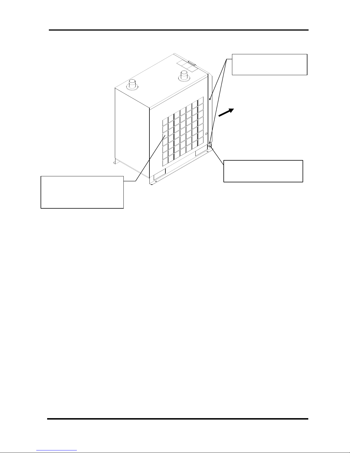
Front
Rubber Grommet
Power cord outlet
Panel Lock (x 4)
There are on opposite too.
Ventilation Grille (Suction)
Ambient air will be sucked by
condenser fan. Do not block
these vents.

Air Dryer
2 Transportation / Installation
2-1Transportation
2 - 1
IDX-OM-K021
2 Transportation / Installation
Warning
Only properly trained, qualified personnel are allowed to perform tasks such as:
Operation, installation, relocation of equipment and maintenance works.
Strongly recommend to prepare the spare dryer when applying the dryer for
important equipment or system.
2-1 Transportation
When you transport the equipment, you should follow the instructions below:
You should lift the equipment from the base surface with careful attention to prevent tipping over.
Do not lay the equipment sideways, or you will damage the equipment.
Do not suspend the equipment from the ceiling or hang from the wall.
Warning
This equipment is heavy.
Each model weights about 110lbs (50kg) or more. More than one person is required to move
it, a forklift is necessary.
IDFB Series

Air Dryer
2 Transportation / Installation
2-2Installation
2 - 2
IDX-OM-K021
2-2 Installation
2-2-1 Location
The equipment should not be used or stored in the following conditions: Those conditions will cause
not only malfunction but also failures.
Environment where the equipment is exposed
to rainwater, moisture, salt water or oil.
Locations where the equipment is exposed to
dust or particles
Locations where the equipment is exposed to
flammable, combustible or explosive fumes.
Locations where the equipment is exposed to
corrosive gas or solvent.
Locations where the equipment is exposed to
direct sunlight or radiated heat.
Locations where ambient temperature is
beyond following range:
On-stream: 36 to 104°F (2 to 40oC)
Storage: 32 to 122°F (0 to 50oC)
(when there is no drain water
inside of the piping)
Locations where temperature changes rapidly.
Locations where strong electromagnetic noise
is generated.
Circumstances where static electricity is
produced or discharged through the body of the
equipment
Locations where strong high frequency shock
wave is generated
Locations where danger of thunder is apparent.
Locations where loading on vehicles, marine
vessels, and so on
Locations where altitude is higher than 2,000
meters
Circumstances where strong vibration or
impact are transmitted.
Circumstances where too much force and
weight are put on the body of the equipment
that causes it to deform.
Circumstances where not enough clearance
spaces to do maintenance
Spaces needed for maintenance
Front : 2feet (0.6m)
Rear : 2feet (0.6m)
Top : 2feet (0.6m)
Right : 2feet (0.6m)
Left : 2feet (0.6m)
Locations where ventilation grille of the
equipment can be blocked.
Locations where the dryer could intake warm air
(for example from a compressor or other
dryers).
Condition which has sudden pressure/flow rate
changes.
IDFB Series

Air Dryer
2 Transportation / Installation
2-2Installation
2 - 3
IDX-OM-K021
2-2-2 Tie Down
The air dryer should be installed on a vibration-free, stable, horizontal, flat surface.
Refer to “Chapter6 6-3 Dimensions” for the dimensions.
This model should be installed using anchor bolts (not included) to prevent shifting during a potential
earthquake.
2-2-3 Air piping
Connection to the inlet and outlet of compressed air should be made removable by using union or similar
connection.
Support the IN/OUT ports with a wrench during tightening or loosing of fittings.
Do not allow the equipment to support the weight of the piping.
Isolate the vibration generated by the compressor.
If the temperature of compressed air on the inlet side is higher than 122°F (50
o
C), place an aftercooler
unit after the air compressor.
If the air supply makes high pressure fluctuation (pulsation), take any countermeasures such as
installing air tank.
Clean pipes and fittings before use and select a suitable filter to prevent dust, oil or chips from entering the
air dryer, which can cause failure to the equipment.
Use pipes and fittings that can withstand the operating pressure and temperature of the compressed air.
Make sure all connections are leak-free.
Provide bypass piping to make it possible to do maintenance without stopping the air compressor.
2-2-4 Drain Tube
A polyurethane tube (3/8inch) O.D. is attached to the auto drain. The end of the tube is open to
atmosphere to let drain flow through the tube into a collector or drain pipe.
The compressed air is used to push out the drain periodically. Fix the outlet end of the tube in order to
prevent whipping action during discharge.
Install the drain tube in such a way so that no drain is trapped.
During installation, make sure the dryer does not sit on the drain tube which is at the bottom of the unit. Be
careful to avoid the dryer from crushing the tube during installation.
We recommend the bypass piping sets
available separately as accessories.
Compressed Air (OUT)
Compressed Air (IN)
Valve (IN)
Valve (OUT)
Union Joint
Union Joint
Bypass valve
IDFB Series

Air Dryer
2 Transportation / Installation
2-2Installation
2 - 4
IDX-OM-K021
IDFB Series
Warning
・To handle drain discharge, follow the safety guidelines such as wearing protective
goggles, apron, and gloves.
・In cases where oil is mixed in the wastewater discharged from the auto drain, the liquid
would be considered as toxic waste and treatment is necessary in accordance with local
regulations.
2-2-5 Electric Wiring
Warning
Only properly trained and qualified personnel are allowed to perform wiring
work.
Before wiring, you must disconnect the power. Do not work under any
energized conditions.
Supply power from a stable source that is free from the effect of surge.
Referring to “6-1 Specifications,” make sure to install a GFCI breaker that has
the right short circuit capacity and load capacity.
Supply power of the equipment should meet the specifications on page 6-1.
The equipment must be grounded for safety.
Do not connect ground wire to a water pipe, a gas pipe, or a lightening rod.
Do not plug too many leads into a single socket.
The customer must prepare for countermeasures of the power failure.
The dryer may not start normally at the moment of power failure.
Circuit breaker must be properly selected to meet safety standard of local
regulations.
Always be sure to connect the protective conductor first, disconnect it last in
respect to the other connections.
Be sure that the protective conductor has some additional length in respect to
the live conductors, so that it is not subject to mechanical stresses.
Be sure to install the circuit breaker correctly so that it disconnects all live
conductors and so that the operating handle can be easily accessible.
How to connect wiring
・Take off the front panel in front of the product and connect the power supply (AC230V) to the
terminal base.
・Install a Ground Fault Circuit Interrupter(GFCI) to the power supply. (Prepare by yourself)
[sensitivity of leak current: 30mA and below, Rated current 10A (IDU75E…Rated current 20A) ]
Specification of power cable
Prepare following power cable.
Power cable: 16AWG (1.25mm2), Three-cores (including the ground cable) [IDFB22E/37E], Four-cores
(including the ground cable) [IDFB55E/75E], External diameter: about 0.3inch (8mm) to 0.5inch (12mm).
Additional length of about 4inch (0.1m) is needed to wire inside of the equipment.
Air Dryer
2 Transportation / Installation
2-2Installation
2 - 5
IDX-OM-K021
IDFB Series
Length of the power cable
The maximum length of the power cable should be no more than 98feet (30m).
Connecting to the power supply
Connect the power cable and the ground to the terminal block.
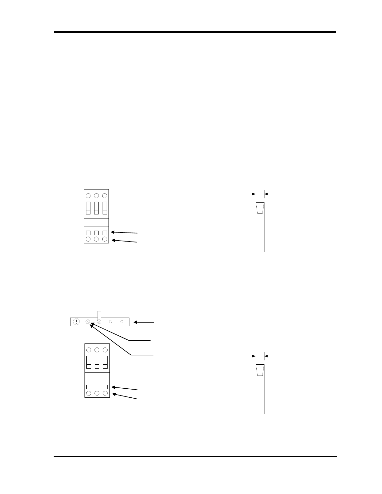
Wiring procedure
1. Remove the terminal block cover or the front panel.
2. Insert the cord through the rubber grommet and connect it to the terminal block (refer to the label on the
terminal block).
During wiring work, do not touch other sections except terminal block.
3. Insert the screwdriver into terminal block and open spring of terminal.
(The cable insulator must be stripped at 3/8inch (10mm).)
4. Insert the cable and remove the screwdriver.
5. Re-attach the cover or real panel after wiring is done.
IDFB22E, 37E
IDFB55E, 75E
L N PE
Cable entry
Screwdriver entry
Terminal block
118 to 138 mil
(3 to 3.5mm)
Applicable screwdriver
118 to 138 mil
(3 to 3.5mm)
Applicable screwdriver
L1 L2 L3
Earth terminal block
Screw = M4×10
Earth cable connection
Cable entry
Screwdriver entry
Terminal block

Air Dryer
2 Transportation / Installation
2-3Cautions for Reinstallation
2 - 6
IDX-OM-K021
IDFB Series
2-3 Cautions for Reinstallation
Caution
No one but someone who has enough knowledge about the product and incidental
devices should reinstall in another place. And following instructions must be executed.
If you move the product and reinstall it into another place after some operations (including trial running),
instructions that are not only following ones but also all of those in the chapter 2 should be followed.
Disassembly of the power cable
Cut off the power source when you disassemble the power cable.
Warning
No one but qualified personnel should do the electric wiring.
Cut off the power supply for safety before the wiring. Do not work under energized
condition.
Disassembly of the air piping
Warning
No one but qualified personnel should do the air piping.
Separate the compressor from the product for safety before removing the iping. Do not
remove any piping when there is remaining compressed air pressure inside of it.
・Remove the seal tape completely after detaching the piping. Remained tape will cause imperfect
cooling and failure by entering into the body of the product.
Residual compressed air pressure release procedure
Even while the dryer is removed, only when compressed air is needed, open the bypass piping valve.
Close the compressed air inlet and outlet valve.
Make sure the ball valve located next to the auto drain opened.
Open the auto drain residual pressure release valve to release air pressure inside the product. Refer to the
Figure at right.
Case Assembly
The ramainder depressure cock.
※It opens when turning in the
drection og the arrow of figure.

Air Dryer 3 Operation / Shutdown
3-1Check points before operation
3 - 1
IDX-OM-K021
3 Operation / Shutdown
Caution
Only properly trained and qualified personnel are allowed to perform operation/shutdown
of the equipment.
3-1 Check points before operation
Before trial run, check the following points:
Installed Conditions:
By visual inspection check that the equipment is level.
Make sure the equipment is tied down with anchor bolts.
Do not place heavy objects on the top of the equipment. Make sure piping does not add weight to
the equipment.
Power cord, and the ground should be connected firmly.
Drain tube should be connected correctly.
Make sure the piping for compressed air is connected correctly.
Make sure the ball valve located next to the auto drain opened.
3-2 Operation
Start operation according to the procedure below.
Turn on the breaker of the main power supply. Then, turn ON the ON/OFF switch.
The lamp will light up. Few minutes later, the cooling fan will rotate and hot air will be exhausted from
the ventilation grille.
Location of the ventilation grille: Right Side
Open the IN/Out side valve slowly. Make sure the bypass valve is completely closed. Confirm there
are no air leaks.
Depending on the condition of compressed air or ambient temperature, the cooling fan sometimes
alternates between start/stop at the beginning. Then, the refrigerant compressor will start and the
pointer of the evaporating temperature will indicate in the green zone. If the pointer indicates higher
than the green zone, refer to “Chapter 5 Troubleshooting.”
After running for a while, moisture will be discharging from the drain tube automatically.
Caution
・Avoid frequent On/Off operation, which may cause problems.
・The auto drain used for the equipment has a structure that closes the valve with air
pressure higher than 22psi(0.15MPa).
Therefore, until the pressure increase, air will be emitted form the drain outlet at the
begining of opening the IN side valve. Keep in mind that sometime the pressure cannot
increase enough with air compressor that has low dischage flow rate.
・Avoid using this product under the condition which has sudden pressure/flow rate
changes. Otherwise, drain (condensed water) may flow out to the secondary piping.
IDFB Series

Air Dryer 3 Operation / Shutdown
3-3Shutdown
3 - 2
IDX-OM-K021
3-3 Shutdown
① Turn off the ON/OFF switch.
② The lamp will go out and then, the operation will stop. Depending on the condition of operation, hot air
continues to be emitted from the ventilation grille by the cooling fan for a while after turning off the switch.
3-4 Cautions about restart
・Wait at least 3 minutes before restarting the air dryer after it has been shut down. Failure to do this may
cause safety devices to trip due to over load. If it is not possible to restart, refer to “Chapter 5
Troubleshooting.”
3-5 Check points before restart
Check following points before you start operation. If any abnormalities occur, immediately stop the operation.
Turn off the ON/OFF switch follow by the breaker of the main power supply.
There are no air leaks.
Air pressure, temperature, flow rate, and ambient temperature meet the specifications.
Moisture is being discharged from the drain tube.
The pointer of evaporating temperature indicates in the green zone.
Drainage should not be exhausted from the outlet of the air dryer.
There are no abnormal sound, vibration, or odor.
3-6 Precautions for long-term non-operation
If the product will not be operated for more than 24 hours, for example at the weekend, turn off the
ILS (Switch with lamp) or power supply, for energy saving and safety. It is also recommended to
release the pressure and residual drainage inside the compressed air piping and this air dryer.
The residual drainage in the air dryer may splash over the outlet when the operation is re-started, so
it is recommended to install a filter on the outlet of the air dryer.
IDFB Series

Air Dryer
4 Maintenance
4-1Daily Inspection
4 - 1
IDX-OM-K021
4 Maintenance
4-1 Daily Inspection
Check following points during normal operations. If you find some problems, immediately stop the dryer and
refer to “Chapter 5 Troubleshooting” as soon as possible.
There is no air leaks.
The running lamp is on during operation
Moisture is being discharged from drain tube
The pointer of the evaporating temperature indicates in the green zone
The pointer of the evaporating temperature indicates about 41 to 59°F (5 to15
o
C) lower than that of the
ambient temperature when compressed air stops supplying to the air dryer.
There is no abnormal odor or smoke coming from the equipment.
It is recommended to keep a maintenance/service record. Please refer to “Chapter 12-1 Service Record”
4-2 Periodical Maintenance
4-2-1 Cleaning of ventilation grille (suction grille)
Clean dust and other foreign particles from the ventilation area with vacuum cleaner or air blow nozzle once a month.
Caution
During air blowing, put on protective glass and mask to prevent dusts from coming into
throat or eyes.
4-2-2 Service parts
It is recommended to replace the following parts regularly. The interval shown in this operation manual
depend on the operating conditions (ambient temperature, installation environment, etc.), so that they
are for reference .
Table 1. List of parts to be replaced regularly
*Note)If it is mounted by option ”T” (With terminal block for power supply , run , alarm signal and remote
operation) or special order.
4-2-3 Cleaning of the case assembly
Remove the dust deposited in the auto drain case assembly every month. Use neutral detergent for cleaning. If the
degree of dirt is heavy and operating failure still continues even after cleaning, replace the product. Also, shorten
cleaning interval from the next time.
Part No. of case assembly
Parts No.
Description
IDFB22E
IDFB37E
IDFB55E
IDFB75E
AD48N-Z (Thread Symbol : N)
Auto Drain
1 1 1
1
AD48 (Thread Symbol : None)
Auto Drain
1 1 1
1
Description
Recommended replacement interval
Pressure switch
One Million times.
Fan motor
20,000 hours
Magnetic Contactor, Magnetic Switch (Note)
One Million times.
IDFB Series

Air Dryer
4 Maintenance
4-2Periodical Maintenance
4 - 2
IDX-OM-K021
・ Maintenance of the air dryer should only be carried out by someone with sufficient knowledge and
experience of air dryers and related equipment.
・ Before carrying out maintenance, the important warnings in this manual must be thoroughly read and
understood.
・ When replacing or cleaning parts of the air dryer, be sure to remove the compressed air pressure inside
the air dryer to “0”. Never remove the case assembly when the air dryer is operated or air pressure
remains inside. It is extremely dangerous if compressed air pressure remains inside the air dryer, as
parts may come flying off at speed when loosened, or other unexpected accidents.
・ This product has parts that become hot during operation and a power supply with high voltage applied.
There is a risk of burns due to heat or electrification by high voltage. Even when operation is shut down
after switching off the air dryer’s illuminated light, there are also charging lines. When working on the
charged sections, be sure to switch off the earth leakage breaker installed before starting work.
・ As some parts of the air dryer will remain hot, there is a risk of burns due to residual heat after the
power is switched off. So do not carry out replacement work until the temperature of these parts has
fallen to 50℃ or less. Wait for about 10 to 15 minutes as a guide.
・ When carrying out maintenance work on the auto drain strainer and auto drain, there is a risk of
touching the drain fluid during work. Please follow the safety procedure for operators specified by
customer.(Example: carry out work wearing safety glasses, apron and gloves to prevent discharged
fluid from touching the human body.)
・ Use neutral detergent solution to clean parts such as the auto drain strainer and auto drain. Never
use solvent such as thinner.
・ When removing the outer casing panel or case assembly of the auto drain, wear gloves to prevent
injuries.
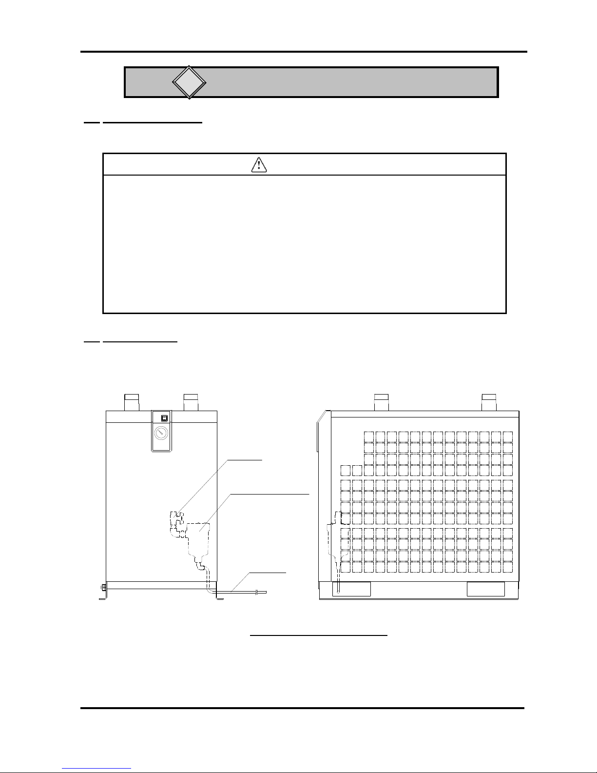
How to clean and replace the case assembly.
When carrying out maintenance work on the auto drain and auto drain strainer, please
follow the steps below.
・Turn off the illuminated ON/OFF switch.
・ Disconnect the earth leakage breaker at the power supply or unplug the power plug from the socket.
・ Fully close the IN/OUT valves. Only open the bypass when compressed air is required during work.
・Only the point that is necessary for work please remove a decoration panel.
Warning
Danger
IDFB Series

Air Dryer
4 Maintenance
4-2Periodical Maintenance
4 - 3
IDX-OM-K021
・ Close the ball valve.
・ Open the bleed valve by turning it anticlockwise to release
air left in the product.
・ Remove the drain tube from the case assembly.
・ Hold the case assembly lightly and pull down the lock button with
thumb. Then, turn the case assembly to the left (or right) to 45°to
align the marks,
Release your thumb from the lock button and slowly pull down the
case assembly (vertically) to remove it.
・ Pour solution of neutral detergent into the case assembly and
shake it well to clean.
・ Check the case O-ring for damage such as scratches, twisting
or foreign particles attached to it. Then, apply grease thinly
and fit it in the groove in the case assembly.
・ Fit the case assembly to the auto drain body. Turn it untill the lock
button clicks.
・ Try to turn the case assembly lightly and check that it does not
turn. If it turns, start with fitting the case assembly to the body
again.
・ Try to turn the case assembly lightly and check that it does not
turn. If it turns, start with fitting the case assembly to the body
again.
・ Close the bleed valve by turning it clockwise and fit the
drain tube as it was.
・ Open the ball valve.
・ If the case assembly is damaged or very dirty, replace it
with a new one.
S
O
Drain tube
release bush
Lock button
Drrain tube
Ball valve
Bleed valve
Ball valve
Float assembly
Turn to 45°
(right or left)
Auto drain strainer
Bleed valve
Pull down the case
assembly slowly
IDFB Series

Air Dryer 5 Troubleshooting
5-1Cause and countermeasure of errors
5 - 1
IDX-OM-K021
IDFB Series
5 Troubleshooting
5-1 Cause and countermeasure of errors
Should any problem occur, inspect the following table, and if the problem cannot be solved, shut off the power
supply and then contact one of our sales offices for further instructions.
Problem
Probable Causes
Remedy
Although the
switch with lamp
is turned on, the
lamp does not
light up and the
product does not
start operating.
The power supply cable has been
loosened or disconnected.
-Perform proper connection on the power cord and
plug.
The ground fault circuit
interrupter is not turned on.
Check the capacity of the ground fault circuit
interrupter.
- Check the product was not restarted within 3 minutes
after being stopped.
- Turn on the ground fault circuit interrupter and try to
operate.
If the ground fault circuit interrupter turns back off,
the insulation failure of the product is suspected. Turn
off the power supply and contact SMC.
Power line connection is wrong.
(Phase Reversal Relay switch
can’t be ON.)
-Connect the power line correctly.
Running lamp
extinguishes and
compressor stops
during operation
but
resumes normal
operation
Switch with lamp
after a
period of time.
The product is installed in an
inappropriate location.
Ambient temperature is excessive.
- Improve ventilation condition and reduce the ambient
temperature as much as possible.
-Reset the protective circuit by referring to “5-2 How
to reset the thermal relay and high pressure
switch.” (Only IDFB55E,75E)
The ventilation port is obstructed by a
wall or clogged with dust.
- Keep the product 600mm or more away from the
surrounding walls.
- Clean the ventilation ports once every month.
-Reset the protective circuit by referring to “5-2 How
to reset the thermal relay and high pressure switch.”
(Only IDFB55E,75E)
The compressed air temperature is
too high.
- Improve the ventilation in the location where the air
compressor is installed, or decrease the ambient
temperature to allow the discharge air temperature of
the air compressor to go down.
- Install an aftercooler after the air compressor to reduce
the temperature.
-Reset the protective circuit by referring to “5-2 How
to reset the thermal relay and high pressure
switch.” (Only IDFB55E,75E)
The fluctuation of the power supply
voltage is too large.
- Install a power supply transformer or use a different
power supply to provide appropriate voltage.
- The fluctuation of the power supply voltage should be
kept within +/-10% of the rated voltage.
-Reset the protective circuit by referring to “5-2 How
to reset the thermal relay and high pressure
switch.” (Only IDFB55E,75E)
Air Dryer 5 Troubleshooting
5-1Cause and countermeasure of errors
5 - 2
IDX-OM-K021
IDFB Series
Problem
Probable Causes
Remedy
The evaporation
thermometer is
over the green
area without hot
air coming from
the ventilation
port (exhaust
port).
(The compressor
for refrigeration
has stopped with
the lamp lit up.
The product is installed in an
inappropriate location.
Ambient temperature is excessive.
- Improve ventilation condition and reduce the ambient
temperature as much as possible.
The ventilation port is obstructed by a
wall or clogged with dust.
- Keep the product 600mm or more away from the
surrounding walls.
- Clean the ventilation ports once every month.
The compressed air temperature is
excessive.
- Improve the ventilation in the location where the air
compressor is installed, or decrease the ambient
temperature to allow the discharge air temperature of
the air compressor to go down.
- Install an aftercooler after the air compressor to reduce
the temperature.
The fluctuation of the power supply
voltage is too large.
- Install a power supply transformer or use a different
power supply to provide appropriate voltage.
- The fluctuation of the power supply voltage should be
kept within +/-10% of the rated voltage.
The built-in overload relay of the
compressor for refrigeration has
started.
- Check the product was not restarted within 3 minutes
after being stopped.
The evaporation
thermometer is
over the green
area with hot air
coming from the
ventilation port
(exhaust port).
The product is installed in an
inappropriate location.
Ambient temperature is excessive.
- Improve ventilation condition and reduce the ambient
temperature as much as possible.
The ventilation port is obstructed by a
wall or clogged with dust.
- Keep the product 600mm or more away from the
surrounding walls.
- Cl ean the ventilation ports once every month.
The compressed air temperature is
excessive.
- Improve the ventilation in the location where the air
compressor is installed, or decrease the ambient
temperature to allow the discharge air temperature of
the air compressor to go down.
- Install an aftercooler after the air compressor to reduce
the temperature.
Moisture is
generated at the
downstream of
the compressed air
line.
The bypass valve is open.
- Be sure to fully close the bypass valve.
Condensate is not drained from the
auto drain.
- Check the draining piping is not used in an upward
direction nor bent.
- Check the auto drain.
- Check the auto drain strainer.
The pressure fluctuation (pulsation)
of the compressed air is too high.
-Install an air tank on the primary side of the dryer.
-Avoid intermittent compressed air flow.
Residual drainage in the air dryer
splashes over when the unit is
re-started.
-Install a filter on the outlet of the air dryer.
- Blow the unit by air to eliminate the residual drainage
after stopping or re-starting the operation.
The piping of a different system
without an air dryer joins the piping
after the product.
- Install another air dryer (this product) in that system.
- Keep the two systems separate.
The compressed
air pressure is
too large.
The valves at the inlet and outlet of
the piping of the product are not fully
opened.
- Be sure to fully open the valves at the inlet and outlet of
the product.
The air filter, etc. installed in the
compressed air piping has got
clogged.
- Replace the element of the air filter.
(Follow the Operation Manual of the equipment.)

Air Dryer 5 Troubleshooting
5-2How to reset the thermal relay and high pressure switch (Only IDFB55E, 75E)
5 - 3
IDX-OM-K021
IDFB Series
++
+
+
5-2 How to reset the thermal relay and high pressure switch (Only IDFB55E, 75E)
If light goes off during operation and refrigerating compressor stops, the thermal relay or high pressure switch
(for only the IDFB55E and IDFB75E) to protect the refrigerating compressor starts operating and needs to be
reset manually. For the position of the thermal relay and high pressure switch, refer to page 1-2.
Before resetting the thermal relay and high pressure switch identify and cure problem that caused the unit to trip
out, by referring to “5-1 Cause and countermeasure for errors”.
Danger
Be sure to turn off the ON/OFF switch.
How to reset a thermal relay
①Turn off the ON/OFF switch.
②Take off the front panel. You can see the electric parts bracket.
The thermal relay can be found left side and upper side in the electric parts bracket.
③Confirm that a green indication does not appear in the
indication window of thermal relay.
If the green indication appears, there are other possible causes
and contact an SMC Authorized Dealer keeping the power supply on.
④Press the blue reset button and confirm that the green indication
comes to appear at the indication window.
⑤Put back the front panel.
⑥When the ON/OFF switch is turned on, the product will restart
operation.
How to reset a high pressure switch
①Turn off the ON/OFF switch.
②Take off the front panel. You can see the electric parts bracket.
The high pressure switch can be found at right side of electric parts bracket.
③Press the red reset button.
④Put back the front panel.
⑤When the ON/OFF switch is turned on, the product will
restart operation.
Thermal relay
High pressure switch
High pressure
switch bracket
Reset button
(Red)
Indication
window
Reset
button (Blue)
Electric parts bracket
Thermal relay
High pressure switch

Air Dryer 6 References
6-1Specifications
6 - 1
IDX-OM-K021
6 References
6-1 Specifications
Model
Specification
IDFB22E-11□ IDFB22E-23□ IDFB37E-23□ IDFB55E-46□ IDFB75E-46□
Air FlowRate
(ANR)(Note 1)
At Expected Outlet
Press.Dew Point of 37°F(2.8℃)
107SCFM
(182 m
3
/h)
161SCFM
(273 m3/h)
226SCFM
(384 m3/h)
300SCFM
(510 m3/h)
At Expected Outlet
Press.Dew Point of 45°F (7.2℃)
120SCFM
(205 m
3
/h)
173SCFM
(294 m3/h)
258SCFM
(438 m3/h)
353SCFM
(600 m3/h)
At Expected Outlet
Press.Dew Point of 50°F (10℃)
130SCFM
(221 m
3
/h)
181SCFM
(308 m3/h)
297SCFM
(504 m3/h)
406SCFM
(690 m3/h)
Rated
Condition
Operating Pressure
100psig (0.7MPa)
Inlet Air Tem perature
100°F (37.8℃)
Ambient Temperature
100°F (37.8℃)
Voltage
115V 60Hz 230V 60Hz 460V 60Hz
Operating
Range
Working Fluid Compressed Air
Inlet Air Tem perature
40-122°F (5-50℃)
MIN.Inlet Air Pressure
22psig (0.15MPa)
MAX.Inlet Air Pressure
150psig (1.0MPa)
Ambient Temperature
36-104°F (2〜40℃) Relative Humidity of 85% or less
Electrical
Specification
Power Source
1φ AC115V±
10% 60Hz
(Note4)
1φ AC230V±10% 60 Hz ( Note4) 3φ AC460V±10% 60Hz (Note4)
Starting Current and LRA (Note2) 42A 26A 30A 27A
Operating Current (Note2) 9A 4.5A 5.6A 3.8A
Power Consumption (Note2) 1000W 1270W 2400W
Circuit Breaker Capacity (Note3) 15A 10A
Condenser forced air cooling
Refrigerant R134a(HFC) R407C(HFC)
Refrigerant Charge Quantity
18.7±0.4oz
(530±10g)
25.7±0.4oz
(730±10g)
15.2±0.4oz
(430±10g)
20.8±0.4oz
(590±10g)
Thread Type
and Size
Thread Symbol “N”
(male)
NPT1 NPT1-1/2 NPT2
Thread Symbol “None”
(male)
R1 R1-1/2 R2
Drain Tube
Thread Symbol “N” 3/8inch
Thread Symbol “None”
10mm
Painting Finish baking finish
Colour Panel : Urbanwhite1
Weight
119lbs
(54kg)
137lbs
(62kg)
258lbs
(117kg)
271lbs
(123kg)
Note1: The data for SCFM (ANR) is referring to the conditions of 68°F (20°C), 1atm . pressure & relative
humidity of 65%.
Note 2: The value is that of under specified condition.
Note 3: Install GFCI breaker with sensivity of
30mA.
Note 4: When short period power shortage (including instantly recovered shortage) is recovered, it may take
a longer starting period than usual starting or may not start due to the protective devices.
IDFB Series

Air Dryer 6 References
6-2Refrigerant with GWP reference
6 - 2
IDX-OM-K021
6-2 Refrigerant with GWP reference
Note:
1. This product is hermetically sealed and contains fluorinated greenhouse gases.
2. See specification table for refrigerant used in the product.
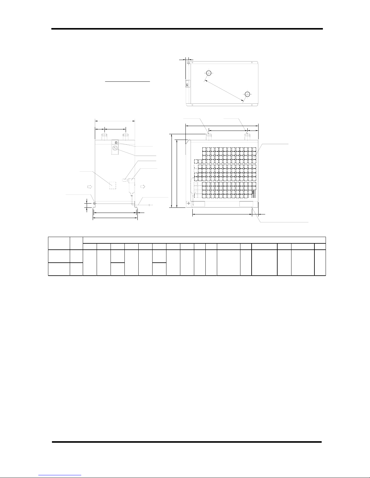
6-3 Dimensions
・IDFB22E / 37E
[4xDIA.13]
4xDIA.0.5
AIR OUTLET AIR INLET
9~11])OPPOSITION
φ
0.4[
φ
(WIRE
ELECTRICAL ENTRY
VENTILATION VENTILATION
DRAIN TUBE
BALL VALVE
LENGTH:35.4[900])
(O.D.3/8
WITH LAMP
SWITCH
THERMOMETER
EVAPORATION
BLOCK
TERMINAL
F
C
J
N M
E D
B
H
AUTO DRAIN
L
P
K
A
G
PORT SIZE
PORT SIZE
UNIT : inch [mm]
ABCDEFGHJK L M N P
30.5
[775]
33.7
[855]
13.4
[340]
26.8
[680]
IDFB37E 1/2
Model
Port
Size
Dimensions (inch [mm] )
IDFB22E 1
11.4
[290]
24.5
[623]
5.3
[134]
15.9
[405]
27.5
[698]
1
[25]
3.7
[93]
1.8
[46]
23.6
[600]
3.3
[85]
12.4
[314]
0.5
[13]
IDFB Series
Air Dryer 6 References
6-3Dimensions
6 - 3
IDX-OM-K021
・IDFB55E / 75E
N M
KL
P
C
F
DE
B
G H
Q
J
R
A
[DIA.9~11])
(WIRE DIA.0.4
ENTRY HOLE
POWER CORD
BLOCK
TERMINAL
(SIZE OF RECOMMENDED BOLT:M10)
AUTO DRAIN
DRAIN TUBE
BALL VALVE
LENGTH:39.4[1000]
VENTILATION
VENTILATION
THERMOMETER
EVAPORATION
WITH LAMP
SWITCH
DRAFT AIR OUTLET
AIR INLETAIR OUTLET
[4XDIA.13]
4XDIA.0.5
PORT SIZE PORT SIZE
UNIT : inch [mm]
ABCDEFGHJK L M N P
Q
R
Model
Port
Size
Dimensions (inch [mm] )
IDFB55E 2
1.4
[36]
IDFB75E 2
18.5
[470]
5.0
[128]
17.9
[455]
4.3
[110]
9.8
[250]2[50]
0.5
[13]
20.4±0.2
[519±5]
33.7
[855]
31.5
[800]
35.4
[900]
34.2
[868]
38.1
[968]
27.6±0.04
[700±1]
19.7±0.1
[500±2]
3.0
[75]
20.7
[526]
IDFB Series

Air Dryer 6 References
6-4Electrical Circuit
6 - 4
IDX-OM-K021
6-4 Electrical Circuit
GFCI
For Option R
N※2PE
L
※1
TB1
C1
MC
※2※1
OLR
Power Cable
with Plug
CM
Terminal Block
for Option S
CN
MC
CN
P
PRS
For Option V
※1
ILS
※2
For Option R
OLR
CN
PRS
P
ILS
TB1
MC
L
NPE
GFCI
For Option V
CN
C1
MC
CM
PE
PE
PRR
W
1
W
2
T
H
R
PRS1
MC1
P
MC2
P
EDV
PE
P
R
S
2
PRR
C01
THR
MC1
MC2
FM
CM
T
TB
記号 名称
CM Refrigerating Compressor
FM Fan Motor
FM1~6 Fan Motor
OLR Overload Relay
C1 Capacitor For Compressor Motor
C01 Capacitor For CM
ILS Switch with Lamp
PRS Pressure Switch
PRS1 Pressure Switch
PRS2 High Pressure Switch
TB Terminal Block
TB1 Terminal Block
TB2 Terminal Block
MC Magnetic Contactor
MC1 Magnetic Contactor
MC2 Magnetic Contactor
T Transformer
THR Thermal Relay
PRR Phase Reversal Relay
GFCI Ground Fault Circuit Interrupter
EDV Electronic Drain Valve
PC Power Cable
・
IDFB22E/37E-23
・
IDFB22E -11
IDFB Series
ForIDFB37
E
・
IDFB55E/75E-46

Air Dryer 6 References
6-5Compressed Air and Refrigerant Circuit/Operation Principles
6 - 5
IDX-OM-K021
6-5 Compressed Air and Refrigerant Circuit/Operation Principles
IDFB22E / 37E / 55E / 75E
Compressed Air Circuit
Humid hot air entering air dryer is cooled in the cooler. At this time , the condensate is separated from the air by the
drain separator and automatically discharged. The dry air is heated by the re-heater until it gets about the same
temperature as that of ambient air. It is then discharged from air dryer outlet.
Refrigerant Circuit
The Fluorocarbon charged in the refrigerant circuit is compressed by the compressor and cooled by the condenser
to become liquid. Then, going through the capillary tube, the refrigerant pressure and temperature (evaporating
temperature) decreased rapidly. Passing through the cooler part, it draws heat from the hot compressed air and
intensely boils. Finally, it is sucked into the compressor again. The hot gas bypass valve opens to prevent
compressor from freezing when compressed air is too cold.
IDFB Series

IDX-OM-K021
Air Dryer 7 Specification for Option A
7-1 Safety instructions
7- 1
IDFB Series
7
Specification for Option A
7-1 Safety instructions
When handling the product, take care to the following precautions.
Warning
Shut off the power supply when removing the panel for maintenance work, etc. The product
has a fan(s) and could cause serious danger to operators.
7-2 Specifications
Cool outlet air (50oF(10oC)) can be supplied. The air flow with this option is smaller than that of the
standard dryer.
7-3 Air piping
Since cool air comes out from an outlet of air dryers, carefully attach thermal insulation to the piping at air
outlet and keep the piping length as short as possible in order to prevent condensation on the outlet piping
and temperature increase on the outlet due to ambient temperature.
7-4 Air flow capacity
Note1) The data for ANR is referring to the conditions of 68F(20℃), 1atm. pressure & relative
humidity of 65%.
Note2) The conditions are the same as the ones for standard models other than air flow capacity.
Model
IDFB22E
IDFB37E
IDFB55E
IDFB75E
Air flow capacity (ANR)
Note1)
60Hz
47SCFM
(80m³/h)
80SCFM
(136m³/h)
103SCFM
(176m³/h)
150SCFM
(205m³/h)
Outlet air temp.
50°F(10℃)

IDX-OM-K021
Air Dryer 7 Specification for Option A
7-5 Compressed Air and Refrigerant Circuit / Operation Principles
7- 2
IDFB Series
7-5 Compressed Air and Refrigerant Circuit / Operation Principles
Capillary Tube
Condenser
Cooler
Drain Outlet
Compressed Air Inlet
Auto Drain
Thermoreter
Accmulator
Compressor
Fan Motor
Ball Valve
High Pressure Switch
Capacity Control Valve
Compressed Air Outlet
Pressure Switch
Compressed Air Circuit
The heat of humid hot air entering to the air drier enters to the cooler and is cooled and
dehumidified by cold fleon, separating the moisture.
The cold air is released from the air dryer.
Refrigerant Circuit
The Fluorocarbon charged in the refrigerant circuit is compressed by the compressor and
cooled by the condenser to become liquid. Then, going through the capillary tube, it is
decreased the pressure to reach a low temperature. Passing through the cooler part, it
draws heat from compressed air and intensely boils. Finally it is inhaled into the
compressor again. The capacity control valve opens to prevent dew drops from freezing
when compressed air is cooled enough.
Except IDFB75E

Air Dryer
8 Specification for Option K
8-1Safety instructions
8 - 1
This product mounts the auto drain in Item 2 Specifications. When performing the installation and
maintenance of the product, the following points must be understood and followed. Additionally, for
replacement work, read 4-2 “Periodical Maintenance” of the Operation Manual of standard product and
keep safety.
8-1 Safety instructions
When handling the product, take care to the following precautions.
8-2 Specifications
The auto drain has a maximum operating pressure of 1.6MPa and uses the metal case with a fluid
level indicator.
Warning
1. Do not remove the auto drain if air pressure remains of the product. When removing the
auto drain, stop the supply of air to the primary side of the product, exhaust the air from the
secondary side and ensure there is no residual pressure. If the air pressure is left at the
inside of the product, parts could suddenly pop out and cause accident when loosened.
2. Put gloves to prevent injury when removing the auto drain.
3. Operator could touch the drain waste from repalced auto drain. Follow the procedures
prepared by the customer to keep safety of operators. (Ex. Put protective goggles, apron
and/or gloves to protect body from toucing the drain waste for replacement worken
replacing the product.)
Model
Item
Thread Symbol “N”
Thread Symbol “None”
Auto drain
AD48-8Z-X2110
AD48-8-X2110
Max. operating pressure
240psig (1.6MPa)
Auto drain type
Float type
Auto drain valve type
N. O. (Normal Open: Open under non-energized status. )
Operating pressure
15 to 240psig (0.1 to 1.6MPa)
Operating fluid
Compressed air
IDFB22E, 37E
KQ2H11-02S(Thread Symbol “N”)
3/8(Thread Symbol “N”)
AD48-8-X2110(Thread Symbol “None”)
KQ2H10-02S(Thread Symbol “None”)
AD48-8Z-X2110(Thread Symbol “N”)
φ10(Thread Symbol “None”)
Level gauge
Drain Port
IDX-OM-K021
IDFB Series
8 Specification for Option K
Air Dryer
9 Specification for Option L
9-1Safety instructions
9 - 1
IDX-OM-K021
9 Specification for Option L
9-1 Safety instructions
When handling the product, take care of the following precautions.
9-2 Specifications
The specification of this product is dryer with heavy duty auto drain.
And, the auto drain has a maximum operating pressure of 240psig (1.6MPa).
Heavy duty auto drain assembly
Warning
1. Do not remove the auto drain if air pressure remains in the product. When removing the
auto drain, stop the supply of air to the primary side of the product, exhaust the air from the
secondary side and ensure there is no residual pressure. If the air pressure is left inside of
the product, parts could suddenly pop out and cause accident when loosened.
2. Put gloves to prevent injury when removing the auto drain.
3. Operator could touch the drain waste from repalced auto drain. Follow the procedures
prepared by the customer to ensure the safety of the operators. (Ex. Put protective goggles,
apron and/or gloves to protect body from toucing the drain waste when performing
maintance on the product.)
Drain tube
Heavy duty auto drain
Ball valve
IDFB Series

Air Dryer
9 Specification for Option L
9-3Specification of heavy duty auto drain (ADH4000-04)
9 - 2
IDX-OM-K021
9-3 Specification of heavy duty auto drain (ADH4000-04)
Note) Use for air compressor with flow more than 1.77SCFM (ANR) [3 m3/h (ANR)].
9-4 Maintenance
1. Check drain condition periodically (more than once a day).
Then push flushing button to open exhaust valve.
2. Pilot air is exhaust from the port indicated in the figure. Do not cover this exhaust port.
Clean exhaust port so that port is not blocked by dust, etc.
3. Close the ball valve before removing the heavy duty auto drain and open the bleed valve or push
the flushing button and confirm air pressure is released.
Model
IDFB55E/75E-46□-L
Order number (service parts)
ADH-E400
Auto drain type
Floating type
Auto drain valve type
N.O(normally opened: Open in the case of pressure loss)
Max. operating pressure
240psig (1.6MPa)
Working pressure range
7.5 to 240psig (0.05 to 1.6MPa)
Working fluid
Compressed air
Max. drain discharge
0.014SCFM(Pressure 0.7MPa,the case of water)
IDFB Series
Flush button
Body
Bleed valve
Pilot exhaust port
open
close

Air Dryer
10 Specification for Option R
10-1Safety instructions
10 - 1
IDX-OM-K021
10 Specification for Option R
This product mounts the Ground Fault Circuit Interrupter (GFCI) in Item 2. It will shut off the power
supply in case the product should have over current or current leakage. Additionally, the power
supply should be connected directly to the primary side of the GFCI. For the details of the GFCI such
as the specifications and mounting position, refer to Item 2 or later.
10-1 Safety instructions
When handling the product, take care to the following precautions.
10-2 Specifications of the GFCI
Dryer model number
Specifications of GFCI
IDFB22E-11□-R
Rated current: 15A, Current sensitivity: 30mA
IDFB22E/37E-23□-R
IDFB55E/75E-46□-R
Rated current: 10A, Current sensitivity: 30mA
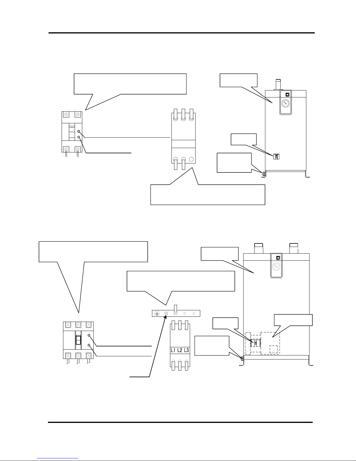
10-3 How to connect the power supply
1) Take off the front panel.
2) Take off the GFCI cover. (Only IDFB55E, 75E)
3) Insert the power cable prepared by the customer into the power code fixture and bring the
power cable near the terminal base through the base hole.
4) Connect the power cable to the terminal of the GFCI.
5) Put back the GFCI cover. (Only IDFB55E, 75E)
6) Put back the front panel.
Only qualified person must perform wiring and obserbing the following points.
1. Be sure to shut off the power supply before wiring. For safety, do not perform any work on the unit
with the power supply on. The power supply cannot be completely shut off just by turning off the
illuminated switch. Be sure to turn off all power lines connected to the product.
2. Supply the power from a stable source, free from surges.
3. Provide the power suitable for the product specifications.
4. Be sure to ground the product for the safety. Without grounding, the GFCI can not operate normally.
5. Do not ground to water pipe, gas tube or lightening rod line.
6. Do not connect too many wires to the same outlet, which could results in heat generation and fire.
7. Do not retrofit the wiring of the dryer and the power supply line.
Warning
IDFB Series
Air Dryer
10 Specification for Option R
10-3How to connect the power supply
10 - 2
IDX-OM-K021
L
N
Connect to power cable
Connector width:0.37inch (9.5mm) or less
Connect to earth cable
Connector width:0.26inch (6.5mm) or less
Front panel
GFCI
Electrical
entry
L N PE
IDFB22E, 37E
IDFB55E, 75E
L1 L2 L3
Connect to power cable
Connector width:0.4inch (10mm) or less
Connect to earth cable
Connector width:0.4inch (10mm) or less
Front panel
GFCI
Electrical
entry
Screw = M4×10
GFCI cover
IDFB Series
Ground fault display button (white)
Ground fault display button (white)
Ground fault display
button (white)
test button (gray)
test button (gray)

Air Dryer
10 Specification for Option R
10-4Cautions for handling the GFCI
10 - 3
IDX-OM-K021
10-4 Cautions for handling the GFCI
1) When the breaker is tripped, cut off the power supply and contact the nearest sales distributor or
SMC sales.
- With the Ground fault display button (white) released → Current leakage
- With the Ground fault display button (white) pressed → Over current
2) Check the operation once a month by pressing the test button (gray) with the breaker on and
Switch with Lamp off.
10-5 Electric circuit
For electric circuit, refer to ’’6-4 Electric circuit’’.
Please refer to ’’12-6 Electric circuit’’ when option T is included.
IDFB Series

Air Dryer
11 Specification for Option S
11-1Safety instructions
11 - 1
Front Panel
You can see the terminal block
when you remove this cover.
Connect the power cable through
the membrane grommet.
Rubber grommet
Power supply cable entry
Terminal block
11 Specification for Option S
11-1 Safety instructions
When handling the product, take care to the following precautions.
11-2 Specifications
The option allows the connection of a power cable to a terminal block.
Only qualified persons are allowed to wire the product.
1. Before wiring, be sure to shut off the power supply. Never perfom wiring work white the product is
energized.
2. Ensure a stable power supply with no voltage surges.
3. Use a power supply suitable for the specifications of the product.
4. Be sure to connect the ground connection.
5. Grounsing should never be connected to a water line , gas line or lightning rod.
6. Multiple wiring is dangerous because it may lead to heat generation and cause a fine.
7. Do not modify the electrical wiring of the power supply.
Warning
Front
L N PE
To the user’s machine
Front
IDX-OM-K021
IDFB Series

Air Dryer
12 Specification for Option T
12-1Safety instructions
12 - 1
IDX-OM-K021
12 Specification for Option T
This product mounts the terminal block which can transfer the operation and failure signals to Item 2
Specifications. The signals are a no voltage contact style. For details, refer to Item 2 or later.
12-1 Safety instructions
When handling the product, take care to the following precautions.
12-2 Specifications
The product mounts the terminal block which can transfer the operation and failure signals on the
standard product.
・The operation and failure signals are no voltage contact style.
Operation・・・・・When the product is operating; Close
Failure・・・When the product stops due to failure; Close
・Contact capacity
AC200V/2A
DC24V/2A
(Minimum applicable load: 20V / 3mA)
Only qualified person must perform wiring and obserbing the following points.
1. Be sure to shut off the power supply before wiring. For safety, do not perform any work on the unit
with the power supply on. The power supply cannot be completely shut off just by turning off the
illuminated switch. Be sure to turn off all power lines connected to the product.
2. Supply the power from a stable source, free from surges.
3. Be sure to mount the Ground Fault Circuit Interrupter (GFCI) with adequate sensitivity and load
capacity to prevent electrical shock and protect the refrigerating compressor motor from burning
out.
4. Provide the power suitable for the product specifications.
5. Be sure to ground the product for the safety. Without grounding, the GFCI can not operate
normally.
6. Do not ground to water pipe, gas tube or lightening rod line.
7. Do not connect too many wires to the same outlet, which could results in heat generation and fire.
8. Do not retrofit the wiring of the dryer and the power supply line.
9. For the use of the product in Europe, mount the breaker compatible to IEC standard to the power
supply for the product.
Warning
IDFB Series

Air Dryer
12 Specification for Option T
12-3Remote operation
12 - 2
IDX-OM-K021
Terminal block
Grommet
Signal code inlet
Rubber grommet
Power code inlet
12-3 Remote operation
・For the remote operation, turn on and off the power supply side under the condition of the Switch
with Lamp ON.
・Keep 3 min. at minimum after stopping the product to restart even for the remote operation. If the
product is restarted within less than 3 min., protective equipment (overload relay) may activate and
prevent the product from restarting.
Additionally , the frequency to start and stop the operation must be restricted to 5 times per hour (to
prevent breakage of the motor).
12-4 How to connect the power supply and signal cable
Connect the power cable and signal cable in the following procedures.
1) Take off the front panel.
2) Insert the power cable prepared by the customer into the power code inlet (with rubber
grommet) and bring the power cable near the terminal block through the base hole.
3) Connect the power cable to the terminal.
4) Insert the signal cable prepared by the customer into the signal code inlet (with rubber
grommet) and bring the signal cable near the terminal block.
5) Connect the signal cable to the each terminal.
6) Put back the front panel.
Front panel
L N PE
1 2 3
Connections for customer
Connector width: 0.25inch (6.5mm) or less
Suitable wire
Power cord: AWG16
(1.25mm2) to AWG14 (2mm2)
Signal cord: AWG16
(1.25 mm2 ) to AWG14(2mm2)
IDFB22E, 37E
IDFB Series
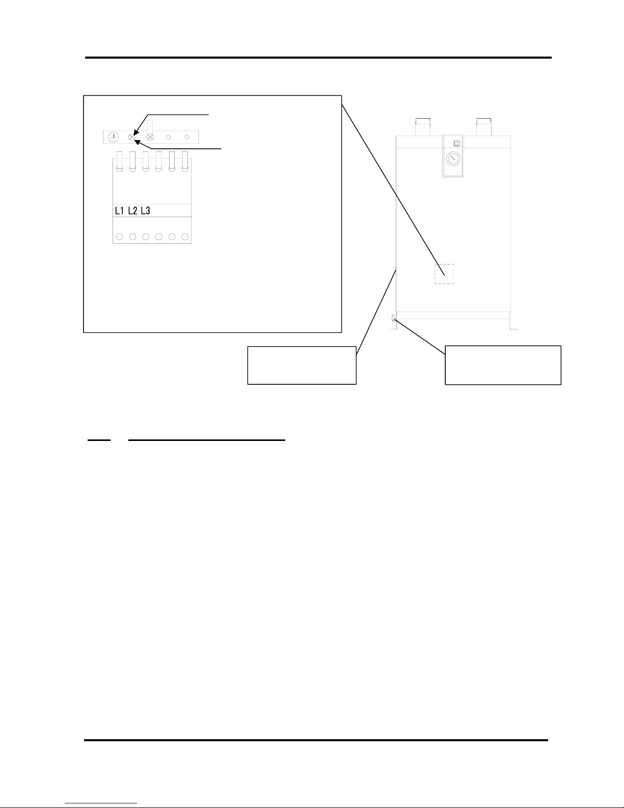
Air Dryer
12 Specification for Option T
12-5How to re-start the operation
12 - 3
IDX-OM-K021
Terminal block
Grommet
Signal code inlet
Rubber grommet
Power code inlet
12-5 How to re-start the operation
The output of the abnormal signal can be stopped by turning of f the switch with light. Remove the cause of
abnormal operation and leave it for 3 minutes or longer after the stopping the operation, and turn on the
switch with light to re-start.
The thermal relay
is still in operation if the output of the abnormal signal is not stopped even after the
switch with light is turned off. Refer to “5-2. How to reset the thermal relay and high pressure switch” in
the operation manual, and reset it.
Note) The high pressure switch can also be in operation for IDFB55E-46 and IDFB75E-46.
IDFB55E, 75E
321
Connections for customer
Another earth cable Connector width: 0.25inch (6.5mm) or less
Earth cable connector width: 0.4inch (10mm) or less
Power cord: AWG16
(1.25mm2) to AWG14 (2mm2)
Signal cord: AWG16
(1.25 mm2 ) to AWG14(2mm2)
Earth cable connection
Screw = M4×10
IDFB Series

Air Dryer
12 Specification for Option T
12-6Electric wiring diagram
12 - 4
IDX-OM-K021
12-6 Electric wiring diagram
CM
3
Failure
TDR
MC
C1
CN
For Option V
GFCI
21
Operation
MC
N
L
OLR
PE
For Option R
TB1
CN
P
MC
PRS
MC
TDR
ILS
TDR
C1
3
MC
21
MC
TDR
TDR
Failure
Operation
CM
CN
CN
P
For Option V
N
L
TB1
ILS
MC
TDR
PRS
PE
OLR
MC
GFCI
For Option R
CM
FM
PE
PE
PRR
PE
3
Failure
TDR
2
MC1
1
THR
Operation
MC1
MC2
GFCI
TB
P
R
S
2
MC2
MC1
MC1
EDV
P
2
1
W
W
P
T
ILS
PRS1
T
H
R
TDR
PRR
C01
TDR
記号 名称
CM Refrigerating Compressor
FM Fan Motor
FM1~6 Fan Motor
OLR Overload Relay
C1 Capacitor For Compressor Motor
C01 Capacitor For CM
ILS Switch with Lamp
PRS Pressure Switch
PRS1 Pressure Switch
PRS2 High Pressure Switch
TB Terminal Block
TB1 Terminal Block
TB2 Terminal Block
MC Magnetic Contactor
MC1 Magnetic Contactor
MC2 Magnetic Contactor
T Transformer
THR Thermal Relay
TDR Time Delay Relay
PRR Phase Reversal Relay
GFCI Ground Fault Circuit Interrupter
EDV Electronic Drain Valve
IDFB22E/37E-23 IDFB22E-11
IDFB Series
ForIDFB37E
IDFB55E/75E-46

Air Dryer
13 Specification for Option V
13-1Safety instructions
13 - 1
IDX-OM-K021
13 Specification for Option V
This product mounts the timer operated auto drain in Item 2 Specifications. When performing the
installation and maintenance work for the product, the following points must be understood and
followed. Additionally, read Item 3 for replacement work.
13-1 Safety instructions
When handling the product, take care to the following precautions.
13-2 Specifications
The timer is set to have ON time of 0.5sec and OFF time of 0.5min. at the time of shipment from the
factory. Do not change this timer setting. If it is changed, water could be discharged from the outlet
line of the dryer. Service parts number will change depending on the power supply voltage of the
dryer.
Warning
1. Do not remove the auto drain if air pressure remains of the product. When removing the
auto drain, stop the supply of air to the primary side of the product, exhaust the air from the
secondary side and ensure there is no residual pressure. If the air pressure is left at the
inside of the product, parts could suddenly pop out and cause accident when loosened.
2. Put gloves to prevent injury when removing the auto drain.
3. Operator could touch the drain waste from repalced auto drain. Follow the procedures
prepared by the customer to keep safety of operators. (Ex. Put protective goggles, apron
and/or gloves to protect body from toucing the drain waste for replacement worken
replacing the product.)
Warning
Only qualified person must perform wiring.
1. Provide the power suitable for the product specifications.
2. Be suer to ground the product for the safety. Do not ground to water pipe, gas tube or
lightening rod line.
3. Do not connect too many wires to the same outlet, which could results in heat generation
and fire.
4. Do not retrofit the wiring of the dryer and the power supply line.
IDFB Series

Air Dryer
13 Specification for Option V
13-3How to perform maintenance
13 - 2
IDX-OM-K021
13-3 How to perform maintenance
The product needs to be maintained. Clean it in the following procedure periodically.
1) Close the ball valve.
2) Press the test switch and make the residual pressure zero.
3) Remove the strainer and clean it.
4) Reassemble the strainer and open the ball valve.
13-4 Electric circuit
For electric circuit, refer to ’’6-4 Electric circuit’’.
Please refer to ’’12-6 Electric circuit’’ when option T is included.
Power supply voltage of dryer
AC115V
AC230V
AC460V
Order number (service parts)
IDF-S0199
IDF-S0198
IDF-S0302
Max. operating pressure
240psig (1.6MPa)
Fluid
Drain
Power supply voltage of drain timer
AC115V±10%
(60Hz)
AC230V±10%
(60Hz)
AC230V±10%
(60Hz)
ON time
0.5sec
OFF time
0.5min
ON OFF
ON:SEC OFF:MIN
0.5
2
4
6
8
10
0.5
1
2
3
4
5
Built-in strainer
Ball valve
Test switch
Strainer lid
IDF-S0199 (AC115V)
IDF-S0198 (AC230V)
KQ2L11-04S (Thread Symbol"N")
KQ2L10-04S (Thread Symbol"None")
3/8 (Thread Symbol"N")
φ 10 (Thread Symbol"None")
IDF-S0302 (AC230V)
IDFB Series

Air Dryer
14 Service Record
14-1Service Record
14 - 1
IDX-OM-K021
14 Service Record
14-1 Service Record
It is recommended to keep a maintenance/service record.
Parts No.
Description
Maintenance/Service Work Description
Date
IDFB Series

Akihabara UDX 15F,
4-14-1, Sotokanda, Chiyoda-ku, Tokyo 101-0021, JAPAN
Tel: +81 3 5207 8249 Fax: +81 3 5298 5362
URL: http://www.smcworld.com
Specifications are subject to change without prior notice and any obligation the part of the manufacturer.
2017 SMC Corporation All Rights Reserved
 Loading...