

SMC Networks IDFB3E-11, IDFB4E-11, IDFB6E-11, IDFB8E-11, IDFB11E-11 Operation Manual
...
IDX-OM-J001-E
Initial issue April, 2005
5th edition January, 2011
PRODUCT NAME
Refrigerated Air Dryer
MODEL / Series
IDFB3E-11 -A
IDFB4E-11 -A,R,T,V
IDFB6E-11 -A,K,R,T,V
IDFB8E-11 -A,K,R,T,V
IDFB11E-11 -A,K,R,T,V
IDFB15E-11 -K,R,T,V
Please read this manual prior of using the air dryer. Keep the manual readily available for
reference.
© 2011 SMC CORPORATION All Rights Reserved.
Operation Manual

Dear Customers
Thank you for selecting SMC Refrigerated Air Dryer.
This operation manual must be read and understood thoroughly before using the equipment. It provides all
essential information pertaining to safety, as well as, maximizing equipment efficiency in order to extend the life of
the equipment.
In addition, it is strongly recommended that you follow all the safety guidelines and regulations set forth by the
local government agency for proper installation and usage.
This manual explains about installation and trial operation of the equipment. These tasks should be performed
only by individuals with the proper training and have a good understanding of the air dryer.
There is no production amends or financial compensation due to dryers trouble.
This manual contains confidential information proprietary to SMC. It must not be reproduced or disclosed to
others, or used in any other way, in part or in whole, except as authorized in writing by SMC.
Caution: Please understand that the contents of this operation manual are subjected to
change without prior notice.
Table of Contents
Table of Contents - 1
To Customers
Chapter i Safety Instructions
i - 1 Warning: Before Using Air Dryer ..........................................................i - 1
i - 1 - 1 Hazard, Warning, and Caution Used in This Manual .....................................i - 1
i - 2 Danger Classifications/Position of Hazard warning Label........i - 2
i - 2 - 1 Danger Classifications....................................................................................i - 2
i - 2 - 2 Hazard of Electricity .......................................................................................i - 3
i - 2 - 3 Hazard of Hot Surface....................................................................................i - 3
i - 2 - 4 Hazard of Rotating Fan Motor........................................................................i - 3
i - 2 - 5 Danger of Compressed Air Circuit..................................................................i - 3
i - 2 - 6 Positions of Hazard Warning Label................................................................i - 4
i - 2 - 7 Hazard of Refrigerant.....................................................................................i - 5
i - 2 - 8 Cautions about Usage....................................................................................i - 6
i - 2 - 9 Other Label.....................................................................................................i - 6
i - 3 Disposal...........................................................................................................i - 7
Chapter 1 Parts Name and Functions
1 - 1 Parts Names and Functions ................................................................. 1 - 1
Chapter 2 Transportation / Installation
2 - 1 Transportation ............................................................................................ 2 - 1
2 - 2 Installation.................................................................................................... 2 - 2
2 - 2 - 1 Location........................................................................................................ 2 - 2
2 - 2 - 2 Tie Down ...................................................................................................... 2 - 3
2 - 2 - 3 Air piping ...................................................................................................... 2 - 3
2 - 2 - 4 Drain Tube.................................................................................................... 2 - 3
2 - 2 - 5 Electric Wiring .............................................................................................. 2 - 4
2 - 3 Cautions about reinstallation............................................................... 2 - 6
Chapter 3 Operation / Shutdown
3 - 1 Check points before operation
............................................................ 3 - 1
3 - 2 Operation ...................................................................................................... 3 - 1
3 - 3 Shutdown...................................................................................................... 3 - 2
3 - 4 Cautions about restart ............................................................................ 3 - 2
3 - 5 Check points before restart .................................................................. 3 - 2
Chapter 4 Maintenance
4 - 1 Daily inspection ......................................................................................... 4 - 1
4 - 2 Periodical maintenance .......................................................................... 4 - 1
Chapter 5 Troubleshooting.............................................................................................. 5 - 1
Chapter 6 References
6 - 1 Specifications ............................................................................................. 6 - 1
6 - 2 Dimensions .................................................................................................. 6 - 2
6 - 3 Electrical Circuit ........................................................................................ 6 - 4
6 - 4 Compressed Air and Refrigerant Circuit / Operation Principles ..... 6 - 5
6 - 5 Service Parts List ...................................................................................... 6 - 6
Table of Contents

Table of Contents
Table of Contents - 2
Chapter 7 Specification for Option A
7 - 1 Safety instructions.................................................................................... 7 - 1
7 - 2 Specification................................................................................................ 7 - 1
7 - 3 Air piping ...................................................................................................... 7 - 1
7 - 4 Dryer specifications ................................................................................. 7 - 1
Chapter 8 Specification for Option K
8 - 1 Safety instructions.................................................................................... 8 - 1
8 - 2 Specifications ............................................................................................. 8 - 2
Chapter 9 Specification for Option R
9 - 1 Safety instructions.................................................................................... 9 - 1
9 - 2 Specifications of GFCI ............................................................................ 9 - 2
9 - 3 How to connect the power supply ..................................................... 9 - 2
Chapter 10 Specification for Option T
10 - 1 Safety instructions
.................................................................................. 10 - 1
10 - 2 Specifications ........................................................................................... 10 - 1
10 - 3 Remote operation................................................................................... 10 - 2
10 - 4 How to connect the power supply and signal cable................ 10 - 2
10 - 5 Electric circuit........................................................................................... 10 - 3
Chapter 11 Specification for Option V
11 - 1 Safety instructions...................................................................................11 - 1
11 - 2 Specifications ............................................................................................11 - 1
11 - 3 How to perform maintenance..............................................................11 - 2
Chapter 12 Service Record
12 - 1 Service Record......................................................................................... 12 - 1
i Safety Instructions
i - 1
i Safety Instructions
Be sure to read and comprehend important cautionary
notifications in this operation manual before use
i-1 Warning: Before Using Air Dryer
In this chapter, the stated contents are especially about safety.
This Air Dryer is installed downstream of the air compressor to remove moisture. The manufacturer is not
responsible for any misuses or misapplications.
This air dryer operates with high voltage and hot surfaces during operation. In addition, this air dryer
has high speed rotating fan and motor, which can cause serious injury upon accidental contact. It is
advised that you contact the factory or SMC authorized dealer for spare parts or other servicing needs.
We strongly recommend that any one who is working with this air dryer need to read and understand the
instructions in this manual beforehand. Often, it’s necessary for the people involved, to receive training
in order to address the issues of safety and proper application.
When short period power shortage (including instantly recovered shortage) is recovered, it may take a
longer starting period than usual starting or may not start due to the protective devices.
In this case, turn off the ON-OFF switch on dryer panel and wait 3 minutes. After this step, turn on the
switch to restart. Whenever open the cover panel of this unit, do not miss to turn off the ON-OFF switch,
because dryer may start itself when the power supply is recovered.
Connections to a power source where the equipment is exposed to transient stresses exceeding
overvoltage category II (as defined in IEC60664-1).
Only connect to TN-S power distribution systems with N conductively connected to PE.
i-1-1 Hazard, Warning, and Caution Used in This Manual
This equipment is designed with the first priority on safety. However, there are some inherent risks
that cannot be eliminated. This manual classifies these risks into the following three categories
according to the severity: DANGER, WARNING and CAUTION. Read the warning statements
carefully and thoroughly understand them before operating or performing maintenance on the unit.
DANGER
“DANGER” indicates that there is an imminence hazard that will cause serious
injury or death if not avoided.
Do not operate the equipment without the cover panel.
WARNING
“WARNING” indicates that there is a hazard that may cause serious injury or
death if not avoided.
CAUTION
“CAUTION” indicates that there is a hazard that may cause minor injury.
i Safety Instructions
i - 2
i-2 Danger Classifications & Position of Hazard warning Labels
To help you recognize the hazards, the unit utilizes special graphics to indicate different hazards. Confirm the
contents of the hazards and the location of the labels before operation.
Warning
• Only properly trained, qualified personnel are allowed to perform tasks such as:
Operation, installation, relocation of equipment and maintenance works.
• Should any problem occurs, address it according to instruction in this manual.
• Identify problems following the guidelines in Chapter 5 for Troubleshooting before
proceed with maintenance works.
• The equipment should not be turn on in the event of any problems.
When the equipment gets out of order, shutdown immediately, and contact for
service
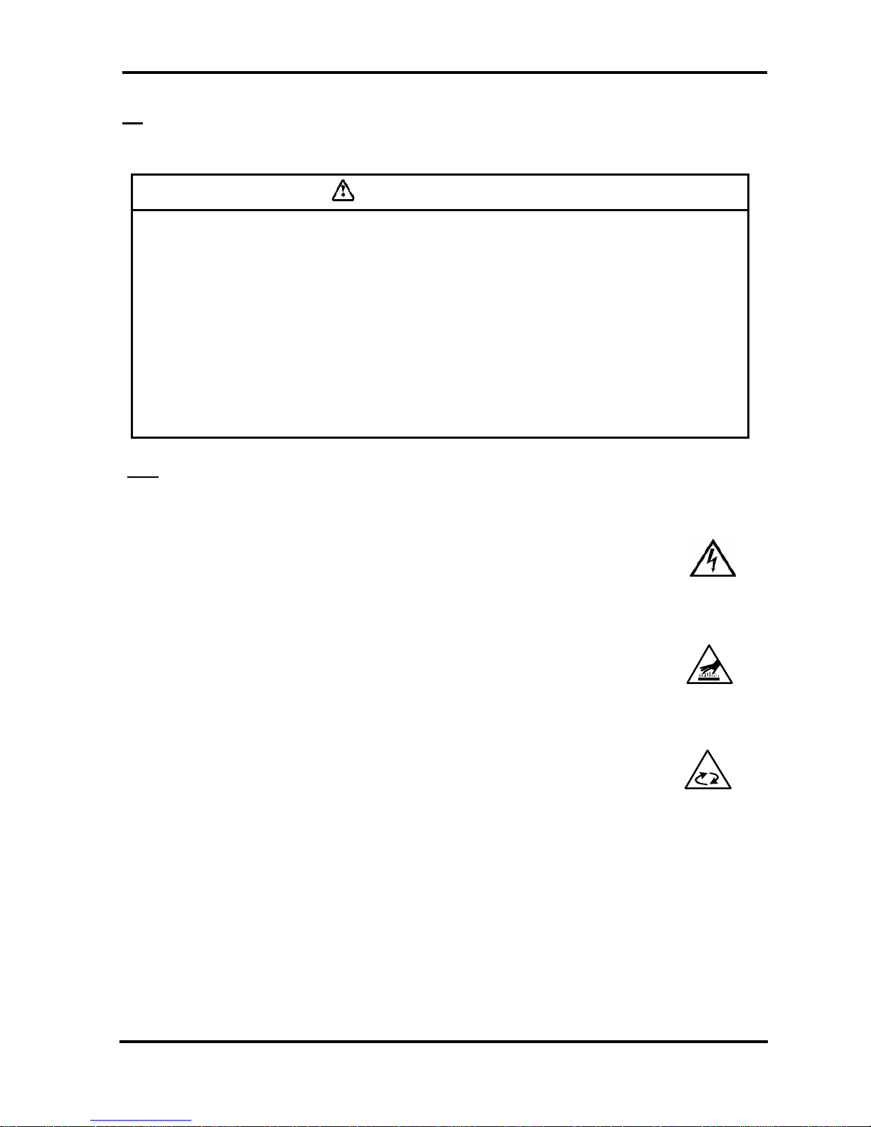
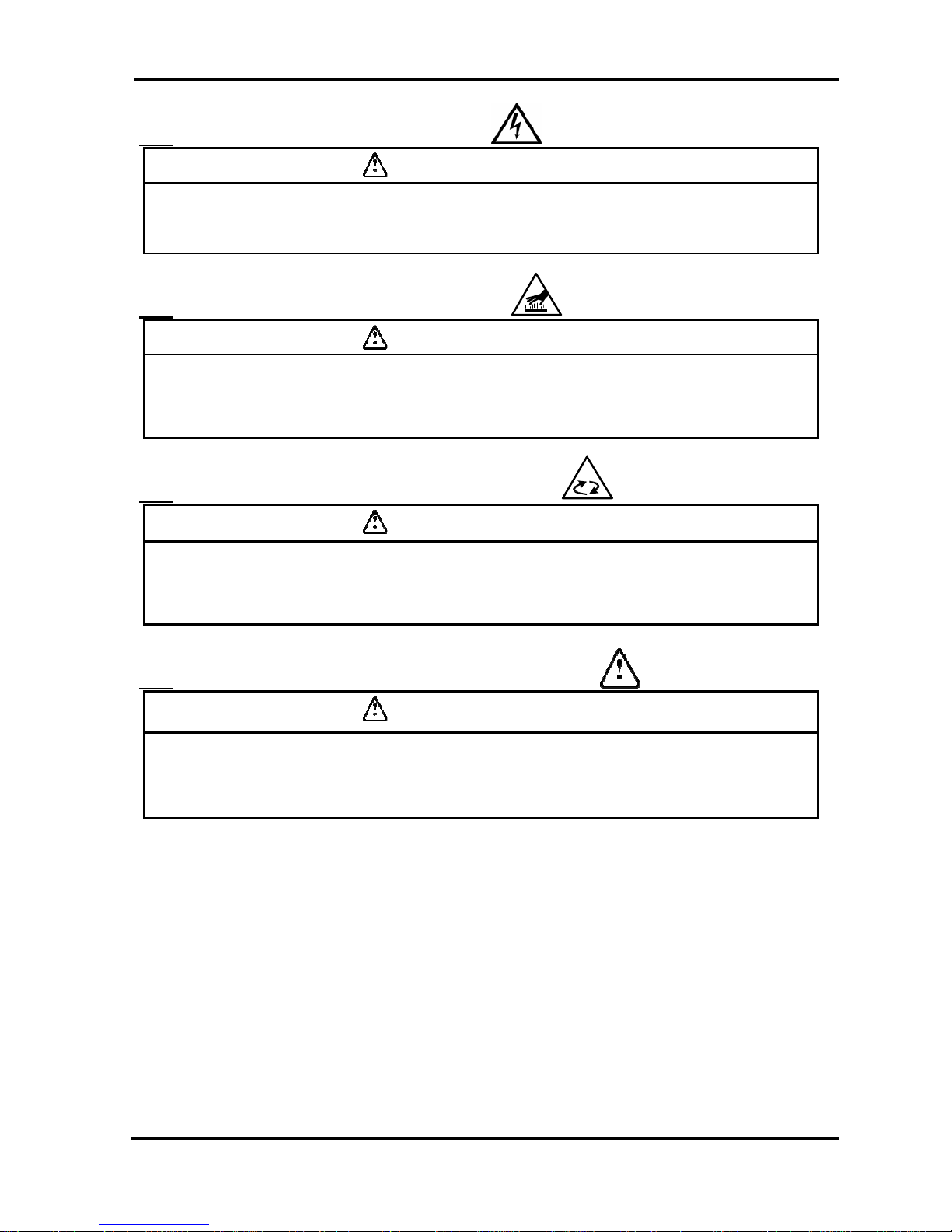
i-2-1 Danger Classifications
Specific danger classification of this equipment is as follows.
Hazard of Electricity
Since this equipment operates with high voltage, there is the danger of electric
shock. This special symbol is used, along with key words: “CAUTION”, “WARNING”
or “DANGER”, on the equipment and in this manual.
Hazard of Hot Surface
Since this equipment becomes hot while running, there is the danger of burn injury.
This special symbol is used, along with key words: “CAUTION”, “WARNING” or
“DANGER”, on the equipment and in this manual.
Hazard
of Rotor
Since this equipment has parts that rotate at high speed while running, there is the
danger of bodily injury. This special symbol is used, along with key words: “CAUTION”,
“WARNING” or “DANGER”, on the equipment and in this manual.
i Safety Instructions
i - 3
i-2-2 Hazard of Electricity
Warning
Inside of this equipment, there is a power-supplying section with high voltage
separated by the cover panel. Do not operate the equipment with the cover panel off.
i-2-3 Hazard of Hot Surface
Warning
Since this equipment has parts that become hot during operation, there is the danger
of burn-associated injuries. These parts remain hot even after power is off. Wait until
the unit has cooled down before touching.
i-2-4 Hazard of Rotating Fan Motor
Warning
Since this equipment has parts that rotate during operation, there is the danger of
injury resulting from direct contact. The fan and rotor will start/stop automatically.
Thus, do not work on them when power is on.
i-2-5 Danger of Compressed Air Circuit
Warning
Before replacing or cleaning parts, be sure to relief the pressure remained inside of the
equipment until the gauge indicates “0”. High pressure can propel object at high
velocity and cause injury.
i Safety Instructions
i - 4
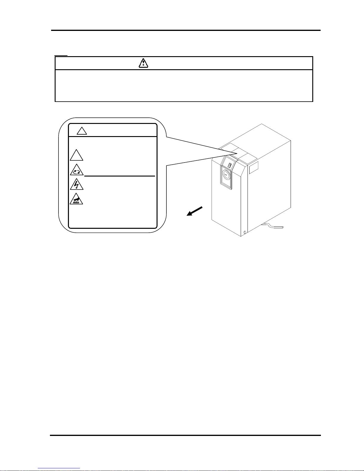
i-2-6 Positions of Danger Warning Label
Warning
Read with caution and pay attention to the notations of danger warning labels.
Do not remove or rub danger warning labels.
Confirm the positions of danger warning labels.
Front
WARNING 警告
!
1 Remove panels for maintenance only.
2 Never insert anything i nto product to ensure
safety.
3 Cut power prior to maintenance to prevent
electric shock.
4 Settle product to room temp.before main tenance toprevent burn or fro stbite.
5 Ensure zero air pressu re before replacing parts.
1 点検以外はパネルを取り外さないこと。
2 回転物があるので指、棒状の物を差し
込まないこと。
3 感電の恐れがあるので、点検の前には電源を
切ること。
4 火傷の恐れがあるので、点検の前には装置を
常温にすること。
5 部品交換の前には必ず、空気圧力を"0"に
すること。
!
i Safety Instructions
i - 5
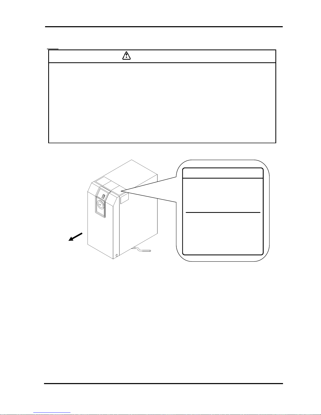
Front
i-2-7 Hazard of Refrigerant
Caution
This equipment uses Fluorocarbon (HFC) as a refrigerant.
It is strictly forbidden to emit Fluorocarbon into the atmosphere. Before you repair the
refrigerant circuit, you should collect the refrigerant with proper evacuation system.
The collected refrigerant should be properly recycled by qualified agency. Only
personnel with proper credential are allowed to handle refrigerant.
Only properly trained qualified personnel are allowed to remove the cover panel of the
equipment.
The quantity and the type of Fluorocarbon are mentioned on the specification label.
Fluorocarbon Collection and Destruction Law in Japan
フロン回収破壊法第一種特定製品
This product uses
Fluorocarbon (HFC) as a refrigerant.
1 It is strictly forbidden to emit Fluorocarbon
to the atmosphere.
2 When disposing this product, Fluorocarbon
must be collected in an appropriate manner.
3 The kind of Fluorocarbon and the amount used
in this product is prited on the name label.
この製品には冷媒として、
フロン類(HFC)が使われています。
1 フロン類をみだりに大気中に放出することは
禁じられています。
2 この製品を廃棄する場合には、フロン類の回収が
必要です。
3 フロン類の種類及び数量は、型式銘板に記載
されています。
i Safety Instructions
i - 6
i-2-8 Cautions about Usage
Warning
Please follow the instructions on all warning labels. Do not remove or deface
warning labels, and confirm the location of warning labels.
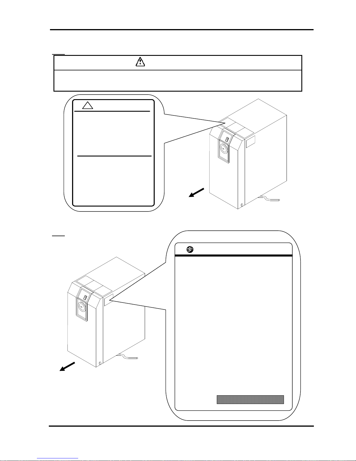
i-2-9 Other Label
Front
Front
CAUTION 注意
!
1 Read manual before operation.
2 Ensure van tilation and maintenance
space.
3 Keep water away from the product.
4 Secur e In / Out connector w ith spanner
during piping.
5 Wait 3 minutes before restart.
6 Ensure Running Condition / Evaporating
Temp . in green zone.
1 ご使用前に必ず取扱説明書を読んでください。
2 通風、メンテナンススペースを確保して
ください 。
3 雨や水滴がかからないようにしてください。
4 IN/OUTポートをスパナで固定して
配管 して ください 。
5 再起動は運転停止3分後に行ってください。
6 RUNNING CONDITION・蒸発温度計は
グリーン帯で使用してください。
SMC AIR DRYER
MODEL
VOLTAGE
RATED CURRENT
MCA
MOPD
CMP LRA
AIR FLOW RATE
MAX. INLET PRESS.
MAX. INLET TEMP.
MAX.AMBIENT TEMP
MIN. AMBIENT TEMP
REFRIGERANT
LO. SIDE PRESS.
HI. SIDE PRESS.
WEIGHT
SERIAL No.
MAKER
*12456789*
i Safety Instructions
i - 7
i-3 Disposal
When you dispose of the equipment, you should collect the refrigerant and the refrigerant oil inside the
refrigerant circuit.
Caution
This equipment contains Fluorocarbon HFC.
It is strictly forbidden to emit Fluorocarbon into the atmosphere. Before you
repair the refrigerant circuit, you should collect the refrigerant with proper
evacuation system. The collected refrigerant should be properly recycled by
qualified agency. Only personnel with proper credential are allowed to
handle refrigerant.
Only properly trained and qualified personnel are allowed to remove the
cover panel of the equipment.
The quantity and the type of Fluorocarbon are mentioned on the
specification label.
Caution
Dispose of the refrigerant and refrigerant oil according to the regulation of
local government.
Only personnel with proper credential are allowed to collect refrigerant and
refrigerant oil.
Only properly trained and qualified personnel are allowed to remove the
cover panel of the equipment.
For any questions, please contact our factory or SMC authorized dealers.
1 Name and Functions Parts
1 - 1
1 Parts Name and Functions
1-1
Parts Name and Functions
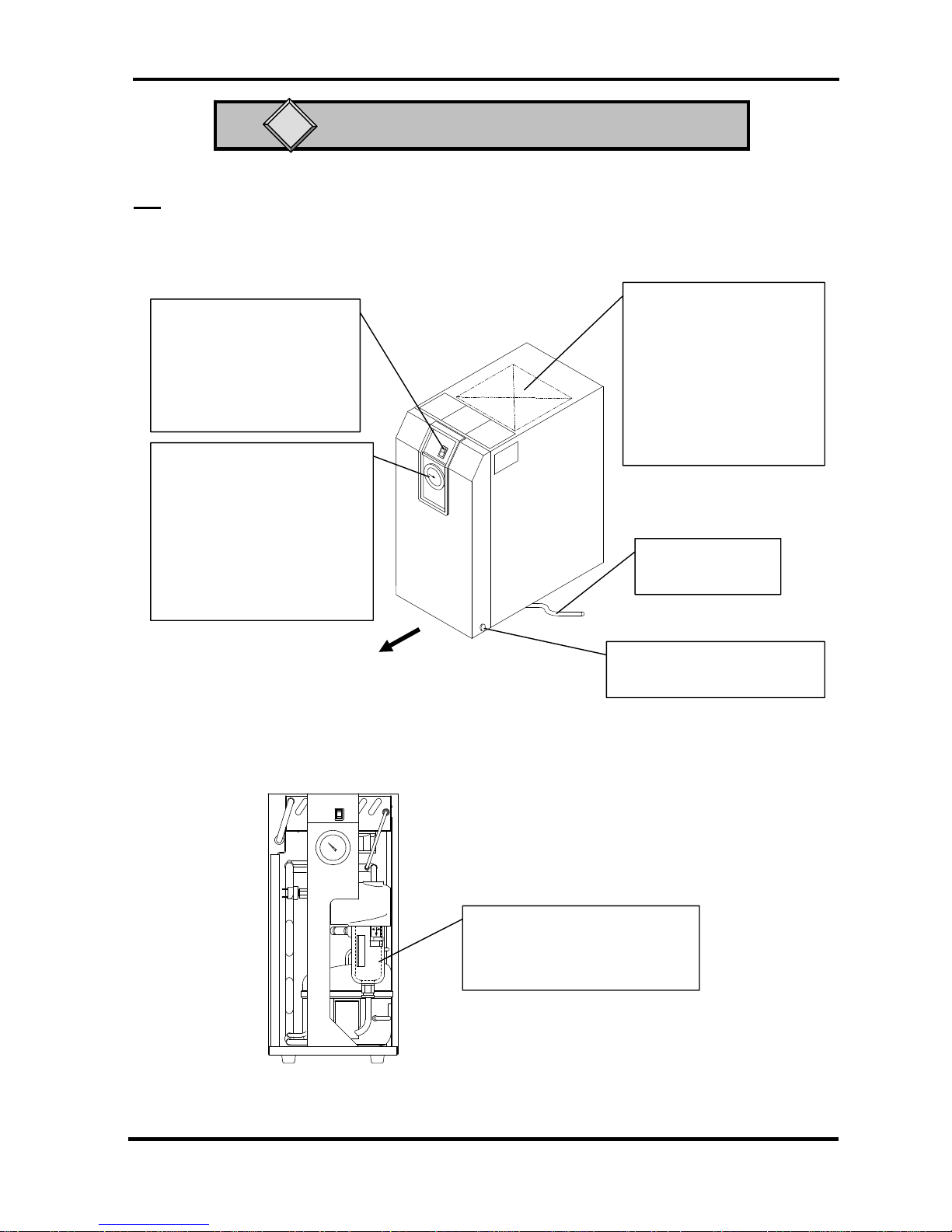
• IDFB3E
Front
Switch with Lamp
(ON/OFF Switch)
The lamp is continuously ON
during normal operation. Use it
for ON/OFF operations.
Evaporation thermometer
(EVAPORATING TEMP)
Indicates the temperature of
refrigerant of low-pressure
side.
During normal driving, it
indicates in the green zone.
Drain Tube
Discharges drain.
Auto Drain
It is covered with insulator, which
should not be removed.
No Front Panel
Top Ventilation Grille
(Outlet)
Hot air will be exhausted
from condenser by fan. No
obstacles shall be allowed
to place on top of it or even
close the grille.
Panel Lock
Another one is on the left side.
1 Name and Functions Parts
1 - 2
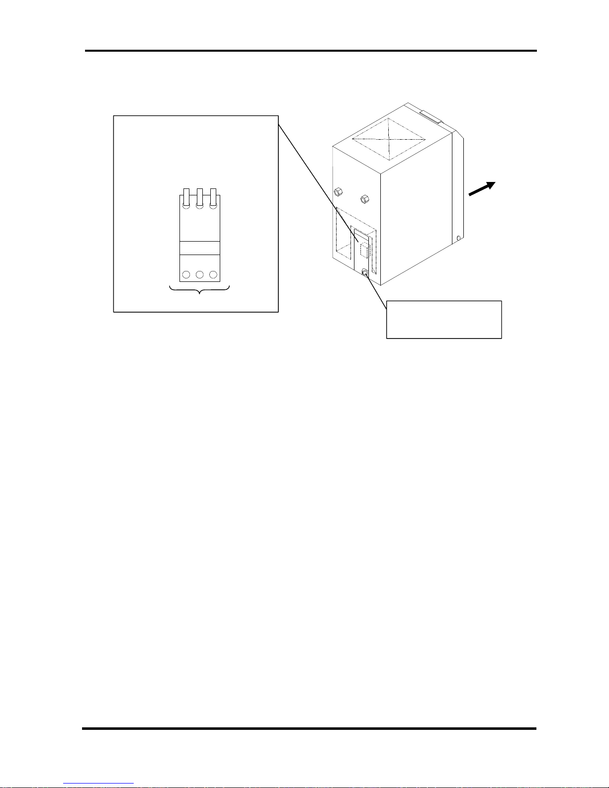
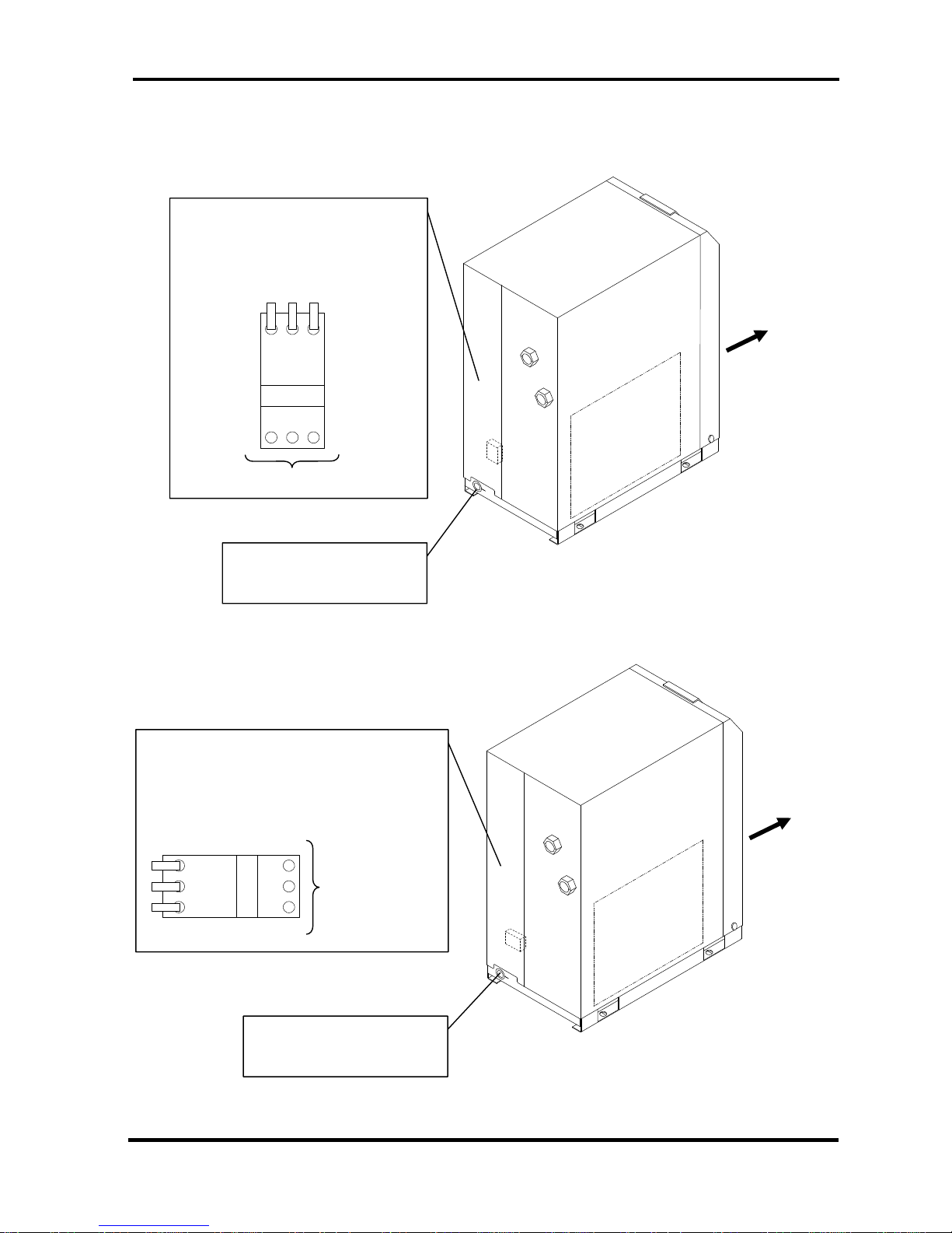
• IDFB3E
Membrane Grommet
Power cord outlet
Front
Electrical Terminal Cover
You can see the terminal block when
you remove this cover. Connect the
power cable through the membrane
grommet.
Customer Connection Side
L N PE
1 Name and Functions Parts
1 - 3
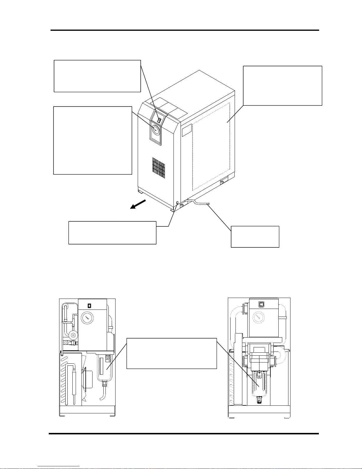
• IDFB4E to 15E
Front
Switch with Lamp
The lamp is continuously ON
during normal operation.
Evaporation Thermometer
Indicates the evaporating
temperature of refrigerant on
low-pressure side.
During normal operation, the
indicator remains in the
green zone.
Ventilation Grille
Hot air will be exhausted by
condenser fan. Do not block
these vents.
Panel Set Screw (x 2)
Another one is on opposite side
Drain Tube
Discharges drain.
V
iew with Front Panel removed
IDFB4E to 11E
Auto Drain
Do not remove the insulation on
the auto drain.
IDFB15E
1 Name and Functions Parts
1 - 4
• IDFB4E to 11E
• IDFB15E
Membrane Grommet
Power cord inlet
Front
Rear Panel
You can see the terminal block when you
remove this cover. Connect the power
cable through the membrane grommet
.
Customer Connection Side
L N PE
Membrane Grommet
Power cord inlet
Front
Rear Panel
You can see the terminal block when you remove
this cover. Connect the power cable through the
membrane grommet.
Customer
Connection Side
L
N
PE
 Loading...