

SMC Networks IDFA4E-23-C, IDFA4E-23-L, IDFA3E-23-C, IDFA4E-23-A, IDFA4E-23-R Operation Manual
...
IDFA3E-TFK17GB-A
IDX-OM-I070-G
Initial issue December, 2004
7th edition November, 2011
Original Instructions
PRODUCT NAME
Refrigerated Air Dryer
MODEL / Series
IDFA3E-23-A,C
IDFA4E-23-A,C,L,R,T,V
IDFA6E-23-A,C,K,L,R,T,V
IDFA8E-23-A,C,K,L,R,T,V
IDFA11E-23-A,C,K,L,R,T,V
IDFA15E-23-C,K,L,R,T,V
Please read this manual prior of using the air dryer. Keep the manual readily available for
reference.
© 2016 SMC CORPORATION All Rights Reserved.
Operation Manual

Dear Customers
Thank you for selecting SMC Refrigerated Air Dryer.
This operation manual must be read and understood thoroughly before using the product. It provides all essential
information pertaining to safety, as well as, maximizing product efficiency in order to extend the life of the product.
In addition, it is strongly recommended that you follow all the safety guidelines and regulations set forth by the
local government agency for proper installation and usage.
This manual explains about installation and trial operation of the product. These tasks should be performed only
by individuals with the proper training and have a good understanding of the air dryer.
There is no production amends or financial compensation due to dryers trouble.
This manual contains confidential information proprietary to SMC. It must not be reproduced or disclosed to
others, or used in any other way, in part or in whole, except as authorized in writing by SMC.
Note: The contents of this operation manual are subjected to change without prior notice.
This product conforms with the following directive(s):
Machinery Directive 2006/42/EC
EMC Directive 2004/108/EC
Directive
Table of Contents
Table of Contents - 1
To Customers
Chapter i Safety Instructions
i - 1 Warning: Before Using Air Dryer ......................................................... i - 1
i - 1 - 1 Hazard, Warning, and Caution Used in This Manual .................................... i - 1
i - 2 Danger Classifications/Position of Hazard warning Label........ i - 2
i - 2 - 1 Danger Classifications .................................................................................. i - 2
i - 2 - 2 Hazard of Electricity ..................................................................................... i - 3
i - 2 - 3 Hazard of Hot Surface .................................................................................. i - 3
i - 2 - 4 Hazard of Rotating Fan Motor ...................................................................... i - 3
i - 2 - 5 Danger of Compressed Air Circuit ................................................................ i - 3
i - 2 - 6 Positions of Hazard Warning Label............................................................... i - 4
i - 2 - 7 Hazard of Refrigerant ................................................................................... i - 5
i - 2 - 8 Cautions about Usage .................................................................................. i - 6
i - 2 - 9 Other Label .................................................................................................. i - 6
i - 3 Disposal ....................................................................................................... i – 7
i - 4 Limited warranty and Disclaimer / Compliance Requirements ........ i – 8
Chapter 1 Parts Name and Functions
1 - 1 Parts Names and Functions ................................................................ 1 - 1
Chapter 2 Transportation / Installation
2 - 1 Transportation .......................................................................................... 2 - 1
2 - 2 Installation .................................................................................................. 2 - 2
2 - 2 - 1 Location ..................................................................................................... 2 - 2
2 - 2 - 2 Anchorage .................................................................................................. 2 - 2
2 - 2 - 3 Air piping .................................................................................................... 2 - 2
2 - 2 - 4 Drain Tube .................................................................................................. 2 - 3
2 - 2 - 5 Electric Wiring ............................................................................................ 2 - 4
2 - 3 Cautions about reinstallation ............................................................. 2 - 5
Chapter 3 Operation / Shutdown
3 - 1 Check points before operation .......................................................... 3 - 1
3 - 2 Operation .................................................................................................... 3 - 1
3 - 3 Shutdown ................................................................................................... 3 - 2
3 - 4 Cautions about restart ........................................................................... 3 - 2
3 - 5 Check points before restart ................................................................. 3 - 2
3 - 6 Precautions for long-term non-operation ...................................... 3 - 2
Chapter 4 Maintenance
4 - 1 Daily inspection ....................................................................................... 4 - 1
4 - 2 Periodical maintenance ........................................................................ 4 - 1
4 - 2 - 1 Cleaning of ventilation grille (suction grille) ................................................. 4 - 1
4 - 2 - 2 Service parts .............................................................................................. 4 - 1
4 - 2 - 3 Cleaning of Auto Drain Strainer .................................................................. 4 - 1
Chapter 5 Troubleshooting ............................................................................................ 5 - 1
Table of Contents

Table of Contents
Table of Contents - 2
Chapter 6 References
6 - 1 Specifications ........................................................................................... 6 – 1
6 - 2 Refrigerant with GWP reference ....................................................... 6 - 1
6 - 3 Dimensions ................................................................................................ 6 - 2
6 - 4 Electrical Circuit ...................................................................................... 6 - 3
6 - 5 Compressed Air and Refrigerant Circuit / Operation Principles ..... 6 - 4
6 - 6 Service Parts List .................................................................................... 6 - 5
Chapter 7 Specification for Option A
7 - 1 Safety instructions .................................................................................. 7 - 1
7 - 2 Specification.............................................................................................. 7 - 1
7 - 3 Air piping .................................................................................................... 7 - 1
7 - 4 Dryer specifications ............................................................................... 7 - 1
Chapter 8 Specification for Option C
8 - 1 Safety instructions .................................................................................. 8 - 1
8 - 2 Precautions for the installation and handling of the product ......... 8 - 1
8 - 3 Specifications ........................................................................................... 8 - 1
Chapter 9 Specification for Option K
9 - 1 Safety instructions .................................................................................. 9 - 1
9 - 2 Specifications ........................................................................................... 9 - 2
Chapter 10 Specification for Option L
10 - 1 Safety instructions ................................................................................ 10 - 1
10 - 2 Specification............................................................................................ 10 - 1
10 - 3 Specification of heavy duty auto drain (ADH4000-04). ........... 10 - 2
10 - 4 Installation of heavy duty auto drain ............................................. 10 - 2
10 - 5 Maintenance ............................................................................................ 10 - 2
Chapter 11 Specification for Option R
11 - 1 Safety instructions ................................................................................. 11 - 1
11 - 2 Specifications of GFCI .......................................................................... 11 - 2
11 - 3 How to connect the power supply ................................................... 11 - 2
Chapter 12 Specification for Option T
12 - 1 Safety instructions ................................................................................ 12 - 1
12 - 2 Specifications ......................................................................................... 12 - 1
12 - 3 Remote operation ................................................................................. 12 - 2
12 - 4 How to connect the power supply and signal cable................ 12 - 2
12 - 5 Electric circuit ......................................................................................... 12 - 3
Chapter 13 Specification for Option V
13 - 1 Safety instructions ................................................................................ 13 - 1
13 - 2 Specifications ......................................................................................... 13 - 2
13 - 3 How to perform maintenance ........................................................... 13 - 2
Chapter 14 Service Record
14 - 1 Service Record ....................................................................................... 14 - 1
i Safety Instructions
i - 1
i Safety Instructions
Be sure to read and comprehend important cautionary
notifications in this operation manual before use
i-1 Warning: Before Using Air Dryer
In this chapter, the stated contents are especially about safety.
This Air Dryer is installed downstream of the air compressor to remove moisture. The manufacturer is not
responsible for any misuses or misapplications.
This air dryer operates with high voltage and hot surfaces during operation. In addition, this air dryer
has high speed rotating fan and motor, which can cause serious injury upon accidental contact. It is
advised that you contact the factory or SMC authorized dealer for spare parts or other servicing needs.
We strongly recommend that any one who is working with this air dryer need to read and understand the
instructions in this manual beforehand. Often, it’s necessary f or the people involved, to recei ve training
in order to address the issues of safety and proper application.
When short period power shortage (including instantly recovered shortage) is recovered, it may take a
longer starting period than usual starting or may not start due to the protective devices.
In this case, turn off the ON-OFF switch on dryer panel and wait 3 minutes. After this step, turn on the
switch to restart. When the cover panel of this unit is open, the ON/OFF switch must be in the off position,
because dryer may start itself when the power supply is recovered.
Connections to a power source where the product is exposed to transient stresses exceeding
overvoltage category II (as defined in IEC60664-1).
Only connect to TN-S power distribution systems with N conductively connected to PE.
i-1-1 Hazard, Warning, and Caution Used in This Manual
This product is designed with the first priority on safety. However, there are some inherent risks
that cannot be eliminated. This manual classifies these risks into the following three categories
according to the severity: DANGER, WARNING and CAUTION. Read these statements carefully
and thoroughly understand them before operating or performing maintenance on the unit.
DANGER
“DANGER” indicates that there is an imminent hazard that will cause serious
injury or death if not avoided.
Do not operate the product without the cover panel.
WARNING
“WARNING” indicates that there is a hazard that may cause serious injury or
death if not avoided.
CAUTION
“CAUTION” indicates that there is a hazard that may cause minor injury.
i Safety Instructions
i - 2
i-2 Danger Classifications & Position of Hazard warning Labels
To help you recognize the hazards, the unit utilizes special graphics to indicate different hazards. Confirm the
contents of the hazards and the location of the labels before operation.
Warning
Only properly trained, qualified personnel are allowed to perform tasks such as:
Operation, installation, relocation of product and maintenance works.
Should any problem occurs, address it according to instruction in this manual.
Identify problems following the guidelines in Chapter 5 for Troubleshooting before
proceed with maintenance works.
In the event of any problems the product should not be turned on. When the
product fails or a fault occurs, shutdown immediately, and contact for service
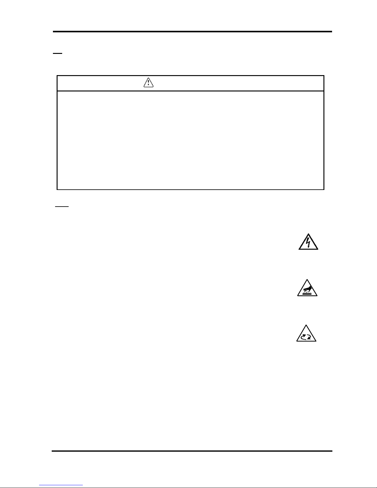
i-2-1 Danger Classifications
Specific danger classifications of this product are as follows.
Hazard of Electricity
Since this product operates with high voltage, there is the danger of electric
shock. This special symbol is used, along with key words: “CAUTION”, “WARNING”
or “DANGER”, on the product and in this manual.
Hazard of Hot Surface
Since this product becomes hot while running, there is the danger of burn injury.
This special symbol is used, along with key words: “CAUTION”, “WARNING” or
“DANGER”, on the product and in this manual.
Hazard of Rotating Object
Since this product has parts that rotate at high speed while running, there is the
danger of bodily injury. This special symbol is used, along with key words: “CAUTION”,
“WARNING” or “DANGER”, on the product and in this manual.

i Safety Instructions
i - 3
i-2-2 Hazard of Electricity
Warning
Inside of this product, there is a power-supplying section with high voltage separated
by the cover panel. Do not operate the product with the cover panel off.
i-2-3 Hazard of Hot Surface
Warning
Since this product has parts that become hot during operation, there is the danger of
burn-associated injuries. These parts remain hot even after power is off. Wait until the
unit has cooled down before touching.
i-2-4 Hazard of Rotating Fan Motor
Warning
Since this product has parts that rotate during operation, there is the danger of injury
resulting from direct contact. The fan and rotor will start/stop automatically. Thus, do
not work on them when power is on.
i-2-5 Danger of Compressed Air Circuit
Warning
Before replacing or cleaning parts, be sure to relief the pressure remained inside of the
product until the gauge indicates “0”. High pressure can propel object at high velocity
and cause injury.
i Safety Instructions
i - 4
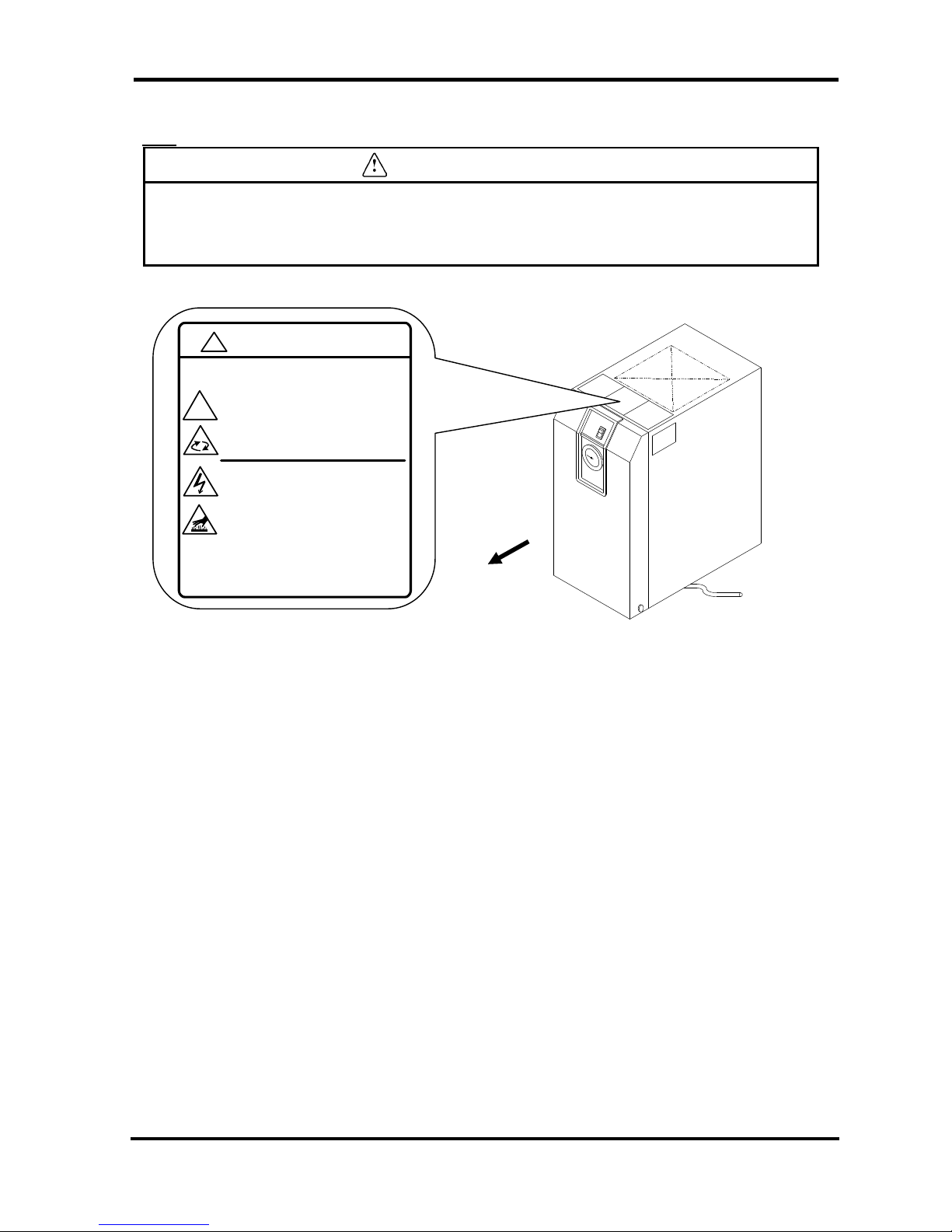
i-2-6 Positions of Danger Warning Label
Warning
Read with caution and pay attention to the notations of danger warning labels.
Do not remove or modify danger warning labels.
Confirm the positions of danger warning labels.
Front
WARNING 警告
!
1 Remove panels fo r maintenance only.
2 Never insert an ything into product to en sure
safety.
3 Cut power p rior to maintenance to prevent
electric sho ck.
4 Settle product to room temp.before main tenance topr event burn or frostbite.
5 Ensure zero air pressure before replacing parts.
1 点検以 外はパ ネルを取り 外さないこ と。
2 回転物 があるの で指、棒状 の物を 差し
込 まないこと。
3 感電の 恐れがあ るので、 点検の前 には電源を
切るこ と。
4 火傷の 恐れがあ るので、 点検の前 には装置を
常温 にすること 。
5 部品交 換の前に は必ず、 空気圧力を "0"に
するこ と。
!
i Safety Instructions
i - 5
Front
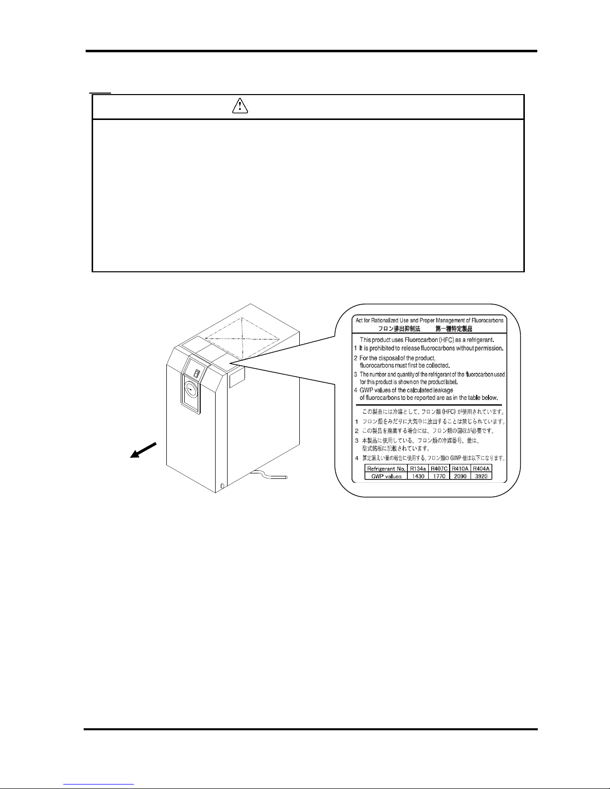
i-2-7 Hazard of Refrigerant
Caution
This product uses Fluorocarbon (HFC) as a refrigerant.
It is strictly forbidden to emit Fluorocarbon into the atmosphere. Before you repair the
refrigerant circuit, you should collect the refrigerant with proper evacuation system.
The collected refrigerant should be properly recycled by qualified agency. Only
personnel with proper credentials are allowed to handle refrigerant.
Only properly trained qualified personnel are allowed to remove the cover panel of the
product.
The quantity and the type of Fluorocarbon are mentioned on the specification label.
See Page i - 6.
i Safety Instructions
i - 6
i-2-8 Cautions about Usage
Warning
Please follow the instructions on all warning labels. Do not remove or deface
warning labels, and confirm the location of all warning labels.
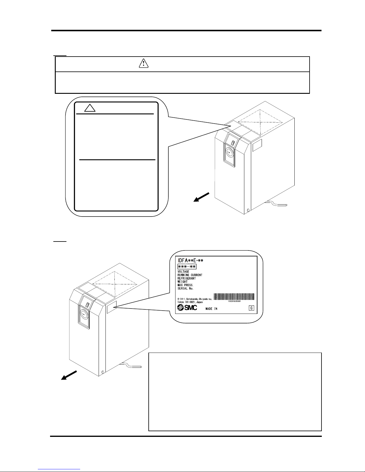
i-2-9 Other Label
Front
Contents
MODEL: Model
VOLTAGE: Power supply voltage (frequency)
RUNNING CURRENT: Running current
REFRIGERANT: Type of refrigerant (amount)
WEIGHT:Weight MAX.PRESS: Maximum operating pressure
SERIAL No.: Serial No.
MAKER:Maker
MADE IN: Country of manufacture
Front
CAUTION 注意
!
1 Read manual before operation.
2 Ensure vantilation and maintenance
space.
3 Keep water away from the product.
4 Secure In / Out connector with spanner
during piping.
5 Wait 3 minutes before restart.
6 Ensure Running Condition / Evaporating
Temp. in green zone.
1 ご使用 前に必ず取 扱説明書 を読んで ください。
2 通風、 メンテナンススペー スを確保 して
ください。
3 雨や水滴がかか らないよ うにしてく ださい。
4 IN/ OUTポートをス パナで固定して
配管してください。
5 再起動 は運転停 止3分後 に行ってくだ さい。
6 RU NNIN G CO NDIT ION・ 蒸発温度 計は
グリーン帯で使 用してくださ い。
CE
Specification Label
i Safety Instructions
i – 7
i-3 Disposal
When you dispose of the product, you should collect the refrigerant and the compressor oil inside the
refrigerant circuit.
Caution
This product contains Fluorocarbon HFC.
It is strictly forbidden to emit Fluorocarbon into the atmosphere. Before you
repair the refrigerant circuit, you should collect the refrigerant with proper
evacuation system. The collected refrigerant should be properly recycled by
qualified agency. Only personnel with proper credentials are allowed to
handle refrigerant.
Only properly trained and qualified personnel are allowed to remove the
cover panel of the product.
The quantity and the type of Fluorocarbon are mentioned on the
specification label. See Page i - 6.
Caution
Dispose of the refrigerant and compressor oil according to the regulation of
local government.
Only personnel with proper credential are allowed to collect refrigerant and
compressor oil.
Only properly trained and qualified personnel are allowed to remove the
cover panel of the product.
For any questions, please contact an SMC authorized dealers.
i Safety Instructions
i – 7
i - 4 Limited warranty and Disclaimer / Compliance Requirements
The product used subject to the following “Limited warranty and Disclaimer“ and “Compliance Requirements.
Read and accept them before using the product.
Limited warranty and Disclaimer
1. The warranty period of the product is 1 year in service or 1.5 years after the product is delivered.
Also, the product may have specified durability, running distance or replacement parts. Please consult
your nearest sales branch.
2. For any failure or damage reported within the warranty period which is clearly our responsibility, a
replacement product or necessary parts will be provided.
This limited warranty applies only to our product independently, and not to any other damage incurred
due to the failure of the product.
3. Prior to using SMC products, please read and understand the warranty terms and disclaimers noted in
the specified catalog for the particular products.
Compliance Requirements
1. The use of SMC products with production equipment for the manufacture of weapons of mass
destruction (WMD) or other weapon is strictly prohibited.
2. The exports of SMC products or technology from one country to another are govemed by the relevant
security laws and regulation of the countries involved in the transaction. Prior to the shipment of a SMC
product of a SMC product to another country, assure that all local rules goveming that export are known
and followed.
Caution
The Product is provided use in manufacturing industries.
The product herein described is basically provided for peaceful use in manufacturing industries.
If considering using the product in other industries, consult SMC beforehand and exchange
specifications or a contact if necessary.
If anything is unclear, contact your nearest sales branch.
1 Name and Functions Parts
1 - 1
1 Parts Name and Functions
1-1 Parts Name and Functions
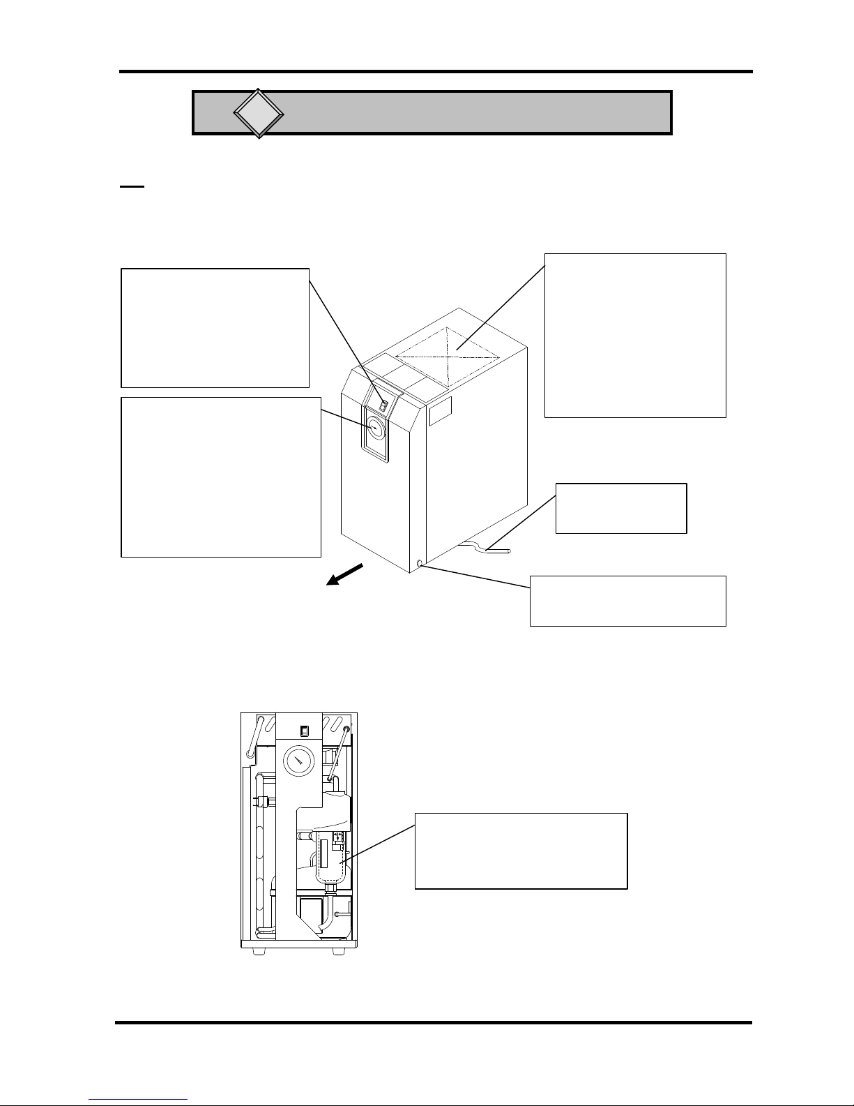
• IDFA3E
Front
Switch with Lamp
(ON/OFF Switch)
The lamp is continuously ON
during normal operation. Use it
for ON/OFF operations.
Evaporation thermometer
(EVAPORATING TEMP)
Indicates the temperature of
refrigerant of low-pressure
side.
During normal driving, it
indicates in the green zone.
Drain Tube
Discharges drain.
Auto Drain
It is covered with insulator, which
should not be removed.
No Front Panel
Top Ventilation Grille
(Outlet)
Hot air will be exhausted
from condenser by fan. No
obstacles shall be allowed
to place on top of it or even
close the grille.
Panel Lock
Another one is on the left side.
1 Name and Functions Parts
1 - 2
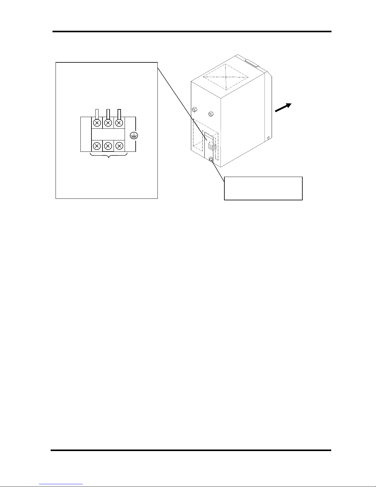
• IDFA3E
Membrane Grommet
Power cord outlet
Front
Electrical Terminal Cover
You can see the terminal block when
you remove this cover. Connect the
power cable through the membrane
grommet.
L
N
PE
Customer Connection Side
Terminal Connecting Screw: M3
Applied Pressure Terminal: 1.25-3
(Width 6.5mm and below)
( )
1 Name and Functions Parts
1 - 3
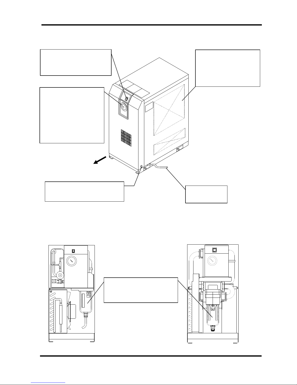
• IDFA4E to 15E
Front
Switch with Lamp
The lamp is continuously ON
during normal operation.
Evaporation Thermometer
Indicates the evaporating
temperature of refrigerant on
low-pressure side.
During normal operation, the
indicator remains in the
green zone.
Ventilation Grille
Hot air will be exhausted by
condenser fan. Do not block
these vents.
Panel Lock (x 2)
Another one is on opposite side
Drain Tube
Discharges drain.
Auto Drain
Do not remove the insulation on
the auto drain.
View with Front Panel removed
IDFA4E~11E
IDFA15E
 Loading...