

Page 1
IDX-OM-H006-H
Initial issue: January 2004
8th edition : November 2010
Operation Manual
PRODUCT NAME
Refrigerated Air Dryer
MODEL / Series
IDF1E-10
IDF2E-10
IDF3E-10 IDF3E-20
IDF4E-10 IDF4E-20
IDF6E-10 IDF6E-20
IDF8E-10 IDF8E-20
IDF11E-10 IDF11E-20
IDF15E-10 IDF15E-20
Please read this manual prior of using the air dryer. Keep the manual readily available for
reference.
© 2010 SMC CORPORATION All Rights Reserved.
Page 2

To Customers
Thanks for purchasing SMC Refrigerated Air Dryer.
This opertion manual must be read and understood throug houtly before handling. It provides all essential
information for maximizing product operating efficiency, as well as, for safe and longer life span operation.
For safety operation of SMC Refrigerat ed Air Drye r, read thor oughly and foll ow stated safety instructions, as well
as regulation stated within ISO 4414
*1
& JIS B 8370*2.
*1) ISO 4414: Pneumatic fluid power – Recomm endations for the applicatio n of equipment to transmission
and control systems.
*2) JIS B 8370: Pneumatic fluid power – General rules relati ng to systems
This manual explains about installation and operati on of the product. Only those who have thorough
understanding of the fundamental operating procedure or have basic knowledge and skills of handling industrial
product for the installation and operation of the product are qualified to perform installation and opera tion.
The contents of the operation manual and the other docume nts attached to t he product ca nnot become a part of
the contract clause or cannot chang e and modify exist ing agreement s, promises, an d relationship.
Any statements contained in the operation manual canno t be newly guaranteed and modify existing gua rantee
certificate.
You are not allowed to copy any part of this operation manual for usage of third pe rson without i nforming it to u s
beforehand.
Caution: Please understand that the contents of this operation manual are subject to
changed without previous notice.
Page 3

Air Dryer (IDF1E-10~IDF15E-10/20) T able of Contents
Table of Contents - 1
Table of Contents
To Customers
Chapter i Safety Instructions
i - 1 Warning: Before Using Air Dryer..........................................................i - 1
i - 1 - 1 Meanings of signs: Caution, Warning, Danger...............................................i - 1
i - 2 Danger Classifications / Position of Danger warning label......i - 3
i - 2 - 1 Danger Classifications....................................................................................i - 3
i - 2 - 2 Danger of Electricity.......................................................................................i - 4
i - 2 - 3 Danger of high Heat.......................................................................................i - 4
i - 2 - 4 Danger of Rotor..............................................................................................i - 4
i - 2 - 5 Danger of Compressed Air Circuit .................................................................i - 4
i - 2 - 6 Positions of Danger Warning Label................................................................i - 5
i - 2 - 7 Danger of Refrigerant.....................................................................................i - 6
i - 2 - 8 Cautions about Usage....................................................................................i - 7
i - 2 - 9 Other Label.....................................................................................................i - 7
i - 3 Disposal..........................................................................................................i – 8
i - 4 Limited warranty and Disclaimer / Compliance Requirements.........i – 9
Chapter 1 Parts Name and Functions
1 - 1 Parts Names and Functions ................................................................. 1 - 1
Chapter 2 Transport a tion / Installation
2 - 1 Transportation............................................................................................ 2 - 1
2 - 2 Installation.................................................................................................... 2 - 2
2 - 2 - 1 Location........................................................................................................ 2 - 2
2 - 2 - 2 Anchorage.................................................................................................... 2 - 2
2 - 2 - 3 Air piping ...................................................................................................... 2 - 2
2 - 2 - 4 Drain Tube.................................................................................................... 2 - 3
2 - 2 - 5 Electric wiring............................................................................................... 2 - 4
2 - 3 Cautions about reinstallation............................................................... 2 - 5
Chapter 3 Operation / Shutdown
3 - 1 Check points before operation............................................................ 3 - 1
3 - 2 Operation...................................................................................................... 3 - 1
3 - 3 Shutdown...................................................................................................... 3 - 2
3 - 4 Cautions about restart ............................................................................ 3 - 2
3 - 5 Check points before restart.................................................................. 3 - 2
3 - 6 Precautions for long-term non-operation....................................... 3 - 2
Chapter 4 Maintenance
4 - 1 Daily inspection ......................................................................................... 4 - 1
4 - 2 Periodical maintenance.......................................................................... 4 - 1
4 - 2 - 1 Cleaning of ventilation grille (suction grille).................................................. 4 - 1
4 - 2 - 2 Service parts.................................................................................................4 - 1
4 - 2 - 3 Cleaning of Auto Drain Strainer.................................................................... 4 - 1
Chapter 5 Troubleshooting.............................................................................................. 5 - 1
Chapter 6 References
6 - 1 Specifications.............................................................................................6 - 1
6 - 2 Dimensions.................................................................................................. 6 - 2
6 - 3 Electrical Circuit ........................................................................................ 6 - 3
6 - 4 Compressed Air and Refrigerant Circuit / Operation Principles.....6 - 5
Page 4
Air Dryer (IDF1E-10~IDF15E-10/20) i Safety Instructions
Safety Instructions
Before use, read and comprehend important
cautionary notification well on this operattion
manual.
i – 1 Warning: Before Useing Air Dryer
In this chapter, the stated contents are especially about safety way to use the product. for customer.
An Air Dryer is installed on the downstream of the air compressor to remove moisture. We, manufacturer, cannot
take any responsibility if you use it for any other purpose.
An Air Dryer works with high voltage and has some parts that gets hot or rotates during operation. Ask vendor if you
need component replacement and servicing.
Not only people handle the air dryer but every people who perform maintenance on or do works related to it shou ld
read safety instructions on this operation manual before handling.
This operation manual is not a general safety manual which is practiced b y safety training representatives.
People who handle this product or work around it need to take training to comprehand inherent risks of it and master
measures for safety.
It is usually responsible for super visor to follow the safety instructions, but each operator or maintemance
representative should do daily operatio ns on their own head.
Operators and maintemance representatives should take the safety of working plac e and work environment into
account.
It is necessary to think of the safety of working place and work environment for each task
Take enough safety training before the operation training. It is ver y dangerous to do operation t raining witho ut any
safety training. Operation training must be paid attention to its safet y.
Keep this operation manual handy for workers related to above contents to refer to anytime.
i – 1 – 1 Meaning of Signs: Caution, Warning, Danger
These safety instructions are intended to prevent hazardous situation and/or product damage.
These instructions indicate the level of potential hazard by signs “Caution”, “Warning” or
“Danger”. Contents with these signs st ate about important instructions conce rning safety. Confirm
where those signs are, and read and comprehend notices and cautionary notices well before
handling.
“Caution”, “Warning” or “Danger” is the order of importance (Danger>Warning>Caution). Followings
are the meanings of those signs.
Danger
Statements with the “Danger” sign explain about conditions in which there is a
possible result of serious injury or loss of life if someone handles wrongly during
operation or maintenance and did not follow the procedure to avoid danger.
i - 1
Page 5
Air Dryer (IDF1E-10~IDF15E-10/20) i Safety Instructions
Warning
Statements with the “Danger” sign explain about possibilities that can result in
serious injury or loss of life if someone handle wrongly during operation or
maintenance and did not follow the procedure to avoid danger.
Caution
Statements with the “Danger” sign explain about possibilities that can result in injury
or product damage if someone handles wrongly during operation or maintenance and
did not follow the procedure to avoid danger.
i - 2
Page 6

Air Dryer (IDF1E-10~IDF15E-10/20) i Safety Instructions
i – 2 Danger Classifications / Position of Danger Warning Label
To protect operator’s sefety, we group danger into some types uniquely and attached labels indicating those types.
Comfirm the contents of the danger types and positions of the labels before operation.
Warning
No one but professionals should operate an air dryer.
Transportation, installation, and maintenance involve risks. These should be done by
someone who have enough knowledge and experience about this product and incidental
devices.
No one but our service personnel or qualified person should open the cover panel of this
product.
Warning
Should any problem occur, address it according to statements on this manual.
• Identify problems according to “Chapter 5 Troubleshooting. ”
• Ask repair and maintenance.
Warning
The product should not be operated in the event of any problems.
When the product gets out of order, shutdown it immediatery, and contact our service
person or qualified person.
i-2-1 Danger Classifications
Specific danger classification of this product is as follows.
Danger of Electricity
Since this product runs at hign voltage, there is the danger of electric shock. So, we display a
symbol with indications,
“Caution”, “Warning” or “Danger,” on the product and this manual.
Danger of Heat
Since this product becomes hot while driving, there is the danger of burn injury. So, we display a
symbol with indications,
“Caution”, “Warning” or “Danger,” on the product and this manual.
Danger of Rotor
Since this product has parts that rotate while driving, there is the danger of catching your fingers in
or injury. So, we display a symbol with indications,
“Caution”, “Warning” or “Danger,” on the
product and this manual.
i - 3
Page 7
Air Dryer (IDF1E-10~IDF15E-10/20) i Safety Instructions
i – 2 – 2 Danger of Electricity
Inside of this product, there is power-supplying section with high voltage separated by the
cover panel. Do not operate the product without the cover panel.
No one but trained qualified person should operate or inspect in the power transmission
sections.
Warning
Read with caution and pay attention to the notations on danger warning labels.
Do not remove or rub danger warning labels.
Confirm the positions of danger warning labels.
i – 2 – 3 Danger of High Heat
Warning
Since this product has parts that become hot during operation, there is the danger of burn
injury resulting from contact with them. What is more, there is also the danger of burn injury due to
remaining heat after the power supply is cut. Therefore, wait until the t emperature of hot parts become
50
o
C and below.
i – 2 – 4 Danger of Rotor
Warning
Since this product has parts that rotate during operation, there is the danger of burn injury
resulting from contact with them. Though sometimes those parts can temporarily stop the rotation,
they will rotate again, and so do not work with them while driving.
i – 2 – 5 Danger of Compressed Air Circuit
Warning
Before replacing or cleaning parts, be sure to bleed compressed air remain inside of the
product untill the gauge indicates “0”. If you do not do this air-bleeding,
there would be the
great danger of unexpected accident, such as shooting out of parts when they are being unscrewed.
i - 4
Page 8
Air Dryer (IDF1E-10~IDF15E-10/20) i Safety Instructions
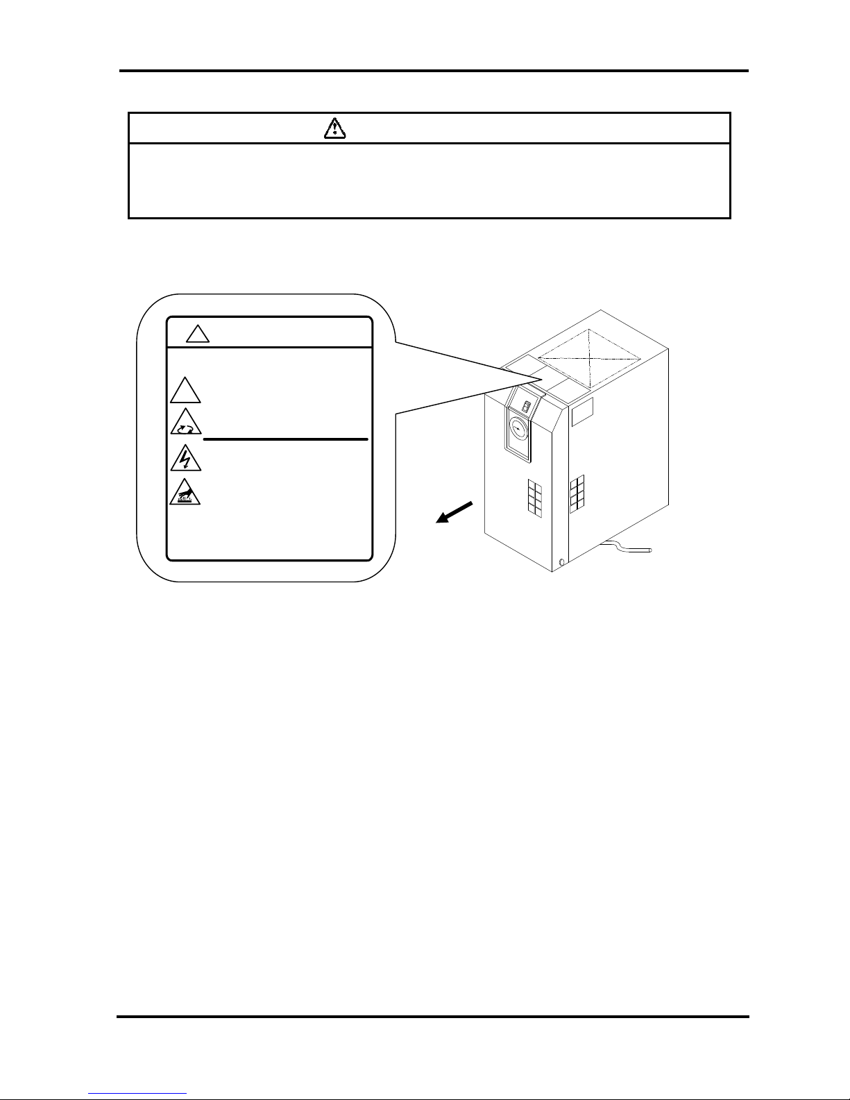
i – 2 – 6 Positions of Danger Warning Label
Warning
Read with caution and pay attention to the notations of danger warning labels.
Do not remove or rub danger warning labels.
Confirm the positions of danger warning labels.
Front
WARNING 警告
!
1 Remove panels for maintenance onl y.
2 Never insert anything into prod uct to ensu re
safety.
3 Cut power prior to maintenance to p revent
electric shock.
4 Settle product to room temp.before main tenance toprevent burn or frostbite.
5 Ensure zero air pr essure before replacing parts.
1 点検以外はパネルを取り外さないこと。
2 回転物があるので指、棒状の物を差し
込まないこと。
3 感電の恐れがあるので、点検の前には電源を
切ること。
4 火傷の恐れがあるので、点検の前には装置を
常温にすること。
5 部品交換の前には必ず、空気圧力を"0"に
すること。
!
i - 5
Page 9
Air Dryer (IDF1E-10~IDF15E-10/20) i Safety Instructions
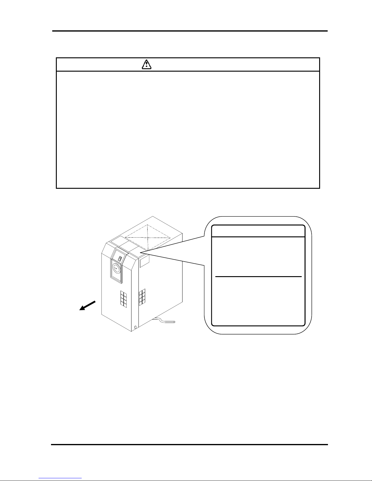
i – 2 – 7 Danger of Refrigerant
Caution
This product uses Fluorocarbon (HFC) as a refrigerant.
This product is specified by “Class 1 Fluorocarbon Collection and Destruction Law in
Japan.”
It is strictly forbitten to emit Fluorocarbon to the atmosphere. Before you repair this
product, you should collect the refrigerant with “Refrigerant collector.” Then, ask a
destruction agency to dispose of collected refrigerant. No one but someone have enough
knowledge and experience about the product and incidental device should do the collec tion
of the refrigerant.
No one but service person or qualified person should remove the cover panel of the
product.
The quantity and the sort of the Fluorocarbon are mentioned on the specification label that
are explained on Page i – 8.
Fluorocarbon Collection and Destruction Law in Japan
フロン回収破壊法第一種特定製品
This product uses
Fluorocarbon (HFC) as a refrigerant.
1 It is strictly forbidden to emit Fluorocarbon
to the atmosphere.
2 When disposing this product, Fluorocarbon
must be collected in an appropriate manner.
3 The kind of Fluorocarbon and the amount used
in this product is prited on the name label.
この製品には冷媒として、
フロン類(HFC)が使われています。
1 フロン類をみだりに大気中に放出することは
禁じられています。
2 この製品を廃棄する場合には、フロン類の回収が
必要です。
3 フロン類の種類及び数量は、型式銘板に記載
されています。
Front
i - 6
Page 10
Air Dryer (IDF1E-10~IDF15E-10/20) i Safety Instructions
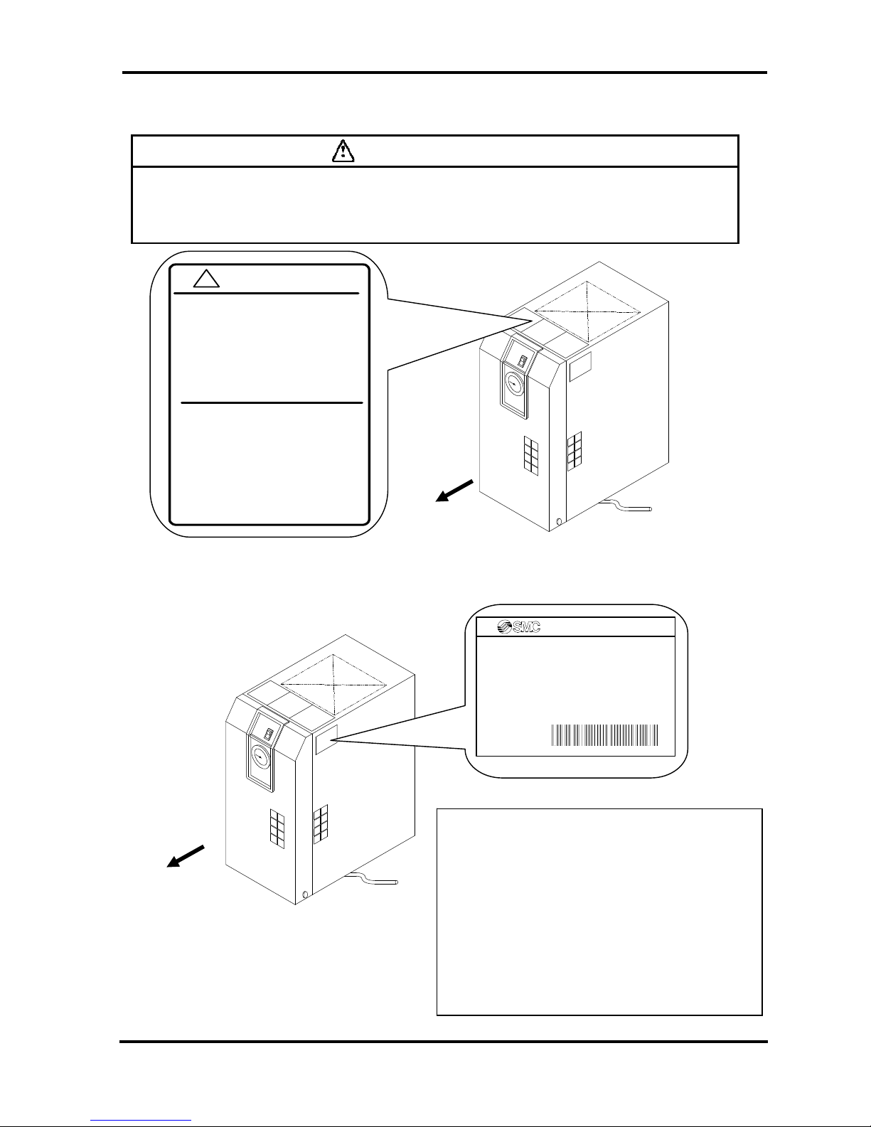
i – 2 – 8 Cautions about Usage
Warning
Read with caution and pay attention to the notations on danger warning labels.
Do not remove or rub danger warning labels.
Cimfirm the positions of danger warning labels.
i – 2 – 9 Other Label
Comfirm the model, contents of specifications on the label.
Front
S
p
ecification Label
Contents
MODEL: Model
VOL TAGE: Power supply voltage (frequency)
RUNNING CURRENT: Running current
REFRIGERANT: Type of refrigerant (amount)
WEIGHT:Weight MAX.PRESS: Maximum
operating pressure
SERIAL No.: Serial No.
MANUFACTURI NG DATE: Manufacturing Date
MADE IN: Country of manufacture
AIR DRYER
MODEL
VOLTAGE
RUNNING CURRENT
REFRIGERANT
WEIGHT MAX.PRESS.
SERIAL No.
MAKER
MADE IN
CAUTION 注意
!
1 Read man ual b efore operation.
2 Ensure van tilation and maintenance
space.
3 Keep water aw ay from the p r oduct.
4 Secur e In / O ut c onn ector w ith spa n ne r
during piping.
5 Wait 3 minutes before restart.
6 Ensure Running Condition / Evaporating
Temp . in g r een z one .
1 ご使用前に必ず取扱説明書を読んでください。
2 通風、メンテナンススペースを確保して
ください 。
3 雨や水滴がかからないようにしてください。
4 IN/OU Tポー トをスパ ナで 固定し て
配管 して くださ い。
5 再起動は運転停止3分後に行ってください。
6 RUNNING CONDITION・蒸発温度計は
グリーン帯で使用してください。
Front
i - 7
Page 11
Air Dryer(IDF1E-10~IDF15E-10/20) i Safety Instructions
i – 3 Disposal
When you dispose of the product, you shoud collect the refrigerant and the refrigerat oil enclosed in the ref ri ge r ant
circuit.
Caution
A sort of Fluorocarbon (HFC) is used for this product as refrigerant.
This product is specified by “Class1 Fluorocarbon Collection Destruction Law
in Japan.”
It is strictly forbitten by the law to emit the refrigerant to the atmosphere. Before
you repair this product, you should collect the refrigirant with “Refriger ant
collector.” Then, ask a destruction agenc y to dis pos e of collected refrigerant.
No one but someone have enough knowledge and experience about the product
and incidental devices should do the collection of the refrigerant.
No one but service person or qualified perso n shoud remove the cover panel of
the product.
The quantity and the sort of the Fluor ocarbon are printed on the specification
label.
Caution
Dispose of the refrigerant and refrigerant oil accordin g to the bylaw or regulation
of local government.
Do not dispose of refrigerant oil together with domestic garbage. And do not
burn it in unauthorized incinerators.
No one but someone have enough knowledge and experience about the product
and incidental devices should do the collection of the refrigerant oil.
No one but service person or qualified perso n shoud remove the cover panel of
the product.
If there are something not clear, please contact our service office.
i – 8
Page 12

Air Dryer(IDF1E-10~IDF15E-10/20) i Safety Instructions
i – 4 Limited warranty and Disclaimer / Compliance Requirements
The product used subject to the following “Limited warranty and Disclaimer“ and “Compliance Requirements.
Read and accept them before using the product.
Limited warranty and Disclaimer
1. The warranty period of the product is 1 year in service or 1.5 years after the produc t is delivered.
Also, the product may have specified durability , running distance or replacement parts. Please consult
your nearest sales branch.
2. For any failure or damage reported within the warranty period which is clearly our responsibility, a
replacement product or necessary parts will be provided.
This limited warranty applies only to our product independently, and not to any other da mage incurred
due to the failure of the product.
3. Prior to using SMC products, please read and understand the warranty terms and disclaimers noted in
the specified catalog for the particular products.
Compliance Requirements
1. The use of SMC products with production equipment for the manufacture of weapons of mass
destruction (WMD) or other weapon is strictly prohibited.
2. The exports of SMC products or technology from one country to another are govemed by the relevant
security laws and regulation of the countries involved in the transaction. Prior to the shipment of a SMC
product of a SMC product to another country, assure that all local rules goveming that export are known
and followed.
Caution
The Product is provided use in manufacturing industries.
The product herein described is bas ic ally provided for peaceful use in manufacturing industries.
If considering using the product in other industries, consult SMC beforehand and exchange
specifications or a contact if necessary.
If anything is unclear, contact your nearest sales branch.
i – 9
Page 13

Air Dryer (IDF1E-10~IDF15E-10/20) 1 Name and Functions Parts
1
Parts Name and Functions
1-1 Parts Name and Functions
y IDF1E ~ 3E
Front
Switch with Lamp
(ON/OFF Switch)
The lamp is continuously ON
during normal operation. Use it
for ON/OFF operations.
Evaporation thermometer
(EV APORATING TEMP)
Indicates the temperature of
refrigerant of low-pressure
side.
During normal driving, it
indicates in the green zone.
Top Ventilation Grille
(Outlet)
Hot air will be exhausted from
condenser by fan. No obstacles
shall be allowed to place on top
of it or even close the grille.
Inspection Grille
From this grille, confirm the
discharge of drain.
Panel Lock
Another one is on the left side.
No Front Panel
Drain Tube
Discharges drain.
It is covered with insulator, which
should not be removed.
Auto Drain
1 - 1
Page 14

Air Dryer (IDF1E-10~IDF15E-10/20) 1 Name and Functions Parts
y IDF1E ~ 3E-10 (100V AC specification)
Panel Lock
Another one is on the right side
Air outlet(OUT)
Port size:Rc3/8
Air inlet (IN)
Port size: Rc3/8
Rear Ventilation Grille (Inlet)
Breathe in cooling air from this
grille. Do not bung up with wall
and so on.
Earth Screw
Connect the earth to this screw
Power Cord
Insert the plug to a 100V AC only
outlet.
Front
y IDF3E-20 (200V AC specification)
Membrane Grommet
Power cord outlet
Front
Electrical Terminal Cover
(Width 6.5mm and below)
Applied Pressure Terminal: 1.25-3
Terminal Connecting Screw: M3
Customer Connection Side
Y ou ca n see the terminal block when
you remove this cover. Connect the
power cable through the membrane
grommet.
L
N
PE
( )
1 - 2
Page 15

Air Dryer (IDF1E-10~IDF15E-10/20) 1 Name and Functions Parts
y IDF4E ~ 15E
Front
Switch with Lamp
(ON/OFF Switch)
The lamp is continuously ON
during normal operation. Use
it for ON/OFF operations.
Evaporation
Thermometer
(EV APORATING TEMP)
Indicates the temperature of
refrigerant of low-pressure
side.
During normal driving, it
indicates in the green zone.
Right Side Ventilation
Grille (Outlet)
Waste heat will be exhausted
as hot air by the fan motor. Do
not block with wall and so on.
Inspection Grille
Confirm the discharge of drain
from this grille once a day.
Panel Lock
Another one is on the left side
Discharge drain.
Drain Tube
View with Front Panel removed
Do not remove the insulation on
the auto drain.
Auto Drain
1 - 3
Page 16

Air Dryer (IDF1E-10~IDF15E-10/20) 1 Name and Functions Parts
y IDF4E ~ 15E-10(100V AC specification)
y IDF4E ~ 15E-20 (200V AC specification)
Fixing Screw for Front Panel
Another one is on the right side.
Air Outlet (OUT)
Air Inlet (IN)
Left Side Ventilation
Grille (Inlet)
Breathe in cooling air
from this grill. Do not
bung up with wall and so
on.
Screw for the Earth
Connect the earth to this
screw
Power Cord
Insert the plug to an
outlet for exclusive use of
100V AC.
Front
Rear Panel
Y ou ca n see the terminal block when
you remove this cover. Connect the
power cable through the membrane
grommet.
Membrane Grommet
Power cord outlet
(Width 6.5mm and below)
Applied Pressure Terminal: 1.25-3
Terminal Connecting Screw: M3
Customer Connection Side
L
N
PE
( )
Front
1 - 4
Page 17

Air Dryer (IDF1E-10~IDF15E-10/20)
2 Transportation / Installation
Transportation / Installation
2
Warning
Use the product in the right way. During Installation, operation, maintenance, and check,
you should be careful in keeping the safety of human body.
Caution
Transportation, installation, and maintenance including dangerous work must be done by
a personnel who has enough knowledge and experience about the product and the
sysytem.
2-1
Transportation
When you transport the product, you should follow these instructions below.
• You should uplift the product from the base surface with careful attention to prevent falling sideways and drop.
• Do not bring the product lying sideways. If you lay it sideways, it will be broken.
• Do not hang up the product.
• Do not transport the product with any part such as an air filter mounted on the fittings at the air inlet or outlet port
of the product. If it is unavoidable to transport the product with such a part mounted, support the mounted part
with a bracket to prevent the product from being affected by vibration during transportation.
Warning
Those instructions above must be followed because the product is so heavy that it carries
a great risk to transport.
IDF4~11E are 20kg or more. They must be transported by more than one person, a forklift
and so on.
IDF15E is 46kg or more. They must be transported by forklift.
2 - 1
Page 18

Air Dryer (IDF1E-10~IDF15E-10/20)
2 Transportation / Installation
2-2 Installation
2-2-1 Location
The product should not be used or stored in the circumstances as follows. Those
circumstances will cause not only malfunction but also failures.
• Environment where the product is exposed to
rainwater, moisture vapor, salty water, oil and
so on.
• Locations where dust or particles are.
• Locations where inflammable or explosiv e gas
are.
• Locations where corrosive gas, solvent,
combustible gas are.
• Locations that receive direct sunlight or where
radiant heat is generated.
• Locations where ambient temperature is
beyond following range:
On-stream: 2 ~ 40
o
C
Storage: 0 ~ 50
o
C (when there is no drain
water inside of the piping)
• Locations where temperature changes rapidly.
• Locations where strong electromagnetic no ise
is generated (locations where electromagnetic
field, strong magnetic field, surge is generated)
• Circumstances where static electricity is
produced or discharged through the body of the
product.
• Locations where strong high frequency wave is
generated.
• Locations where danger of thunder is apparent.
• Locations by loading on vehicles, marine
vessels, and so on.
• Locations whose altitude is higher than 2,000
meters.
• Circumstances where strong vibration or impact
are transmitted.
• Circumstances where too much force and
weight are put on the body of the product that
causes it to deform.
• Circumstances where enough spaces cannot
be taken to do maintenance (in the plant where
the product is operated).
Spaces needed for maintenance
Front : 600 mm
Rear : 600 mm
Top : 600 mm
Right : 600 mm
Left : 600 mm
• Locations the ventilation grille of the product
can be blocked.
• Place where rejection style air of air
compressor or other driers (hot wind) is inhaled.
2-2-2 Anchorage
• The air dryer should be installed on a vibration-free, stable, horizontal flat surface.
• Refer to “Chapter6 6-2 Dimensions” for the dimensions.
• IDF4E~15E should be bolted by anchor bolts to prevent falling. We recommend the anchor bolt sets that
we are selling separately as accessories.
2-2-3 Air piping
• Connection to the inlet and outlet of compressed air should be made removable by using union and so on.
• Pressing the hexagonal fitting with screw wrench and so on, connect the air piping fittings to the body.
• When mounting any part such as an air filter on the fitting at the compressed air inlet or outlet port, support the
part to prevent excessive force from being applied to the product.
• Be careful not to let the vibration of the air compressor transmit.
• If the temperature of compressed air on the inlet side is higher than 50
o
C, place an aftercooler after the air
compressor. Or, make the temperature of the place where the air compressor is installed lower than 50
o
C.
2 - 2
Page 19

Air Dryer (IDF1E-10~IDF15E-10/20)
2 Transportation / Installation
• Flash the piping sufficiently in order to avoid any foreign substances such as dust, sealing tape, liquid gasket, etc.
when piping before piping connection.Foreign substances in the piping can caus e cooling failure or drainage
failure.
• Use pipes and fittings that have enough endurance against the operating pressure and temperature. And
connect it firmly to prevent air leakage.
• Provide bypass piping to make it possible to do maintenance without stopping the air compressor.
We recommend the bypass piping sets that
we are selling separately as accessories.
The bypass piping sets
2-2-4 Drain Tube
• A polyurethane tube of 10mm external diameter is attached to the drain tube. The outlet end of the tube is
released to atmosphere. And let drain flow through the tube into a scupper and so on.
• Using the pressure of the compressed air, drain will be discharged periodically. Fix the outlet end of the tube so
as not to swing during discharge.
• Prevent the drain tube from riser piping.
• Prevent the drain tube from being folded or flatted. Since the drain tube is coming from the bottom of the body,
be careful to avoid the body from stomping over the tube during installation.
Warning
During drain work, follow the procedure that you define to keep the safety of worker (ex. Put on
protective glass, apron, and gloves).
In case that oil gets mixed in the wasted water that is discharged from the auto drain, the waste liquid treatment
is necessary. Handle it following the bylaw or regulation of local government.
2 - 3
Page 20

Air Dryer (IDF1E-10~IDF15E-10/20)
2 Transportation / Installation
2 – 2 – 5 Electric Wiring
Warning
No one but qualified person should do the wiring work.
・ Before wiring, you must cut the power off for safety. Do not work under any
energized conditions.
・ Supply power from a stable place, which is free from the effect of surge.
・ Ensure that a Ground Fault Circuit Interrupter(GFCI) with appropriate capacity for
earth leakage and load is used in the power supply of the product to prevent
electrical shock and burnout of the compressor motor. See “6-1 List of
specifications” for details.
・ Supply power for the product should meet the specifications.
The product should be grounded for safety.
・ Do not connect the earth to a water pipe, a gas pipe, or a lightening rod.
・ Do not plug too many leads into a single socket. That causes exothermic heat or
fire.
・ Do not convert the wiring to use.
・ In European countries, a circuit breaker that meets the IEC standard should be used
for the supply power.
There are two methods depends on model (specified power).
IDIDF1E-10 ~ 15E-10 (100V specified)
• Insert the power plug into an outlet of 100V AC.
Install a Ground Fault Circuit Interrupter(GFCI) to the power supply (sensitivity of leak current
30mA and rated current 10A).
(Prepare by yourself)
• Do not extend the power cable using power strip and so on. That causes decrease of the voltage and the product
cannot be operated.
F3E-20 ~ 15E-20 (200Vspecified)
• Remove the terminal block cover or the rear cover in the rear of the product, and connect the power (200V AC)
to the terminal block.
•
Install a Ground Fault Circuit Interrupter(GFCI) to the power supply (sensitivity of leak current
30mA and rated current 10A).
(Prepare by yourself)
Specification of power cable
Prepare following power cable.
Power cable: 1.25mm
2
(16AWG), Three-cores (including the earth), External diameter: about 8 ~ 12mm
Additional length of about 0.1m is needed to wire inside of the product.
Length of the power cable
The length of the power cable should extend less than 30m from the product.
Connecting to the power supply
Connect the power cable and the earth to the terminal block. M3 screw is used for the connection part. Make sure
to use round crimped terminal.
Applicable crimped terminal: 1.25-3 (Width: 6.5mm and below)
Wiring procedure
• Remove the terminal block cover or the rear panel.
• Insert the cor d through the membrane grommet and connec t it to the terminal block (refer to the label on the
terminal block). M3 screw tightening torque: 0.6~1Nm
During wiring work, do not touch other sections except terminal block.
• Attach the cover or the rear panel as it were.
2 - 4
Page 21

Air Dryer (IDF1E-10~IDF15E-10/20)
2 Transportation / Installation
2-3
2 - 5
Page 22

Air Dryer (IDF1E-10~IDF15E-10/20)
2 Transportation / Installation
2 - 6
Cautions about Reinstallation
Caution
No one but someone who has enough knowledge about the product and
incidental devices should reinstall in another place. And following instructions
must be executed.
If you move the product and reinstall it into another place after some operations (including trial running),
instructions that are not only following ones but also all of those in the chapter 2 should be followed.
0BDisassembly of the power cable
Cut off the power source when you disassemble the power cable.
1BDisassembly of the air piping
• Remove the seal tape completely after detaching the piping. Remained tape will cause imperfect cooling
and failure by entering into the body of the product.
Residual compressed air pressure release procedure
• Even while the dryer is removed, only when compressed air is needed, open the bypass piping valve.
• Close the compressed air inlet and outlet valve.
• Unscrew the front panel fixing screw (in 2 points) and remove the front panel with upholding it a little.
• Open the residual pressure release cock of auto drain tube, and release compressed air pressure l eft inside o f
the product. Refer to the figure at right.
Warning
No one but qualified personnel should do the electric wiring.
Cut off the power supply for safety before the wiring. Do not work under energized
condition.
Warning
No one but qualified personnel should do the air piping.
Separate the compressor from the product for safety before removing the piping.
Do not remove any piping when there is remaining compressed air pressure inside
of it.
Case Assembly
The ramainder depressure cock.
※
It opens when turning in the
drection og the arrow of figure.
Page 23

Air Dryer (IDF1E-10~IDF15E-10/20) 3 Operation / Shutdown
3
Operation / Shutdown
Caution
No one but someone who has enough knowledge and experience about the product and
incidental devices should operate or shut down the product.
3-1 Check points before operation
Before a trial running, check following points.
• Installed Condition
By visual inspection check that the product is installed horizontally.
The product make sure the product is fixed enough with anchor bolts.
Do not place heavy obstacles on the product and add unreasonable loading by piping and so on.
• Wiring Connections
Power cord, and the earth should be connected firmly.
• Drain Tube
Drain tube should be connected correctly.
• Air Piping
Make sure the piping for compressed air is connected correctly. Those valves of IN / Out side of the product and
of the bypass piping should be completely fasten.
3-2 Operation
Start operation according to the procedure below.
• Turn on the breaker of the main power supply. Then, turn on the illuminated switch.
• The lamp will light u p. Few minutes later, the cooling fan will rotate and hot air will be exha usted from the
ventilation grille.
Place of the ventilation grille: IDF1E ~ 3E: Top Ventilation Grille
IDF4E ~ 15E: Right Side Ventilation Grille
• Open the IN / Out side valve slowly. Make sure the bypass valve is completely closed. Confirm there is no air
leakage.
• Depending on the condition of compressed air or ambient temperatur e, the cooli ng fan so metimes alt ernates
between rotation and stop at the beginning. Then, the refrigerator will go into continuous run and the pointer of
the evaporation thermometer will indicate in the green zone. If the pointer of the evaporation thermometer
indicates higher than the green zone, refer to “Chapter5 Troubleshooting.”
• After a while from the start of flowing the compressed air, drain will be discharged from the drain tube
automatically.
• Keep the condition of continuous run to use.
3 - 1
Page 24

Air Dryer (IDF1E-10~IDF15E-10/20) 3 Operation / Shutdown
Caution
Avoid frequent On/Off operation, which can cause troubles.
The auto drain used for the product has a structre that closes the valve with air pressure hig her
than 0.15MPa. Therefore, until the pressure increase, air will be emitted form the drain outlet at
the begining of opening the IN side valve. Keep in mind that sometime the pressure cannot
increase enough with air compressor that has low dischage flow rate.
3-3 Shutdown
• Turn off the illuminated switch.
• The lamp will go out and then, the operation will be stopped. Depending on the condition of operation, hot air
continues to be emitted from the ventilation grille by the cooling fan for a while after turning off the switch,
which is not an abnormality but a process for safety shutdown.
3-4 Cautions about restart
• One must wait for at least 3 minutes before restarting air dryer after it has been shut down. Failure to do this
may cause safety devices to trip due to over load.
3-5 Check points before restart
Check following points before you start operation. If any abnormalities occur, immediately stop the operation. Turn off the
illuminated switch of the product and then the breaker to the power supply.
• There is no leakage of compressed air.
• Compressed air pressure, temperature, flow rate, and ambient temperature meet the specifications.
• Drain is being discharged from the drain tube.
• The pointer of evaporation thermometer is indicating in the green zone.
• There are no abnormal sound, vibration, or smelling.
3-6 Precautions for long-term non-operation
• If the product will not be operated for more than 24 hours, for example at the weekend, turn off the ILS (switch
with lamp) or power supply, for energy saving and safety. It is also recommended to r elease the pressure
inside the compressed air piping and this air dryer.
3 - 2
Page 25

Air Dryer (IDF1E-10~IDF15E-10/20)
4 Maintenance
4
MAINTENANCE
4-1 Daily Inspection
Check following points during usual operations. If you find some problems, immediately stop the ope ration and
refer to “Chapter 5 Troubleshooting” as soon as possible.
• There is no air leakage
• The running lamp is lighting during operation
• Drain is being discharged from drain tube
• The pointer of the evaporation thermometer indicates in the green zone when it is running with
pressurized air supply.
• The pointer of the evaporated thermometer indicates about 3~10
o
C lower than that of ambient
temperature when the product is suspended with no pressurized air supply.
• There is no abnormal sound or vibration coming up from the product.
• There are no abnormal smell or smoke coming up from the product.
4-2 Periodical Maintenance
4-2-1 Cleaning of ventilation grille (suction grille)
Clean dust and other foreign particles from the ventilation area with vacuum cleaner or air blow nozzle once a
month.
Danger
During air blowing, put on protective glass and mask to prevent dusts from coming into throat or eyes.
4-2-2 Service parts
It is recommended to replace the following parts regularly. The interval shown in this operation manual
depend on the operating conditions (ambient temperature, installation environment, etc.), so that they
are for reference .
• Table 1. List of parts to be replaced regularly
Description Recommended replacement interval
Pressure switch One Million times.
Fan motor 20,000 hours
Magnetic Contactor, Magnetic Switch (Note) One Million times.
*Note)If it is mounted by option ”T” (With terminal block for power supply , run , alarm signal and remote
operation) or special order.
4-2-3 Cleaning of Auto Drain Strainer
Remove the dust deposited in the auto drain strainer every month. Use neutral detergent for cleaning. If they are
too dirty, replace them and shorten the period of maintenance from next time.
• Auto Drain Strainer order part number
Part No. Name Quantity Applicable Model
IDF-S0001
Auto Drain Strainer
1 IDF1E, IDF2E, IDF3E, IDF4E
IDF-S0002
Auto Drain Strainer
1 IDF6E, IDF8E, IDF11E,IDF15E
4 - 1
Page 26

Air Dryer (IDF1E-10~IDF15E-10/20)
4 Maintenance
・ Maintenance of the air dryer should only be carried out by someone with sufficient knowledge and
experience of air dryers and related equipment.
・ Before carrying out maintenance, the important warnings in this manual must be thoroughly read and
understood.
Warnin
g
・ When replacing or cleaning parts of the air drye r, be sure to remove the compressed air pressure inside
the air dryer to “0”. Never remove the case assembly when the air dryer is operated or air pressure
remains inside. It is extremely dangerous if compressed air pressure remains inside the air dryer, as
parts may come flying off at speed when loosened, or other u nexpected accidents.
・ This product has parts that become hot during operation and a po wer supply with high voltage applie d.
There is a risk of burns due to heat or electrification by high voltage. Even when operation is shut down
after switching off the air dryer’s illuminated light, there are also charging lines. When working on the
charged sections, be sure to switch off the earth leaka ge breaker installed before starting work.
・ As some parts of the air dryer will remain hot, there is a risk of burns due to residual heat after the
power is switched off. So do not carry out replacement work until the temperature of these parts has
fallen to 50℃ or less. Wait for about 10 to 15 minutes as a guide.
・ When carrying out maintenance work on the auto drain strainer and auto drain, there is a risk of
touching the drain fluid during work. Please follow the safety procedure for operators specified by
customer.(Example: carry out work wearing safety glasses, apron and gloves to prevent discharged
fluid from touching the human body.)
・ Use neutral detergent solution to clean parts such as the auto drain strainer and auto drain. Never
use solvent such as thinner.
・ When removing the outer casing panel or case assembly of the auto drain, wear gloves to prevent
injuries.
Danger
How to clean and replace the auto drain/strainer.
Please execute work through the following procedure when an auto drain and auto drain
strainer are washed and you exchange it .
・Turn off the illuminated ON/OFF switch.
・Disconnect the earth leakage breaker at the power supply or unplug the powe r plug from the socket.
・ Fully close the IN/OUT valves. Only open the bypass when comp ressed air is required during work.
・ Only the point that is necessary for work please remove a decoration panel.
4 - 2
Page 27

Air Dryer (IDF1E-10~IDF15E-10/20)
4 Maintenance
SO
Drain tube
Open
Drain t ube
rerease bush
Close
Lock button
Residual
pressure
rerease cock
【IDF1E~11E】
・ Open the residual pressure release cock at
the drain tube connection port to release air
and drain fluid left in the product.
(Leave the drain tube connected and hold it
with hand so that it does not get twisted.)
・ Because drain may be given by air
pressure left in a product like a careful.
・ Remove the drain tube.
Pull out the tube while pushing up the drain
tube release bush.
Pull it do wn
slowly.
Mark
Lock button
Turn to 45
゜
(right or left)
・ Hold the case assembly lightly and pull down
the lock button with thumb. Then, turn the
case assembly to the left (or right) to 45°to
align the marks.
・ Release your thumb from the lock button and
slowly pull down the case assembly
(vertically) to remove it.
・ Remove the auto drain strainer and clean it. T ake ca re
not to cut your hand with the sharp edges of the
strainer.
Drain separator
body
Auto drain
strainer
“O”ring
Case a ssembly
CAUTION
Check that air
pres sure is zero
befor e servicing.
・ Pour solution of neutral detergent into the case
assembly and shake it well to clean.
・ Check the case O-ring for damage such as scratches,
twisting or foreign particles attached to it. Then, a pply
grease thinly and fit it in the groove in the case
assembly.
・ Fit the auto drain strainer to the case assembly and fit
it into the drain separator body. Turn it untill the lock
button clicks.
・ Try to turn the case assembly lightly and check that it
does not turn. If it turns, start with fitting the case
assembly to the body again.
・ Close the residual pressure release cock and mount
the drain tube and front panel as they were.
・ When reapplying compressed air to the air dryer, first
open the valve on the inlet side slowly. Check for
compressed air leak and if everything is all right, open
the valve on the outlet side.
・ If the auto drain strainer or case assembly is
damaged or very dirty, replace it with a new one.
4 - 3
Page 28

Air Dryer (IDF1E-10~IDF15E-10/20)
4 Maintenance
【IDF15E】
Lock button
Mark
Drain tube
Open
Close
Residual pressure
release cock
Drain tube
release bush
Lock button
T o remove the case assembly , turn it to
45
°until the lock button and mark a
Then, pull it down slowly .
lign.
・ O
pen the residual pressure release cock at the drain
tube connection port to release air and drain fluid left
in the product.
(Leave the drain tube connected and hold it with hand
so that it does not get twisted.)
S
O
Auto drain strainer
"O"ring
Lock button
Case assembly
Residual pressure
release cock
Release bush
・ Remove the tube while pushing the release bush.
・ Hold the case assembly lightly and pull down the lock button
with thumb.Then, turn the case assembly to the left (or right)
to 45°to align the marks,Release your thumb from the lock
button and slowly pull down the case assembly (vertically)
to remove it.
・ Remove the auto drain strainer and clean it. Take care not
to cut your hand with the sharp edges of the strainer.
・ Pour solution of neutral detergent into the case assembly
and shake it well to clean.
・ Check the case O-ring for damage such as scratches,
twisting or foreign particles attached to it. Then, apply
grease thinly and fit it in the groove in the case assembly.
・ Fit the auto drain strainer to the case assembly and fit it into
the drain separator body. Turn it untill the lock button clicks.
Try to turn the case assembly lightly and check that it does
not turn. If it turns, start with fitting the case assembly to the
body again.
・ Close the residual pressure release cock and mount the
drain tube and front panel as they were.
・ If the auto drain strainer or case assembly is damaged or
very dirty, replace it with a new one.
4 - 4
Page 29

Air Dryer (IDF1E-10~IDF15E-10/20) 5 Troubleshooting
Troubleshooting
5
Should any problem occur, inspect the following table, and if the problem cannot be solved, shut off the power supply and
then contact one of our sales offices for further instructions.
Problem Probable Causes Remedy
Power cord or plug is in loosening state
or completely pulling out.
Perform proper connection on the power cord and plug. Air dryer does not
operate and running
lamp does not light on,
even switch is ON.
Circuit breaker is OFF .
Confirm whether the proper capacity of the circuit
breaker is used.
It is not possible to restart the air dryer within 3
minutes after shutdown. Wait for 3 minutes before
restarting.
Resume the operation after resetting the circuit
breaker to ON. If the circuit breaker still trips to OFF,
failure of electrical insulation may have occurred.
Remove the power supply and contact one of our
agents for further instructions.
Installation place is poorly
ventilated. Ambient temperature
is too high.
Improve the ventilation system to lower the ambient
temperature.
The ventilation grilles are
obstructed by wall or clogged
with dust.
Install the air dryer more than 40cm away from the
wall.
Clean the ventilation grilles once a month.
Temperature of the compressed
air is too high.
Improve the ventilation system around air
compressor or make ambient temperature around air
compressor low to lower the temperature of
discharge from compressor.
Reduce the temperature of the compressed air by
installing an additional after-cooler after air dryer.
Running lamp
extinguishes and
compressor stops
during operation but
resumes normal
operation
illuminating the
lamp after a
period of time.
Supply voltage is not in the
following range:
100VAC: 90V ~ 110V/90V ~
121V (50/60Hz)
200VAC: 180V ~ 220V/180V ~
242V (50/60Hz)
Set the voltage to a proper value by installing a
transformer or review the electrical wiring.
Installation place is poorly
ventilated. Ambient temperature
is too high.
Improve the ventilation system to lower the ambient
temperature.
The ventilation grilles are
obstructed by wall or clogged
with dust.
Install the air dryer more than 40cm away from the
wall.
Clean the ventilation grilles once a month.
Evaporation
thermometer indicates
higher than green zone.
Temperature of the compressed
air is too high.
Improve the ventilation system around air
compressor or make ambient temperature around air
compressor low to lower the temperature of
discharge from compressor.
Reduce the temperature of the compressed air by
installing an additional after-cooler after air dryer.
Bypass valve of air dryer is not
fully closed.
Close the valve completely.
Drain is not discharged from auto
drain properly.
Check if the drain pipe has been raisen up or bent.
Check auto drain.
Check auto drain strainer.
Moisture occurs
downstream of the
compressed air
lines.
Confluence of piping with another
unit without air dryer.
Install air dryer on the line that does not have it.
Separate two lines not to converge.
Large pressure drop IN / OUT valve on the air dryer
side is not fully opened.
Open IN/OUT valve thoroughly.
5 - 1
Page 30

Air Dryer (IDF1E-10~IDF15E-10/20) 6 References
References
6
6-1
Specifications
Model
Specification
IDF1E IDF2E IDF3E IDF4E IDF6E IDF8E IDF11E IDF15E
50Hz 0.1 0.2 0.32 0.52 0.75 1.22 1.65 2.8 Air Flow Rate
m
3
/min (ANR)(Note 1)
60Hz 0.12 0.235 0.37 0.57 0.82 1.32 1.82 3.1
Operating Pressure 0.7MPa
Inlet Air Temperature 35oC
Ambient Temperature 32oC
Rated Condition
Pressurized Dew Point 10oC
Working Fluid Compressed Air
Inlet Air Temperature 5 ~ 50oC
Inlet Air Pressure 0.15 ~ 1.0MPa
Operating
Range
Ambient Temperature 2 ~ 40oC(Relative Humidity of 85% or less)
100VAC(50/60Hz)
Single phase AC100/100 , 110V[Voltage fluctuations±10%]
Power source
200VAC(50/60Hz)
Single phase AC200/200 , 220V
[Voltage fluctuations±10%]
100VAC(50/60Hz) 1 8 / 1 6 1 8 / 1 6 1 8 / 1 6 1 9 / 1 8 1 9 / 1 8 2 2 / 2 2 2 8 / 2 6 2 7 / 2 6 Starting current
(Note 2) A
200VAC(50/60Hz) 8 / 8 7 / 8 9/ 8 11 / 1 0 2 1 / 2 0 23 / 2 2
100VAC(50/60Hz) 2. 4 / 2 . 5 2 . 4 / 2 . 5 2 . 4 / 2 . 5 2 . 4 / 2 . 5 2 . 4 / 2 . 5 3 . 0 / 3 . 1 5 . 7 / 5 . 7 4 . 3 / 4 . 6Operating urrent
(Note 2) A
200VAC(50/60Hz) 1 . 2 / 1 . 3 1 . 2 / 1 . 3 1 . 2 / 1 . 3 1 . 5 / 1 . 5 3 . 4 / 3 . 0 3 . 4 / 3 . 1
Power
consumption
(Note 2) W
100VAC,200VAC
(50/60Hz)
180/202 180/202 180/202 180/202 180/202 208/236 385/440 480/480
100VAC 10A
Electrical Specification
Circuit Breaker
(Note 3)
200VAC 5A
Condenser Plate fin tube type with forced air cooling
Refrigerant R134a (HFC) (GWP:1300)
Refrigerant Charge(AC100V/200V) g
70±5 115 ±5 150 ±5 180 ±5 200 ±5 250 ±5 260 ±5 350 ±10
Drain Connection Rc3/8 Rc1/2 Rc3/4 Rc1
Drain Connection 10mm
Coating Color
Panel: Urbanwhite 1
Base: Urbangray 2
Weight kg 16 17 18 22 23 27 28 46
Applicable Compressor(Standard) kW 0.75 1.5 2.2 3.7 5.5 7.5 11 15
Note1: The data for l/min (ANR) is referring to the conditions of 20°C, 1atm . pressure & relative humidity of
65%.
Note 2: The value is that of under specified condition.
Note 3: Install cicuit breaker that comes with sensivity of
≤30mA.
6 - 1
Page 31

Air Dryer (IDF1E-10~IDF15E-10/20) 6 References
6-2 External Dimentions
IDF1E / IDF2E / IDF3E
B
N
M
Q
C
Ventilation
Ventilation
Powercord(Length:1.9m)
[AC100Vspecification]
[AC200Vspecification]
AirOutlet
PortSize
AirInlet
PortSize
PowerSupplyEntry(φ17)
DraftAirInlet
TerminalBlock
OnlyIDF3E‑20
J
H
GF
DE
[AC200Vspecification]
Length:0.82m)
Evaporation
Switch
Thermometer
WithLamp
DrainTube
(O.D.10
P
KL
A
CheckWindow
Drain
CheckWindow
Drain
measure:mm
Model Port size A B C D E F G H J K L M N P Q
IDF1E
Rc3/8 69 101 270 32 21 330
IDF2E
Rc3/8 51 232 138 24 327
IDF3E
Rc3/8 473 67 304 33 73 31 36 154 21 330
226 410
413
125
240 15
--38150
IDF4E / IDF6E / IDF8E / IDF11E
MN
C
Q
B
4‑φ13
Draft
AirOutlet
CheckWindow
Drain
CheckWindow
Drain
Length:0.82m)
Ventilation
Evaporation
Thermometer
Switch
Ventilation
DrainTube
(O.D.10,
WithLamp
P
L K
A
[AC100V specification]
PowerCord(Length:1.9m)
Airinlrt
AirOutlet
PortSize
PortSize
[AC200V specification]
TerminalBlock
H
J
DE
GF
[AC200V specification]
PowerSupplyEntry(φ17)
Model Port size A B C D E F G H J K L M N P Q
IDF4E
Rc1/2 453 13
IDF6E
Rc3/4 455
IDF8E
Rc3/4
IDF11E Rc3/4
284
15
240 80
275
300
80 230 32 1531 42
283
355
270
485
498
568
6 - 2
Page 32

Air Dryer (IDF1E-10~IDF15E-10/20) 6 References
IDF15E
K
M
P
L
A
C
B
Q
FG
DNE
H
Evaporation
Thermometer
Ventilation
Ventilation
DrainTube
WithLamp
Switch
(O.D.10
Length:0.82m)
4‑φ13
AirOutlet
Draft
AirOutlet
AirInlet
AirOutlet
Draft
TerminalBlock
[AC200Vspecification]
PortSize
PortSize
PowerSupplyEntry(φ17)
[AC200Vspecification]
Powercord(Length:1.9m)
[AC100Vspecification]
J
measur
e
:mm
Model Port size
ABCDEFGH J K LMNPQ
IDF15E
Rc1 300 603 578 41 54 396 87 258 43 15 270 101 380 314 16
6-3 Electrical Circuit
y IDF1E〜3E
OLR
CM Compressor Motor
FM
Fan Motor
SYMBOL
DESCRIPTION
C01
Capacitor For Running Compressor Motor
ILS
Capacitor For Starting Compressor MotorC02
Capacitor For Running FAN Motor
C11
Terminal Block
TB
Pressure Switch
PRS
PTC
Overload Relay
PTC Starter
Switch with Lamp
PC
Power Supply Code
Resister
R
Starting Relay
RY
TM
Terminal Block
AC100/100,110V
(50/60Hz)
AC200/200,220V
(
50/60Hz
)
※1
※2
※1
※2
PC
L
N
※2
※1
TB
P
CM
FM
ILS
OLR
PRS
PTC
PE
y ID F4E〜8E
AC200/200,220V
(50/60Hz)
L
N
PE
※2
※
1
TB
C11 for 200V
ILS
※
1
※2
OLR
PRS
CM
PTC
AC100/100,110
V
(50/60Hz)
※1
※2
PC
P
CM
FM
6 - 3
Page 33

Air Dryer (IDF1E-10~IDF15E-10/20) 6 References
y IDF11E-10
ILS
OLR
PRS
PC
PTC
C01
A
C100/100,110
V
(50/60Hz)
P
CM
FM
y IDF11E-20
C11
AC200/200,220
V
ILS
OLR
PRS
TB
PTC
L
N
PE
P
CM
FM
・ IDF15E-10・IDF15E-20
CM
ILS
OLR
PR
S
C02
TB
P
FM
RY
C11
RY
CM
ILS
OLR
C01
PR
S
C02
PC
P
FM
RY
RY
R
TM
6 - 4
Page 34

Air Dryer (IDF1E-10~IDF15E-10/20) 6 References
6-4 Compressed Air and Refrigerant Circu it / Operation Principles
y IDF1E
Compressed Air Circuit
Humid hot air entering air dryer is cooled in
the cooler. At this time, the condensed
moisture is separated from the air by the
drain separator and automatically
discharged.The dried clean air is heated by
the reheater untill it gets about the same
temperature as that of ambient air. It is then
discharged from air dryer outlet.
Refrigerant Circuit
The Fluorocarbon charged in the
refrigerant circuit is compressed by the
compressor and cooled by the condenser
to become liquid. Then, going through the
capillary tube, it is decreased the pressure
to reach a low temperature. Passing
through the cooler part, it
draws heat from
compressed air and intensely boils. Finally
it is inhaled into the compressor again. The
capacity control valve opens to prevent
dew drops from freezing when
compressed air is cooled enough.
y IDF2E,IDF3E
Compressed Air Inlet
Coole
r
Capillary Tube
Pressure Switch
Fan Moto
r
Evaporation Thernarete
r
Condenso
r
Compressor
Capacity Control
Valve
Dorain Outlet
Dorain Separator
Compressed Air Outle t
y IDF4E,IDF6E,IDF8E,IDF11E,IDF15E
Compressed Air Inlet
Coole
r
Capillary Tube
Pressure Switch
Fan Motor
Evaporation Th ernareter
Condenso
r
Compressor
Capacity Control
Valve
Dorain Outlet
Dorain Separator
Compressed Air Outle
t
Reheter
Compressed Air Inlet
Capillar
y
Tub
e
Pressure Switch
Fan Moto
r
p
Thermorete
r
Condenso
r
Compressor
Capacity Control
Valve
Dorain Outlet
Dorain Separato
r
ompressed Air Outlet
Heat Exchange r
6 - 5
 Loading...